1998 DODGE RAM 1500 Ball joint replace
[x] Cancel search: Ball joint replacePage 54 of 2627

(8) Remove the hub/bearing from the steering
knuckle (Refer to 2 - SUSPENSION/FRONT/HUB /
BEARING - REMOVAL).
INSTALLATION
CAUTION: The ball joint stud tapers must be
CLEAN and DRY before installing the knuckle.
Clean the stud tapers with mineral spirits to remove
dirt and grease.
NOTE: When installing hub/bearing with ABS
brakes, position the speed sensor opening towards
the front of the vehicle.
(1) Install the hub/bearing to the steering knuckle
and tighten the bolts to 163 N´m (120 ft. lbs.)(LD) or
176 N´m (130 ft. lbs.)(HD 4X2) (Fig. 19).
(2) Install the knuckle onto the upper and lower
ball joints (Fig. 19).
(3) Install the upper and lower ball joint nuts.
Tighten the upper ball joint nut to 54 N´m (40 ft.
lbs.) (on 1500 series only an additional 90É turn is
required) and the lower ball joint nut to 52 N´m (38
ft. lbs.)(on 1500 series only an additional 90É turn is
required)(LD) or 135 N´m (100 ft. lbs.)(HD 4X2).
(4) Remove the hydraulic jack from the lower sus-
pension arm.
(5) Install the tie rod end and tighten the nut to
61 N´m (45 ft. lbs.).
(6) Install the front halfshaft into the hub/bearing
(if equipped).
(7) Install the the halfshaft nut and tighten to 251
N´m (185 ft. lbs.) (if equipped).(8) Install the ABS wheel speed sensor if equipped
(Refer to 5 - BRAKES/ELECTRICAL/FRONT
WHEEL SPEED SENSOR - INSTALLATION) and
brake shield, rotor and caliper (Refer to 5 - BRAKES/
HYDRAULIC/MECHANICAL/ROTORS - INSTALLA-
TION).
(9) Install the wheel and tire assembly (Refer to 22
- TIRES/WHEELS/WHEELS - STANDARD PROCE-
DURE).
(10) Remove the support and lower the vehicle.
(11) Perform a wheel alignment (Refer to 2 - SUS-
PENSION/WHEEL ALIGNMENT - STANDARD
PROCEDURE).
LOWER BALL JOINT
DIAGNOSIS AND TESTING - LOWER BALL
JOINT
NOTE: If the ball joint is equipped with a lubrication
fitting, grease the joint then road test the vehicle
before performing test.
(1) Raise the front of the vehicle. Place safety floor
stands under both lower control arms as far outboard
as possible. Lower the vehicle to allow the stands to
support some or all of the vehicle weight.
(2) Mount a dial indicator solidly to the topside of
the lower control arm and then zero the dial indica-
tor.
(3) Position the indicator plunger against the bot-
tom surface of the steering knuckle.
NOTE: The dial indicator plunger must be perpen-
dicular to the machined surface of the steering
knuckle.
(4) Position a pry bar under the tire assembly. Pry
upwards on the tire assembly.
(5) If the travel exceeds 0.5 mm (0.020 in.), replace
the lower ball joint (Refer to 2 - SUSPENSION/
FRONT/LOWER BALL JOINT - REMOVAL).
REMOVAL
(1) Remove the tire and wheel assembly.
(2) Remove the brake caliper and rotor (Refer to 5
- BRAKES/HYDRAULIC/MECHANICAL/ROTORS -
REMOVAL).
(3) Disconnect the tie rod from the steering
knuckle (Refer to 19 - STEERING/LINKAGE/TIE
ROD END - REMOVAL).
(4) Remove the steering knuckle (Fig. 20)(Refer to
2 - SUSPENSION/FRONT/KNUCKLE - REMOVAL).
(5) Move the halfshaft to the side and support the
halfshaft out of the way (If Equipped).
Fig. 19 STEERING KNUCKLE
1 - STEERING KNUCKLE
2 - LOWER CONTROL ARM
3 - LOWER BALL JOINT NUT
DRFRONT - INDEPENDENT FRONT SUSPENSION 2 - 19
KNUCKLE (Continued)
Page 55 of 2627

(6) Remove the snap ring, from the lower control
arm (HD 4X2 only)
NOTE: Extreme pressure lubrication must be used
on the threaded portions of the tool. This will
increase the longevity of the tool and insure proper
operation during the removal and installation pro-
cess.
(7) Press the ball joint from the lower control arm
using special tools C-4212±F (PRESS), 8698-2
(RECEIVER) and 8698-3 (DRIVER) (Fig. 21).
INSTALLATION
NOTE: Extreme pressure lubrication must be used
on the threaded portions of the tool. This will
increase the longevity of the tool and insure proper
operation during the removal and installation pro-
cess.
(1) Install the ball joint into the control arm and
press in using special tools C-4212±F (press), 8698-1
(driver) and 8698-3 (receiver) (Fig. 22).
(2) Install the ball joint boot.
(3) Stake the ball joint flange in four evenly
spaced places around the ball joint flange, using a
chisel and hammer (LD only).
(4) Replace the snap ring (HD 4X2 only)
(5) Remove the support for the halfshaft and
install into position (If Equipped).
(6) Install the steering knuckle (Refer to 2 - SUS-
PENSION/FRONT/KNUCKLE - INSTALLATION).
(7) Install the tie rod end into the steering knuckle
(Refer to 19 - STEERING/LINKAGE/TIE ROD END -
INSTALLATION).
(8) Install and tighten the halfshaft nut to 251
N´m (185 ft. lbs.). (If Equipped).
(9) Install the brake caliper and rotor (Refer to 5 -
BRAKES/HYDRAULIC/MECHANICAL/ROTORS -
INSTALLATION).
(10) Install the tire and wheel assembly (Refer to
22 - TIRES/WHEELS/WHEELS - STANDARD PRO-
CEDURE).
(11) Check the vehicle ride height (Refer to 2 -
SUSPENSION/WHEEL ALIGNMENT - STANDARD
PROCEDURE).
Fig. 20 LOWER BALL JOINT SEPARATION
1 - STEERING KNUCKLE
2 - SPECIAL TOOL 8677
Fig. 21 REMOVAL LOWER BALL JOINT
1 - PRESS - C-4212-F
2 - DRIVER - 8698-3
3 - BALL JOINT
4 - RECEIVER - 8698-2
Fig. 22 INSTALL LOWER BALL JOINT
1 - PRESS - C-4212-F
2 - DRIVER - 8698-1
3 - BALL JOINT
4 - LOWER CONTROL ARM
5 - RECEIVER - 8698-3
2 - 20 FRONT - INDEPENDENT FRONT SUSPENSIONDR
LOWER BALL JOINT (Continued)
Page 62 of 2627

INSTALLATION
CAUTION: The left and right side torsion bars are
NOT interchangeable. The bars are identified and
stamped R or L, for right or left. The bars do not
have a front or rear end and can be installed with
either end facing forward.
(1) Insert torsion bar ends into anchor and suspen-
sion arm.
(2) Position the anchor in the frame crossmember.
(3) Install Special Tool - 8686 to the anchor and
the crossmember (Fig. 30).
(4) Increase the tension on the anchor in order to
load the torsion bar.
(5) Install the adjustment bolt and the adjuster
nut.
(6) Turn adjustment bolt clockwise the recorded
amount of turns.
(7) Remove tool - 8686 from the torsion bar cross-
member (Fig. 30).
(8) Install the transfer case skid plate (Refer to 13
- FRAME & BUMPERS/FRAME/TRANSFER CASE
SKID PLATE - INSTALLATION).
(9) Lower vehicle and adjust the front suspension
height (Refer to 2 - SUSPENSION/WHEEL ALIGN-
MENT - STANDARD PROCEDURE).
(10) Perform a wheel alignment (Refer to 2 - SUS-
PENSION/WHEEL ALIGNMENT - STANDARD
PROCEDURE).
UPPER BALL JOINT
DIAGNOSIS AND TESTING - UPPER BALL
JOINT
NOTE: If the ball joint is equipped with a lubrication
fitting, grease the joint then road test the vehicle
before performing test.
(1) Raise the front of the vehicle. Place safety floor
stands under both lower control arms as far outboard
as possible. Lower the vehicle to allow the stands to
support some or all of the vehicle weight.
(2) Remove the front tires.(3) Mount a dial indicator solidly to the frame and
then zero the dial indicator.
(4) Position dial indicator plunger on the topside of
the upper ball joint (Fig. 32).
NOTE: The dial indicator plunger must be perpen-
dicular to the machined surface of the ball joint
(Fig. 32).
NOTE: Use care not to pry or tear the ball joint
boot, when checking the free play.
(5) Position a pry bar between the steering
knuckle and the upper control arm. Pry upwards on
the upper control arm (Fig. 32).
(6) If the travel exceeds 0.5 mm (0.020 in.), replace
the upper control arm since the upper ball joint is
integral to the arm (Refer to 2 - SUSPENSION/
FRONT/UPPER CONTROL ARM - REMOVAL).
(7) If the upper ball joint is within specs reinstall
the front tires (Refer to 22 - TIRES/WHEELS/
WHEELS - STANDARD PROCEDURE).
Fig. 32 UPPER BALL JOINT PLAY
1 - DIAL INDICATOR
2 - UPPER CONTROL ARM
3-PRYBAR
4 - KNUCKLE
5 - BALL JOINT BOOT
DRFRONT - INDEPENDENT FRONT SUSPENSION 2 - 27
TORSION BAR (Continued)
Page 69 of 2627

LOWER BALL JOINT
DIAGNOSIS AND TESTING - LOWER BALL
JOINT
To properly diagnose the lower ball joint two read-
ings from the dial indicator are necessary, The two
readings must be added together to find a total ball
joint movement as identified in the steps below.
(1) Raise and support the vehicle.
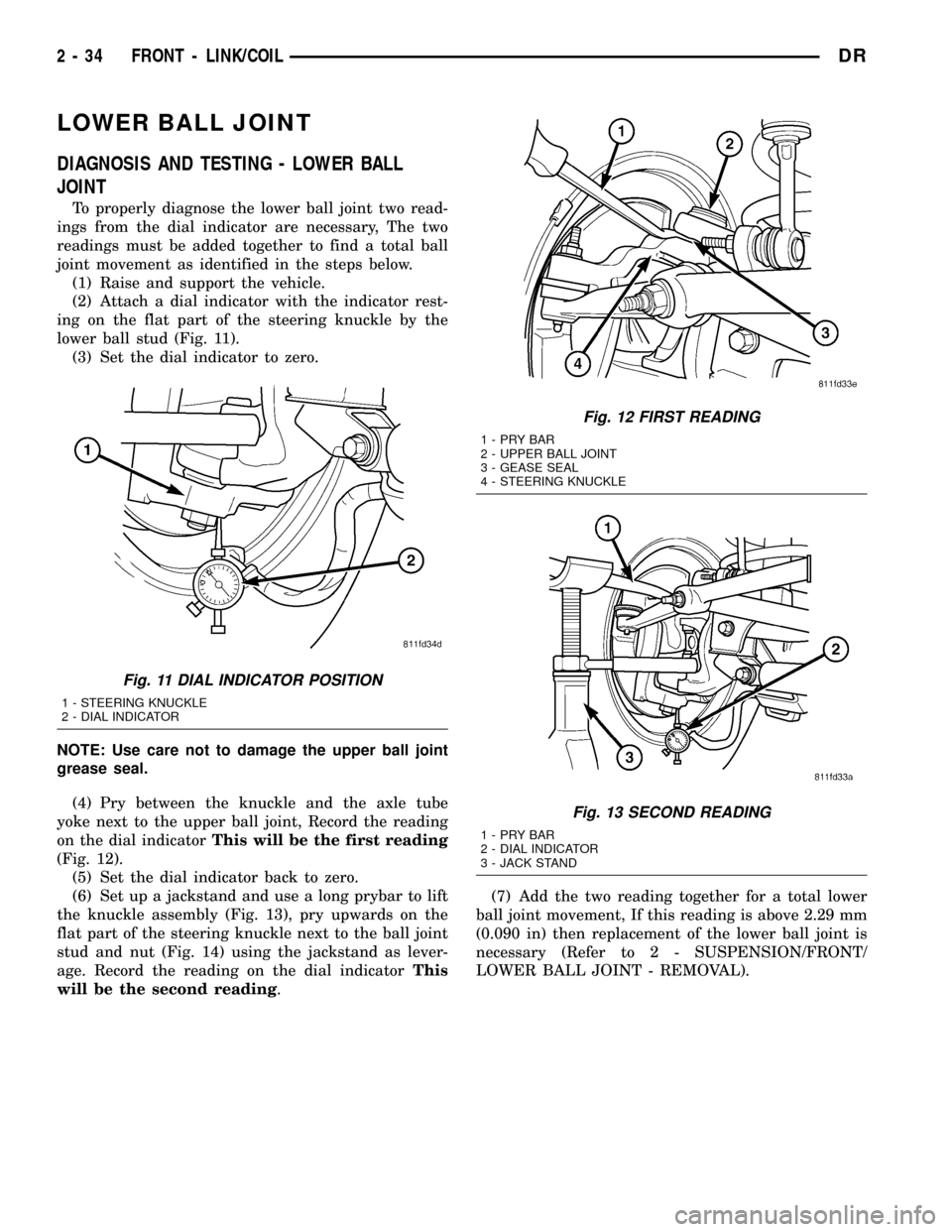
(2) Attach a dial indicator with the indicator rest-
ing on the flat part of the steering knuckle by the
lower ball stud (Fig. 11).
(3) Set the dial indicator to zero.
NOTE: Use care not to damage the upper ball joint
grease seal.
(4) Pry between the knuckle and the axle tube
yoke next to the upper ball joint, Record the reading
on the dial indicatorThis will be the first reading
(Fig. 12).
(5) Set the dial indicator back to zero.
(6) Set up a jackstand and use a long prybar to lift
the knuckle assembly (Fig. 13), pry upwards on the
flat part of the steering knuckle next to the ball joint
stud and nut (Fig. 14) using the jackstand as lever-
age. Record the reading on the dial indicatorThis
will be the second reading.(7) Add the two reading together for a total lower
ball joint movement, If this reading is above 2.29 mm
(0.090 in) then replacement of the lower ball joint is
necessary (Refer to 2 - SUSPENSION/FRONT/
LOWER BALL JOINT - REMOVAL).
Fig. 11 DIAL INDICATOR POSITION
1 - STEERING KNUCKLE
2 - DIAL INDICATOR
Fig. 12 FIRST READING
1-PRYBAR
2 - UPPER BALL JOINT
3 - GEASE SEAL
4 - STEERING KNUCKLE
Fig. 13 SECOND READING
1-PRYBAR
2 - DIAL INDICATOR
3 - JACK STAND
2 - 34 FRONT - LINK/COILDR
Page 71 of 2627

UPPER BALL JOINT
DIAGNOSIS AND TESTING - UPPER BALL
JOINT
To properly diagnose the upper ball joint two read-
ings from the dial indicator are necessary, The two
readings must be added together to find a total ball
joint movement as identified in the steps below.
(1) Raise and support the vehicle.
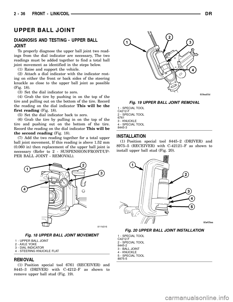
(2) Attach a dial indicator with the indicator rest-
ing on either the front or back sides of the steering
knuckle as close to the upper ball joint as possible
(Fig. 18).
(3) Set the dial indicator to zero.
(4) Grab the tire by pushing in on the top of the
tire and pulling out on the bottom of the tire. Record
the reading on the dial indicatorThis will be the
first reading(Fig. 18).
(5) Set the dial indicator back to zero.
(6) Grab the tire by pulling in on the top of the
tire and pushing out on the bottom of the tire.
Record the reading on the dial indicatorThis will be
the second reading(Fig. 18).
(7) Add the two reading together for a total upper
ball joint movement, If this reading is above 1.52 mm
(0.060 in) then replacement of the upper ball joint is
necessary (Refer to 2 - SUSPENSION/FRONT/UP-
PER BALL JOINT - REMOVAL).
REMOVAL
(1) Position special tool 6761 (RECEIVER) and
8445±3 (DRIVER) with C-4212±F as shown to
remove upper ball stud (Fig. 19).
INSTALLATION
(1) Position special tool 8445±2 (DRIVER) and
8975±5 (RECEIVER) with C-42121±F as shown to
install upper ball stud (Fig. 20).
Fig. 18 UPPER BALL JOINT MOVEMENT
1 - UPPER BALL JOINT
2 - AXLE YOKE
3 - DIAL INDICATOR
4 - STEERING KNUCKLE FLAT
Fig. 19 UPPER BALL JOINT REMOVAL
1 - SPECIAL TOOL
C4212-F
2 - SPECIAL TOOL
6761
3 - KNUCKLE
4 - SPECIAL TOOL
8445-3
Fig. 20 UPPER BALL JOINT INSTALLATION
1 - SPECIAL TOOL
C4212-F
2 - SPECIAL TOOL
8445-2
3 - BALL JOINT
4 - KNUCKLE
5 - SPECIAL TOOL
8975-5
2 - 36 FRONT - LINK/COILDR
Page 104 of 2627

(10) Remove ball (4) from the bearing cage (3) (Fig.
7).
(11) Repeat step above until all six balls are
removed from the bearing cage.
(12) Lift cage and inner race (2) upward and out
from the housing (1) (Fig. 8).
(13) Turn inner race 90É in the cage and rotate the
inner race/hub out of the cage (Fig. 9).INSTALLATION
NOTE: If C/V joint is worn, replace entire C/V joint
and boot.
(1) Clean all C/V joint components and shaft.
(2) Apply a light coat of grease supplied with the
joint/boot to the C/V joint components before assem-
bling them.
(3) Align the inner race, cage and housing accord-
ing to the alignment reference marks.
(4) Insert the inner race into the cage (Fig. 10) and
rotate race into the cage.
(5) Rotate the inner race/hub in the cage (Fig. 11).
(6) Insert cage into the housing (Fig. 12). Rotate
the cage 90É into the housing so the large bearing
hub counterbore is facing outwards.
Fig. 8 CAGE AND INNER RACE/HUB
1 - HOUSING
2 - INNER RACE
3 - CAGE WINDOW
Fig. 9 INNER RACE/HUB
Fig. 10 INNER RACE/HUB
1 - INNER RACE/HUB
2 - BEARING CAGE
Fig. 11 CAGE AND INNER RACE/HUB
1 - CAGE WINDOWS
2 - SNAP RING
DRHALF SHAFT 3 - 23
CV JOINT-OUTER (Continued)
Page 1516 of 2627

OIL COOLER & LINES
CLEANING
CLEANING AND INSPECTION
Clean the sealing surfaces.
Apply 483 kPa (70 psi) air pressure to the element
to check for leaks. If the element leaks, replace the
element.
OIL FILTER
REMOVAL
(1) Clean the area around the oil filter head.
Remove the filter from below using a cap-style filter
wrench.
(2) Clean the gasket surface of the filter head. The
filter canister O-Ring seal can stick on the filter
head. Make sure it is removed.
INSTALLATION
(1) Fill the oil filter element with clean oil before
installation. Use the same type oil that will be used
in the engine.
(2) Apply a light film of lubricating oil to the seal-
ing surface before installing the filter.
CAUTION: Mechanical over-tightening may distort
the threads or damage the filter element seal.
(3) Install the filter until it contacts the sealing
surface of the oil filter adapter. Tighten filter an
additional
1¤2turn.
OIL PAN
REMOVAL
(1) Disconnect the battery negative cables.
(2) Install engine support fixture # 8534.
(3) Raise vehicle on hoist.
(4) Disconnect starter cables from starter motor.
(5) Remove transmission and transfer case (if
equipped).
(6) Remove flywheel or flexplate.
(7) Remove starter motor (Refer to 8 - ELECTRI-
CAL/STARTING/STARTER MOTOR - REMOVAL)
and transmission adapter plate assembly.
WARNING: HOT OIL CAN CAUSE PERSONAL
INJURY.
(8) Drain the engine oil (Refer to 9 - ENGINE/LU-
BRICATION/OIL - STANDARD PROCEDURE).(9) Install the oil pan drain plug if sealing surface
is not damaged and tighten to 50 N´m (37 ft. lbs.)
torque.
(10) Remove oil pan bolts, break the pan to block
seal, and lower pan slightly and remove oil suction
tube fasteners.
(11) Remove oil pan and suction tube.
CLEANING
Remove all gasket material from the oil pan and
cylinder block sealing surfaces. Extra effort may be
required around T-joint areas. Clean oil pan and
flush suction tube with a suitable solvent.
INSPECTION
Inspect the oil pan, suction tube, and tube braces
for cracks and damage. Replace any defective compo-
nent. Inspect the oil drain plug and drain hole
threads. Inspect the oil pan sealing surface for
straightness. Repair any minor imperfections with a
ball-peen hammer. Do not attempt to repair an oil
pan by welding.
INSTALLATION
(1) Fill the T-joint between the pan rail/gear hous-
ing and pan rail/rear seal retainer with sealant. Use
MopartSilicone Rubber Adhesive Sealant or equiva-
lent.
(2) Place suction tube in oil pan and guide them
into place. Using a new tube to block gasket, install
and tighten the suction tube bolts by hand. Starting
with the oil pump inlet bolts, tighten the bolts to 24
N´m (18 ft. lbs.) torque. Tighten the remaining tube
brace bolts to 43 N´m (32 ft. lbs.) torque.
(3) Starting in the center and working outward,
tighten the oil pan bolts to 28 N´m (21 ft. lbs.)
torque.
(4) Install the flywheel housing assembly with the
starter motor attached and tighten bolts to 77 N´m
(57 ft. lbs.) torque.
(5) Connect starter motor cables.
(6) Install the flywheel or flexplate. Torque to 137
N´m (101 ft. lbs.).
(7) Install transmission and transfer case (if
equipped).
(8) Lower vehicle.
(9) Remove the engine support fixture # 8534.
(10) Install battery negative cables.
(11) Fill the crankcase with new engine oil.
(12) Start engine and check for leaks. Stop engine,
check oil level, and adjust, if necessary.
DRENGINE 5.9L DIESEL 9 - 293
Page 1658 of 2627

BINDING AND STICKING
CONDITION POSSIBLE CAUSE CORRECTION
DIFFICULT TO TURN WHEEL
STICKS OR BINDS1. Low fluid level. 1. Fill to proper level.
2. Tire pressure. 2. Adjust tire pressure.
3. Steering components (ball
joints/tie rod ends).3 Inspect and repair as necessary.
4. Loose belt. 4. Adjust or replace.
5. Low pump pressure. 5. Pressure test and replace if
necessary.
6. Column shaft coupler binding. 6. Replace coupler.
7. Steering gear worn. 7. Replace gear.
8. Pump seized / Stuck valve 8. Replace pump.
INSUFFICIENT ASST. OR POOR RETURN TO CENTER
CONDITION POSSIBLE CAUSE CORRECTION
HARD TURNING OR MOMENTARY
INCREASE IN TURNING EFFORT1. Tire pressure. 1. Adjust tire pressure.
2. Low fluid level. 2. Fill to proper level.
3. Loose belt. 3. Adjust or replace.
4. Low pump pressure. 4. Pressure test and repair as
necessary.
5. Internal gear leak. 5. Replace gear.
STEERING WHEEL DOES NOT
WANT TO RETURN TO CENTER
POSITION1. Tire pressure. 1. Adjust tire pressure.
2. Wheel alignment. 2. Align front end.
3. Lack of lubrication. 3. Inspect and lubricate suspension
compnents.
4. High friction in steering gear. 4. Replace gear.
LOOSE STEERING AND VEHICLE LEAD
CONDITION POSSIBLE CAUSE CORRECTION
EXCESSIVE PLAY IN STEERING
WHEEL1. Worn or loose suspension or
steering components.1. Inspect and repair as necessary.
2. Worn or loose wheel bearings. 2. Inspect and repair or adjust
bearings.
3. Steering gear mounting. 3. Tighten gear mounting bolts to
specification.
4. Gear out of adjustment. 4. Replace gear.
5. Worn or loose steering coupler. 5. Inspect and replace as
necessary.
VEHICLE PULLS OR LEADS TO
ONE SIDE.1. Tire Pressure. 1. Adjust tire pressure.
2. Radial tire lead. 2. Rotate tires.
3. Brakes dragging. 3. Repair as necessary.
4. Wheel alignment. 4. Align front end.
DRSTEERING 19 - 3
STEERING (Continued)