1998 DODGE RAM 1500 Drive belt removal
[x] Cancel search: Drive belt removalPage 1517 of 2627
OIL PRESSURE RELIEF VALVE
REMOVAL
(1) Disconnect the battery negative cables.
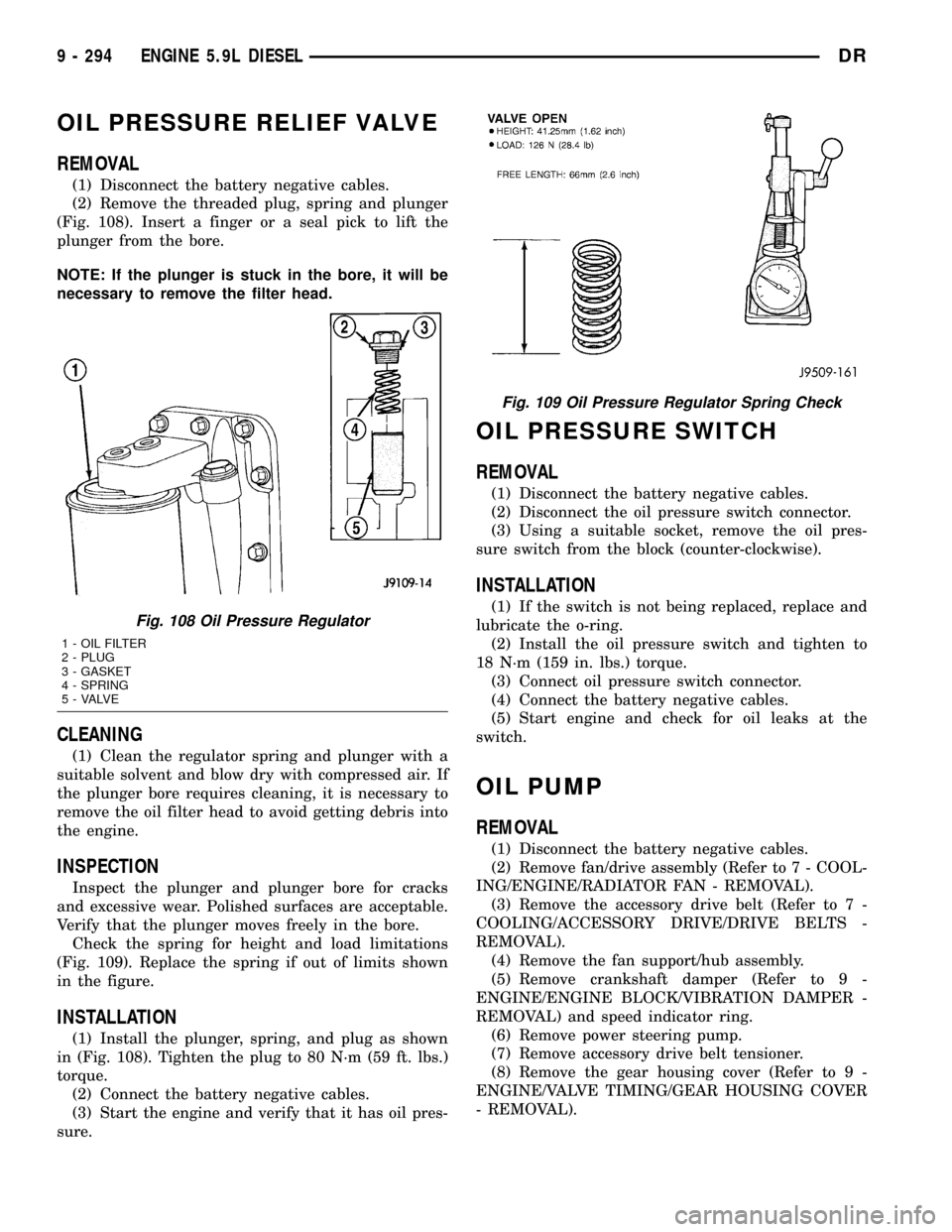
(2) Remove the threaded plug, spring and plunger
(Fig. 108). Insert a finger or a seal pick to lift the
plunger from the bore.
NOTE: If the plunger is stuck in the bore, it will be
necessary to remove the filter head.
CLEANING
(1) Clean the regulator spring and plunger with a
suitable solvent and blow dry with compressed air. If
the plunger bore requires cleaning, it is necessary to
remove the oil filter head to avoid getting debris into
the engine.
INSPECTION
Inspect the plunger and plunger bore for cracks
and excessive wear. Polished surfaces are acceptable.
Verify that the plunger moves freely in the bore.
Check the spring for height and load limitations
(Fig. 109). Replace the spring if out of limits shown
in the figure.
INSTALLATION
(1) Install the plunger, spring, and plug as shown
in (Fig. 108). Tighten the plug to 80 N´m (59 ft. lbs.)
torque.
(2) Connect the battery negative cables.
(3) Start the engine and verify that it has oil pres-
sure.
OIL PRESSURE SWITCH
REMOVAL
(1) Disconnect the battery negative cables.
(2) Disconnect the oil pressure switch connector.
(3) Using a suitable socket, remove the oil pres-
sure switch from the block (counter-clockwise).
INSTALLATION
(1) If the switch is not being replaced, replace and
lubricate the o-ring.
(2) Install the oil pressure switch and tighten to
18 N´m (159 in. lbs.) torque.
(3) Connect oil pressure switch connector.
(4) Connect the battery negative cables.
(5) Start engine and check for oil leaks at the
switch.
OIL PUMP
REMOVAL
(1) Disconnect the battery negative cables.
(2) Remove fan/drive assembly (Refer to 7 - COOL-
ING/ENGINE/RADIATOR FAN - REMOVAL).
(3) Remove the accessory drive belt (Refer to 7 -
COOLING/ACCESSORY DRIVE/DRIVE BELTS -
REMOVAL).
(4) Remove the fan support/hub assembly.
(5) Remove crankshaft damper (Refer to 9 -
ENGINE/ENGINE BLOCK/VIBRATION DAMPER -
REMOVAL) and speed indicator ring.
(6) Remove power steering pump.
(7) Remove accessory drive belt tensioner.
(8) Remove the gear housing cover (Refer to 9 -
ENGINE/VALVE TIMING/GEAR HOUSING COVER
- REMOVAL).
Fig. 108 Oil Pressure Regulator
1 - OIL FILTER
2 - PLUG
3 - GASKET
4 - SPRING
5 - VALVE
Fig. 109 Oil Pressure Regulator Spring Check
9 - 294 ENGINE 5.9L DIESELDR
Page 1522 of 2627
(3) Install heat shield and torque nuts to 15 Nm
(11 ft. lbs.).
(4) Install cab heater tube.
(5) Install exhaust manifold bolt retention straps.
(6) Install the cab heater return hose to the man-
ifold bolt stud. Tighten the nut to 24 N´m (18 ft. lbs.)
torque.
(7) Install the turbocharger and a new gasket.
Apply anti-seize to the studs and then tighten the
turbocharger mounting nuts to 43 N´m (32 ft. lbs.)
torque.
(8)Pre-lube the turbocharger.Pour 50 to 60 cc
(2 to 3 oz.) clean engine oil in the oil supply line fit-
ting on the turbo. Rotate the turbocharger impeller
by hand to distrubute the oil thoroughly.
(9) Install and tighten the oil supply line fitting
nut to 24 N´m (18 ft. lbs.) torque.
(10) Position the charge air cooler inlet pipe to the
turbocharger. With the clamp in position, tighten the
clamp nut to 11 N´m (100 in. lbs.) torque.
(11) Position the air inlet hose to the turbocharger.
Tighten the clamp to 11 N´m (100 in. lbs.) torque.
(12) Raise vehicle on hoist.
(13) Install the oil drain tube and a new gasket to
the turbocharger. Tighten the drain tube bolts to 24
N´m (18 ft. lbs.) torque.
(14) Connect the exhaust pipe to the turbocharger
and tighten the bolts to 11 N´m (100 ft. lbs.) torque.
(15) Lower the vehicle.
(16) Connect the battery negative cables.
(17) Start the engine to check for leaks.
VALVE TIMING
STANDARD PROCEDURE - TIMING
VERIFICATION
(1) Remove the cylinder head cover(Refer to 9 -
ENGINE/CYLINDER HEAD/CYLINDER HEAD
COVER(S) - REMOVAL).
(2) Remove fuel injector from cylinder number
1(Refer to 14 - FUEL SYSTEM/FUEL INJECTION/
FUEL INJECTOR - REMOVAL).
(3) Using Special Tool 7471B rotate the engine
until the TDC mark on the damper is at 12 o'clock.
(4) Using a 8 in.x 1/4 in. dowel rod inserted into
cylinder number 1, rock the crankshaft back and
forth to verify piston number 1 is at TDC.
(5) With cylinder number still at TDC, inspect the
keyway on the crankshaft gear for proper alignment
(12 o'clock position).
(6) If the keyway is not at 12 o'clock position
replace the crankshaft gear assembly.
(7) If the keyway is at 12 o'clock position, remove
front gear cover and verify timing mark alignmentbetween the camshaft gear and crankshaft gear, if
not aligned inspect keyway on camshaft gear.
(8) Inspect keyway on camshaft gear for proper
alignment with the key in the camshaft, if alignment
is off replace the camshaft/gear assembly.
(9) If timing marks alignment is off and no dam-
age is found at either the crankshaft or camshaft
gear keyways, realign timing marks as necessary.
GEAR HOUSING
REMOVAL
(1) Disconnect the battery negative cables.
(2) Raise vehicle on hoist.
(3) Partially drain engine coolant into container
suitable for re-use (Refer to 7 - COOLING - STAN-
DARD PROCEDURE).
(4) Lower vehicle.
(5) Remove radiator upper hose.
(6) Disconnect coolant recovery bottle hose from
radiator filler neck and lift bottle off of fan shroud.
(7) Disconnect windshield washer pump supply
hose and electrical connections and lift washer bottle
off of fan shroud.
(8) Remove lower fan shroud fasteners. Disconnect
fan drive wire harness.
(9) Remove the upper fan shroud-to-radiator
mounting bolts.
(10) Remove viscous fan/drive assembly (Refer to 7
- COOLING/ENGINE/RADIATOR FAN - REMOVAL).
(11) Remove the accessory drive belt (Refer to 7 -
COOLING/ACCESSORY DRIVE/DRIVE BELTS -
REMOVAL).
(12) Remove the cooling fan support/hub from the
front of the engine.
(13) Raise the vehicle on hoist.
(14) Remove the crankshaft damper (Refer to 9 -
ENGINE/ENGINE BLOCK/VIBRATION DAMPER -
REMOVAL) and speed indicator ring.
(15) Lower the vehicle.
(16) Remove the power steering pump.
(17) Remove the accessory drive belt tensioner.
(18) Remove the gear cover-to-housing bolts and
gently pry the cover away from the housing, taking
care not to mar the gasket surfaces.
(19) Remove the fuel injection pump (Refer to 14 -
FUEL SYSTEM/FUEL DELIVERY/FUEL INJEC-
TION PUMP - REMOVAL).
(20) Disconnect the camshaft position sensor con-
nector.
(21) Disconnect and remove engine speed sensor.
(22) Remove the camshaft (Refer to 9 - ENGINE/
ENGINE BLOCK/CAMSHAFT & BEARINGS (IN
BLOCK) - REMOVAL).
(23) Remove the six front oil pan fasteners.
DRENGINE 5.9L DIESEL 9 - 299
EXHAUST MANIFOLD (Continued)
Page 1524 of 2627
(23) Install the windshield washer reservoir to the
fan shroud and connect the washer pump supply
hose and electrical connection.
(24) Install the coolant recovery bottle to the fan
shroud and connect the hose to the radiator filler
neck.
(25) Install the radiator upper hose and clamps.
(26) Add engine oil.
(27) Add coolant (Refer to 7 - COOLING - STAN-
DARD PROCEDURE).
(28) Connect the battery cables.
(29) Start engine and inspect for leaks.
GEAR HOUSING COVER
REMOVAL
(1) Disconnect both battery negative cables.
(2) Raise vehicle on hoist.
(3) Partially drain engine coolant into container
suitable for re-use (Refer to 7 - COOLING - STAN-
DARD PROCEDURE).
(4) Lower vehicle.
(5) Remove radiator upper hose.
(6) Disconnect coolant recovery bottle hose from
radiator filler neck and lift bottle off of fan shroud.
(7) Disconnect windshield washer pump supply
hose and electrical connections and lift washer bottle
off of fan shroud.
(8) Remove viscous fan/drive assembly (Refer to 7 -
COOLING/ENGINE/RADIATOR FAN - REMOVAL).
(9) Remove the accessory drive belt (Refer to 7 -
COOLING/ACCESSORY DRIVE/DRIVE BELTS -
REMOVAL).
(10) Remove the cooling fan support/hub from the
front of the engine.
(11) Raise the vehicle on hoist.
(12) Remove power steering pump.
(13) Remove accessory drive belt tensioner.
(14) Remove the crankshaft damper and speed
indicator ring (Refer to 9 - ENGINE/ENGINE
BLOCK/VIBRATION DAMPER - REMOVAL).
(15) Lower the vehicle.
(16) Remove the gear cover-to-housing bolts and
gently pry the cover away from the housing, taking
care not to mar the gasket surfaces.
INSTALLATION
(1) Install a new front crankshaft oil seal.
(2) Obtain a seal pilot/installation tool from a
crankshaft front seal service kit and install the pilot
into the seal.
(3) Apply a bead of MopartSilicone Rubber Adhe-
sive Sealant or equivalent to the gear housing cover.
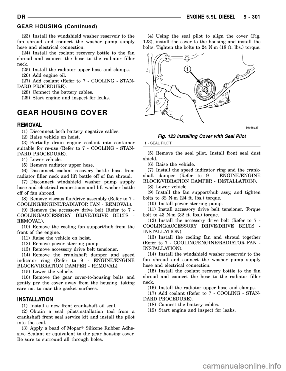
Be sure to surround all through holes.(4) Using the seal pilot to align the cover (Fig.
123), install the cover to the housing and install the
bolts. Tighten the bolts to 24 N´m (18 ft. lbs.) torque.
(5) Remove the seal pilot. Install front seal dust
shield.
(6) Raise the vehicle.
(7) Install the speed indicator ring and the crank-
shaft damper (Refer to 9 - ENGINE/ENGINE
BLOCK/VIBRATION DAMPER - INSTALLATION).
(8) Lower vehicle.
(9) Install the fan support/hub assy, and tighten
bolts to 32 N´m (24 ft. lbs.) torque.
(10) Install power steering pump.
(11) Install accessory drive belt tensioner. Torque
bolt to 43 N´m (32 ft. lbs.) torque.
(12) Install the accessory drive belt (Refer to 7 -
COOLING/ACCESSORY DRIVE/DRIVE BELTS -
INSTALLATION).
(13) Install the cooling fan and shroud together
(Refer to 7 - COOLING/ENGINE/RADIATOR FAN -
INSTALLATION).
(14) Install the windshield washer reservoir to the
fan shroud and connect the washer pump supply
hose and electrical connection.
(15) Install the coolant recovery bottle to the fan
shroud and connect the hose to the radiator filler
neck.
(16) Install the radiator upper hose and clamps.
(17) Add coolant (Refer to 7 - COOLING - STAN-
DARD PROCEDURE).
(18) Connect the battery cables.
(19) Start engine and inspect for leaks.
Fig. 123 Installing Cover with Seal Pilot
1 - SEAL PILOT
DRENGINE 5.9L DIESEL 9 - 301
GEAR HOUSING (Continued)
Page 1623 of 2627

REMOVAL
CAUTION: Cleanliness cannot be overemphasized
when handling or replacing diesel fuel system com-
ponents. This especially includes the fuel injectors,
high-pressure fuel lines and fuel injection pump.
Very tight tolerances are used with these parts. Dirt
contamination could cause rapid part wear and pos-
sible plugging of fuel injector nozzle tip holes. This
in turn could lead to possible engine misfire.
Always wash/clean any fuel system component
thoroughly before disassembly and then air dry.
Cap or cover any open part after disassembly.
Before assembly, examine each part for dirt, grease
or other contaminants and clean if necessary. When
installing new parts, lubricate them with clean
engine oil or clean diesel fuel only.
(1) Disconnect both negative battery cables at both
batteries. Cover and isolate ends of both cables.
(2) Remove intake manifold air intake tube (above
injection pump) and its rubber connector hose (Fig.
7).
(3) Remove accessory drive belt.
(4) Thoroughly clean the rear of injection pump,
and attachment points for its 3 fuel lines (Fig. 8).
Also clean the opposite ends of these same 3 lines at
their attachment points.
(5) Disconnect Fuel Control Actuator (FCA) electri-
cal connector at rear of injection pump (Fig. 9).
CAUTION: Whenever a fuel line fitting is connected
to a secondary fitting, always use a back-up wrench
on the secondary fitting. Do not allow the second-
ary fitting to rotate.
(6) Remove fuel line (injection pump-to-fuel pres-
sure limiting valve).
(7) Remove fuel line (injection pump-to-fuel rail).
Use back-up wrench on fitting at fuel pump.
(8) Remove fuel line (injection pump-to-fuel filter
housing).
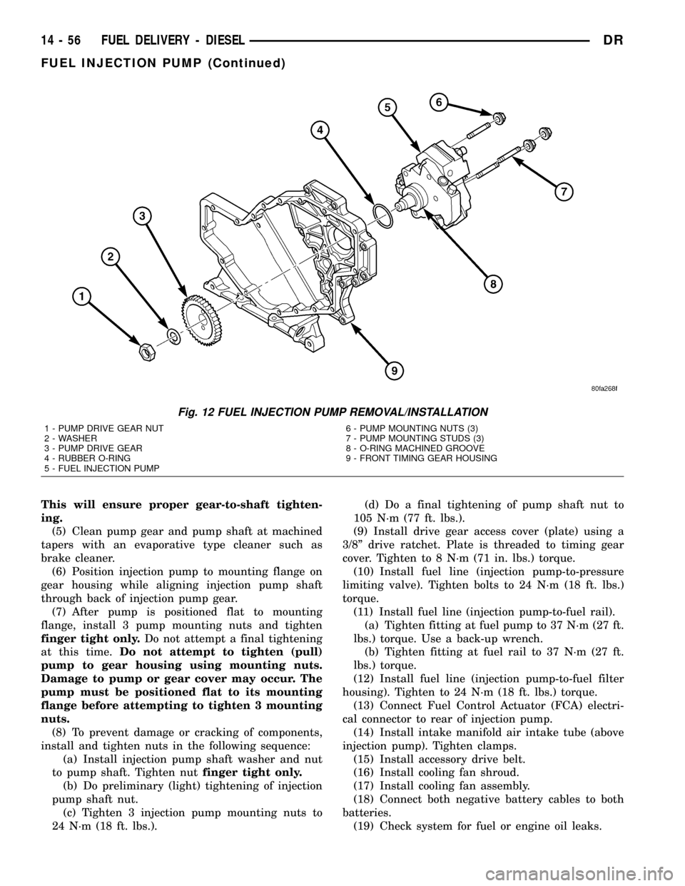
(9) Remove fuel pump drive gear access cover
(plate) with a 3/8º drive ratchet. Plate is threaded to
timing gear cover (Fig. 10).
(10) Remove fuel pump drive gear mounting nut
and washer.
(11) Attach C3428B, or L4407A (or equivalent)
gear puller (Fig. 11) to pump drive gear with 2 bolts,
and separate gear from pump (a keyway is not used
on this particular injection pump). Leave drive gear
hanging loose within timing gear cover.
(12) Remove 3 injection pump mounting nuts (Fig.
12), and remove pump from engine.
Fig. 7 INTAKE TUBE AND CONNECTING HOSE
1 - MANIFOLD ABOVE HEATERS
2 - RUBBER CONNECTING HOSE
3 - METAL INTAKE TUBE
4 - CLAMPS (2)
Fig. 8 OVERFLOW VALVE
1 - BANJO BOLTS
2 - PUMP MOUNTING NUTS (3)
3 - FUEL INJECTION PUMP
4 - CASCADE OVERFLOW VALVE
14 - 54 FUEL DELIVERY - DIESELDR
FUEL INJECTION PUMP (Continued)
Page 1625 of 2627
This will ensure proper gear-to-shaft tighten-
ing.
(5) Clean pump gear and pump shaft at machined
tapers with an evaporative type cleaner such as
brake cleaner.
(6) Position injection pump to mounting flange on
gear housing while aligning injection pump shaft
through back of injection pump gear.
(7) After pump is positioned flat to mounting
flange, install 3 pump mounting nuts and tighten
finger tight only.Do not attempt a final tightening
at this time.Do not attempt to tighten (pull)
pump to gear housing using mounting nuts.
Damage to pump or gear cover may occur. The
pump must be positioned flat to its mounting
flange before attempting to tighten 3 mounting
nuts.
(8) To prevent damage or cracking of components,
install and tighten nuts in the following sequence:
(a) Install injection pump shaft washer and nut
to pump shaft. Tighten nutfinger tight only.
(b) Do preliminary (light) tightening of injection
pump shaft nut.
(c) Tighten 3 injection pump mounting nuts to
24 N´m (18 ft. lbs.).(d) Do a final tightening of pump shaft nut to
105 N´m (77 ft. lbs.).
(9) Install drive gear access cover (plate) using a
3/8º drive ratchet. Plate is threaded to timing gear
cover. Tighten to 8 N´m (71 in. lbs.) torque.
(10) Install fuel line (injection pump-to-pressure
limiting valve). Tighten bolts to 24 N´m (18 ft. lbs.)
torque.
(11) Install fuel line (injection pump-to-fuel rail).
(a) Tighten fitting at fuel pump to 37 N´m (27 ft.
lbs.) torque. Use a back-up wrench.
(b) Tighten fitting at fuel rail to 37 N´m (27 ft.
lbs.) torque.
(12) Install fuel line (injection pump-to-fuel filter
housing). Tighten to 24 N´m (18 ft. lbs.) torque.
(13) Connect Fuel Control Actuator (FCA) electri-
cal connector to rear of injection pump.
(14) Install intake manifold air intake tube (above
injection pump). Tighten clamps.
(15) Install accessory drive belt.
(16) Install cooling fan shroud.
(17) Install cooling fan assembly.
(18) Connect both negative battery cables to both
batteries.
(19) Check system for fuel or engine oil leaks.
Fig. 12 FUEL INJECTION PUMP REMOVAL/INSTALLATION
1 - PUMP DRIVE GEAR NUT
2 - WASHER
3 - PUMP DRIVE GEAR
4 - RUBBER O-RING
5 - FUEL INJECTION PUMP6 - PUMP MOUNTING NUTS (3)
7 - PUMP MOUNTING STUDS (3)
8 - O-RING MACHINED GROOVE
9 - FRONT TIMING GEAR HOUSING
14 - 56 FUEL DELIVERY - DIESELDR
FUEL INJECTION PUMP (Continued)
Page 1694 of 2627
PUMP
TABLE OF CONTENTS
page page
PUMP
DESCRIPTION.........................39
OPERATION...........................40
DIAGNOSIS AND TESTING - PUMP LEAKAGE . 40
STANDARD PROCEDURE
STANDARD PROCEDURE - POWER
STEERING PUMP - INITIAL OPERATION....40
STANDARD PROCEDURE - FLUSHING
POWER STEERING SYSTEM............40
REMOVAL
REMOVAL - GAS......................41
REMOVAL - DIESEL...................41
INSTALLATION
INSTALLATION - GAS..................42
INSTALLATION - DIESEL................42
SPECIFICATIONS
TORQUE CHART......................42
FLUID
DESCRIPTION.........................43
STANDARD PROCEDURE - POWER
STEERING FLUID LEVEL CHECKING......43
FLUID COOLER
REMOVAL.............................43
INSTALLATION.........................43
HOSES - I.F.S.
REMOVAL
REMOVAL - RETURN HOSE - GEAR TO
COOLER............................44
REMOVAL - PRESSURE HOSE...........44
REMOVAL - RETURN HOSE - RESERVOIR
TO COOLER.........................44INSTALLATION
INSTALLATION - RETURN HOSE - GEAR TO
COOLER............................44
INSTALLATION - PRESSURE HOSE.......44
INSTALLATION - RETURN HOSE -
RESERVOIR TO COOLER...............44
HOSES - LINK/COIL
REMOVAL
REMOVAL - RETURN HOSE - GEAR TO
COOLER............................45
REMOVAL - PRESSURE HOSE...........45
REMOVAL - RETURN HOSE - RESERVOIR
TO COOLER.........................45
INSTALLATION
INSTALLATION - RETURN HOSE - GEAR TO
COOLER............................45
INSTALLATION - PRESSURE HOSE.......45
INSTALLATION - RETURN HOSE -
RESERVOIR TO COOLER...............45
POWER STEERING PRESSURE SWITCH
DESCRIPTION.........................46
OPERATION...........................46
REMOVAL - 3.7L & 5.7L..................46
INSTALLATION - 3.7L & 5.7L...............46
PULLEY
REMOVAL.............................47
INSTALLATION.........................47
RESERVOIR
REMOVAL.............................47
INSTALLATION.........................47
PUMP
DESCRIPTION
CAUTION: MOPARTATF+4 is to be used in the
power steering system. No other power steering or
automatic transmission fluid is to be used in the
system. Damage may result to the power steering
pump and system if any other fluid is used, and do
not overfill.The pump is connected to the steering gear via the
pressure hose and the return hose. The pump shaft
has a pressed-on pulley that is belt driven by the
crankshaft pulley.
All vehicles are equipped with a power steering
fluid cooler.
NOTE: Power steering pumps are not interchange-
able with pumps installed on other vehicles.
DRPUMP 19 - 39
Page 1702 of 2627
PULLEY
REMOVAL
CAUTION: Do not reuse the old power steering
pump pulley it is not intended for reuse. A new pul-
ley must be installed if removed.
(1) Remove the power steering pump assembly,
(Refer to 19 - STEERING/PUMP - REMOVAL).
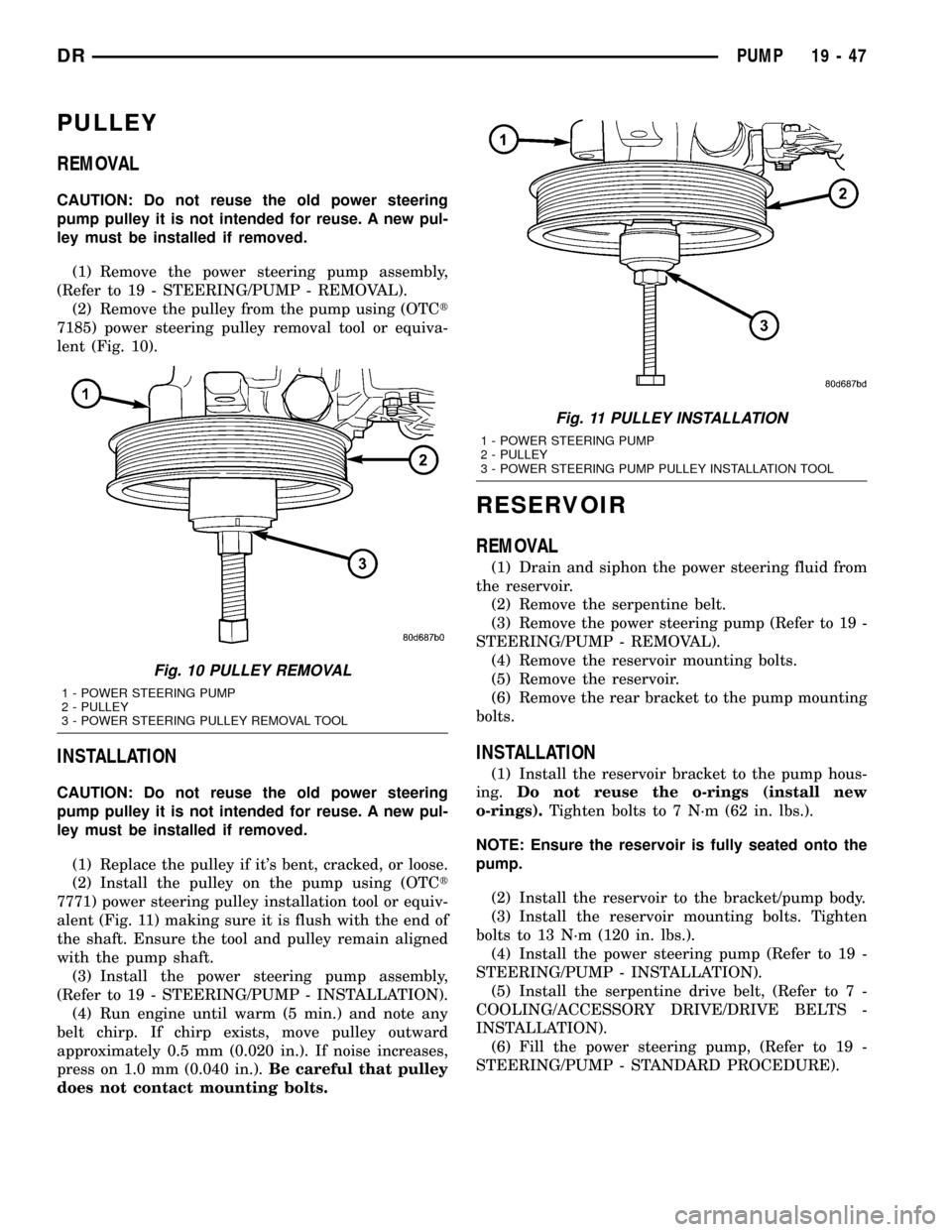
(2) Remove the pulley from the pump using (OTCt
7185) power steering pulley removal tool or equiva-
lent (Fig. 10).
INSTALLATION
CAUTION: Do not reuse the old power steering
pump pulley it is not intended for reuse. A new pul-
ley must be installed if removed.
(1) Replace the pulley if it's bent, cracked, or loose.
(2) Install the pulley on the pump using (OTCt
7771) power steering pulley installation tool or equiv-
alent (Fig. 11) making sure it is flush with the end of
the shaft. Ensure the tool and pulley remain aligned
with the pump shaft.
(3) Install the power steering pump assembly,
(Refer to 19 - STEERING/PUMP - INSTALLATION).
(4) Run engine until warm (5 min.) and note any
belt chirp. If chirp exists, move pulley outward
approximately 0.5 mm (0.020 in.). If noise increases,
press on 1.0 mm (0.040 in.).Be careful that pulley
does not contact mounting bolts.
RESERVOIR
REMOVAL
(1) Drain and siphon the power steering fluid from
the reservoir.
(2) Remove the serpentine belt.
(3) Remove the power steering pump (Refer to 19 -
STEERING/PUMP - REMOVAL).
(4) Remove the reservoir mounting bolts.
(5) Remove the reservoir.
(6) Remove the rear bracket to the pump mounting
bolts.
INSTALLATION
(1) Install the reservoir bracket to the pump hous-
ing.Do not reuse the o-rings (install new
o-rings).Tighten bolts to 7 N´m (62 in. lbs.).
NOTE: Ensure the reservoir is fully seated onto the
pump.
(2) Install the reservoir to the bracket/pump body.
(3) Install the reservoir mounting bolts. Tighten
bolts to 13 N´m (120 in. lbs.).
(4) Install the power steering pump (Refer to 19 -
STEERING/PUMP - INSTALLATION).
(5) Install the serpentine drive belt, (Refer to 7 -
COOLING/ACCESSORY DRIVE/DRIVE BELTS -
INSTALLATION).
(6) Fill the power steering pump, (Refer to 19 -
STEERING/PUMP - STANDARD PROCEDURE).
Fig. 10 PULLEY REMOVAL
1 - POWER STEERING PUMP
2 - PULLEY
3 - POWER STEERING PULLEY REMOVAL TOOL
Fig. 11 PULLEY INSTALLATION
1 - POWER STEERING PUMP
2 - PULLEY
3 - POWER STEERING PUMP PULLEY INSTALLATION TOOL
DRPUMP 19 - 47
Page 2344 of 2627
INSTRUMENT PANEL
TABLE OF CONTENTS
page page
CLUSTER BEZEL
REMOVAL.............................49
INSTALLATION.........................49
ASH RECEIVER
REMOVAL.............................50
INSTALLATION.........................51
CUP HOLDER
REMOVAL.............................51
INSTALLATION.........................51
GLOVE BOX
REMOVAL.............................52
INSTALLATION.........................52
GLOVE BOX LATCH
REMOVAL.............................52
INSTALLATION.........................52
INSTRUMENT PANEL ASSEMBLY
REMOVAL.............................52
INSTALLATION.........................55
INSTRUMENT PANEL HEADLAMP SWITCH
BEZEL
REMOVAL.............................56
INSTALLATION.........................56INSTRUMENT PANEL CENTER BEZEL
REMOVAL.............................57
INSTALLATION.........................57
INSTRUMENT PANEL DRIVER SIDE BEZEL
REMOVAL.............................58
INSTALLATION.........................58
INSTRUMENT PANEL TOP COVER
REMOVAL.............................58
INSTALLATION.........................59
INSTRUMENT PANEL LOWER SURROUND
REMOVAL.............................59
INSTALLATION.........................59
STEERING COLUMN OPENING COVER
REMOVAL.............................60
INSTALLATION.........................60
STEERING COLUMN OPENING SUPPORT
BRACKET
REMOVAL.............................60
INSTALLATION.........................60
STORAGE BIN
REMOVAL.............................61
INSTALLATION.........................61
CLUSTER BEZEL
REMOVAL
WARNING: ON VEHICLES EQUIPPED WITH AIR-
BAGS, DISABLE THE AIRBAG SYSTEM BEFORE
ATTEMPTING ANY STEERING WHEEL, STEERING
COLUMN, SEAT BELT TENSIONER, OR INSTRU-
MENT PANEL COMPONENT DIAGNOSIS OR SER-
VICE. DISCONNECT AND ISOLATE THE BATTERY
NEGATIVE (GROUND) CABLE, THEN WAIT TWO
MINUTES FOR THE AIRBAG SYSTEM CAPACITOR
TO DISCHARGE BEFORE PERFORMING FURTHER
DIAGNOSIS OR SERVICE. THIS IS THE ONLY SURE
WAY TO DISABLE THE AIRBAG SYSTEM. FAILURE
TO TAKE THE PROPER PRECAUTIONS COULD
RESULT IN ACCIDENTAL AIRBAG DEPLOYMENT
AND POSSIBLE PERSONAL INJURY.
(1) Remove the headlamp switch bezel. (Refer to
23 - BODY/INSTRUMENT PANEL/INSTRUMENT
PANEL SWITCH BEZEL - REMOVAL)
(2) Remove the center bezel. (Refer to 23 - BODY/
INSTRUMENT PANEL/INSTRUMENT PANEL
CENTER BEZEL - REMOVAL)(3) Remove the two top screws. (Fig. 1)
(4) Using a trim stick C-4755 or equivalent, sepa-
rate the two lower clips.
(5) Disengage the two top attachment bosses and
remove the bezel.
INSTALLATION
WARNING: ON VEHICLES EQUIPPED WITH AIR-
BAGS, DISABLE THE AIRBAG SYSTEM BEFORE
ATTEMPTING ANY STEERING WHEEL, STEERING
COLUMN, SEAT BELT TENSIONER, OR INSTRU-
MENT PANEL COMPONENT DIAGNOSIS OR SER-
VICE. DISCONNECT AND ISOLATE THE BATTERY
NEGATIVE (GROUND) CABLE, THEN WAIT TWO
MINUTES FOR THE AIRBAG SYSTEM CAPACITOR
TO DISCHARGE BEFORE PERFORMING FURTHER
DIAGNOSIS OR SERVICE. THIS IS THE ONLY SURE
WAY TO DISABLE THE AIRBAG SYSTEM. FAILURE
TO TAKE THE PROPER PRECAUTIONS COULD
RESULT IN ACCIDENTAL AIRBAG DEPLOYMENT
AND POSSIBLE PERSONAL INJURY.
(1) Position the cluster bezel over the cluster and
seat the outer bosses over the posts on the left and
right sides.
DRINSTRUMENT PANEL 23 - 49