1998 DODGE RAM 1500 Drive belt removal
[x] Cancel search: Drive belt removalPage 1367 of 2627
VIBRATION DAMPER
REMOVAL
(1) Disconnect negative cable from battery.
(2) Remove accessory drive belt (Refer to 7 -
COOLING/ACCESSORY DRIVE/DRIVE BELTS -
REMOVAL).
(3) Drain cooling system (Refer to 7 - COOLING -
STANDARD PROCEDURE).
(4) Remove radiator upper hose.
(5) Remove upper fan shroud.
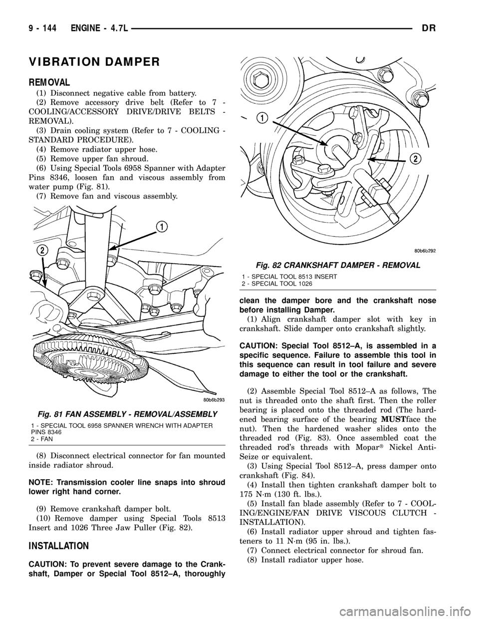
(6) Using Special Tools 6958 Spanner with Adapter
Pins 8346, loosen fan and viscous assembly from
water pump (Fig. 81).
(7) Remove fan and viscous assembly.
(8) Disconnect electrical connector for fan mounted
inside radiator shroud.
NOTE: Transmission cooler line snaps into shroud
lower right hand corner.
(9) Remove crankshaft damper bolt.
(10) Remove damper using Special Tools 8513
Insert and 1026 Three Jaw Puller (Fig. 82).
INSTALLATION
CAUTION: To prevent severe damage to the Crank-
shaft, Damper or Special Tool 8512±A, thoroughlyclean the damper bore and the crankshaft nose
before installing Damper.
(1) Align crankshaft damper slot with key in
crankshaft. Slide damper onto crankshaft slightly.
CAUTION: Special Tool 8512±A, is assembled in a
specific sequence. Failure to assemble this tool in
this sequence can result in tool failure and severe
damage to either the tool or the crankshaft.
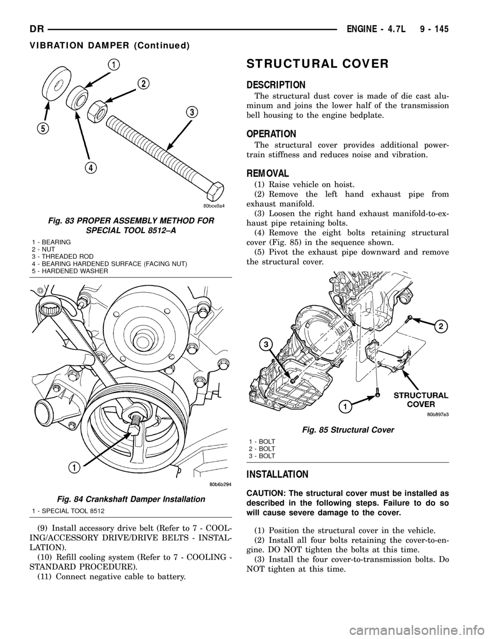
(2) Assemble Special Tool 8512±A as follows, The
nut is threaded onto the shaft first. Then the roller
bearing is placed onto the threaded rod (The hard-
ened bearing surface of the bearingMUSTface the
nut). Then the hardened washer slides onto the
threaded rod (Fig. 83). Once assembled coat the
threaded rod's threads with MopartNickel Anti-
Seize or equivalent.
(3) Using Special Tool 8512±A, press damper onto
crankshaft (Fig. 84).
(4) Install then tighten crankshaft damper bolt to
175 N´m (130 ft. lbs.).
(5) Install fan blade assembly (Refer to 7 - COOL-
ING/ENGINE/FAN DRIVE VISCOUS CLUTCH -
INSTALLATION).
(6) Install radiator upper shroud and tighten fas-
teners to 11 N´m (95 in. lbs.).
(7) Connect electrical connector for shroud fan.
(8) Install radiator upper hose.
Fig. 81 FAN ASSEMBLY - REMOVAL/ASSEMBLY
1 - SPECIAL TOOL 6958 SPANNER WRENCH WITH ADAPTER
PINS 8346
2-FAN
Fig. 82 CRANKSHAFT DAMPER - REMOVAL
1 - SPECIAL TOOL 8513 INSERT
2 - SPECIAL TOOL 1026
9 - 144 ENGINE - 4.7LDR
Page 1368 of 2627
(9) Install accessory drive belt (Refer to 7 - COOL-
ING/ACCESSORY DRIVE/DRIVE BELTS - INSTAL-
LATION).
(10) Refill cooling system (Refer to 7 - COOLING -
STANDARD PROCEDURE).
(11) Connect negative cable to battery.
STRUCTURAL COVER
DESCRIPTION
The structural dust cover is made of die cast alu-
minum and joins the lower half of the transmission
bell housing to the engine bedplate.
OPERATION
The structural cover provides additional power-
train stiffness and reduces noise and vibration.
REMOVAL
(1) Raise vehicle on hoist.
(2) Remove the left hand exhaust pipe from
exhaust manifold.
(3) Loosen the right hand exhaust manifold-to-ex-
haust pipe retaining bolts.
(4) Remove the eight bolts retaining structural
cover (Fig. 85) in the sequence shown.
(5) Pivot the exhaust pipe downward and remove
the structural cover.
INSTALLATION
CAUTION: The structural cover must be installed as
described in the following steps. Failure to do so
will cause severe damage to the cover.
(1) Position the structural cover in the vehicle.
(2) Install all four bolts retaining the cover-to-en-
gine. DO NOT tighten the bolts at this time.
(3) Install the four cover-to-transmission bolts. Do
NOT tighten at this time.
Fig. 83 PROPER ASSEMBLY METHOD FOR
SPECIAL TOOL 8512±A
1 - BEARING
2 - NUT
3 - THREADED ROD
4 - BEARING HARDENED SURFACE (FACING NUT)
5 - HARDENED WASHER
Fig. 84 Crankshaft Damper Installation
1 - SPECIAL TOOL 8512
Fig. 85 Structural Cover
1 - BOLT
2 - BOLT
3 - BOLT
DRENGINE - 4.7L 9 - 145
VIBRATION DAMPER (Continued)
Page 1384 of 2627
EXHAUST MANIFOLD
DESCRIPTION
The exhaust manifolds are log style with a pat-
ented flow enhancing design to maximize perfor-
mance. The exhaust manifolds are made of high
silicon molybdenum cast iron. A perforated core
graphite exhaust manifold gasket is used to improve
sealing to the cylinder head. The exhaust manifolds
are covered by a three layer laminated heat shield
for thermal protection and noise reduction. The heat
shields are fastened with a torque prevailing nut
that is backed off slightly to allow for the thermal
expansion of the exhaust manifold.
REMOVAL
RIGHT EXHAUST MANIFOLD
(1) Disconnect negative cable for battery.
(2) Remove air cleaner assembly, resonator assem-
bly and air inlet hose.
(3) Remove accessory drive belt (Refer to 7 -
COOLING/ACCESSORY DRIVE/DRIVE BELTS -
REMOVAL).
(4) Remove A/C compressor (Refer to 24 - HEAT-
ING & AIR CONDITIONING/PLUMBING/A/C COM-
PRESSOR - REMOVAL).
(5) Remove A/C accumulator support bracket fas-
tener.(6) Drain coolant below heater hose level (Refer to
7 - COOLING - STANDARD PROCEDURE).
(7) Remove heater hoses at engine.
(8) Remove fasteners attaching exhaust manifold
heat shield.
(9) Remove heat shield.
(10) Remove upper exhaust manifold attaching fas-
teners.
(11) Raise vehicle on hoist.
(12) Disconnect exhaust pipe from manifold.
(13) Remove fasteners attaching starter. Move
starter aside.
(14) Remove lower exhaust manifold attaching fas-
teners.
(15) Remove exhaust manifold and gasket (Fig.
110). Manifold is removed from below the engine
compartment.
DRENGINE - 4.7L 9 - 161
Page 1390 of 2627
sprocket assembly. A fixed chain guide and a hydrau-
lic oil damped tensioner are used to maintain tension
in each secondary chain system. The hydraulic ten-
sioners for the secondary chain systems are fed pres-
surized oil from oil reservoir pockets in the block.
Each tensioner also has a mechanical ratchet system
that limits chain slack if the tensioner piston bleeds
down after engine shut down. The tensioner arms
and guides also utilize nylon wear faces for low fric-
tion and long wear. The secondary timing chains
receive lubrication from a small orifice in the ten-
sioners. This orifice is protected from clogging by a
fine mesh screen which is located on the back of the
hydraulic tensioners.
STANDARD PROCEDURE
STANDARD PROCEDUREÐMEASURING
TIMING CHAIN WEAR
NOTE: This procedure must be performed with the
timing chain cover removed.
(1) Remove the timing chain cover. (Refer to 9 -
ENGINE/VALVE TIMING/TIMING BELT / CHAIN
COVER(S) - REMOVAL).
(2) To determine if the secondary timing chains
are worn, rotate the engine clockwise until maximum
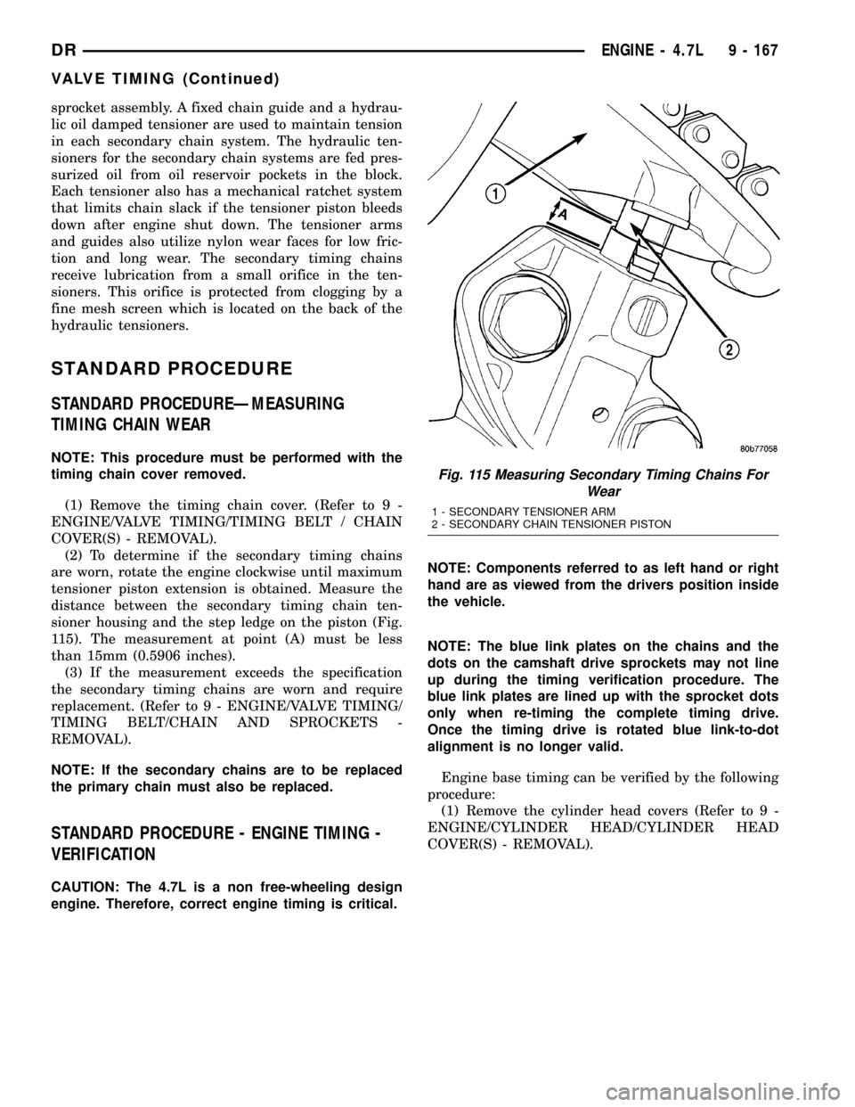
tensioner piston extension is obtained. Measure the
distance between the secondary timing chain ten-
sioner housing and the step ledge on the piston (Fig.
115). The measurement at point (A) must be less
than 15mm (0.5906 inches).
(3) If the measurement exceeds the specification
the secondary timing chains are worn and require
replacement. (Refer to 9 - ENGINE/VALVE TIMING/
TIMING BELT/CHAIN AND SPROCKETS -
REMOVAL).
NOTE: If the secondary chains are to be replaced
the primary chain must also be replaced.
STANDARD PROCEDURE - ENGINE TIMING -
VERIFICATION
CAUTION: The 4.7L is a non free-wheeling design
engine. Therefore, correct engine timing is critical.NOTE: Components referred to as left hand or right
hand are as viewed from the drivers position inside
the vehicle.
NOTE: The blue link plates on the chains and the
dots on the camshaft drive sprockets may not line
up during the timing verification procedure. The
blue link plates are lined up with the sprocket dots
only when re-timing the complete timing drive.
Once the timing drive is rotated blue link-to-dot
alignment is no longer valid.
Engine base timing can be verified by the following
procedure:
(1) Remove the cylinder head covers (Refer to 9 -
ENGINE/CYLINDER HEAD/CYLINDER HEAD
COVER(S) - REMOVAL).
Fig. 115 Measuring Secondary Timing Chains For
Wear
1 - SECONDARY TENSIONER ARM
2 - SECONDARY CHAIN TENSIONER PISTON
DRENGINE - 4.7L 9 - 167
VALVE TIMING (Continued)
Page 1393 of 2627
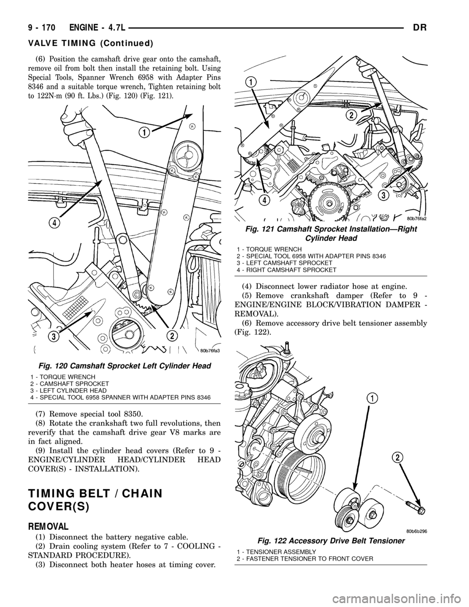
(6)Position the camshaft drive gear onto the camshaft,
remove oil from bolt then install the retaining bolt. Using
Special Tools, Spanner Wrench 6958 with Adapter Pins
8346 and a suitable torque wrench, Tighten retaining bolt
to 122N´m (90 ft. Lbs.) (Fig. 120) (Fig. 121).
(7) Remove special tool 8350.
(8) Rotate the crankshaft two full revolutions, then
reverify that the camshaft drive gear V8 marks are
in fact aligned.
(9) Install the cylinder head covers (Refer to 9 -
ENGINE/CYLINDER HEAD/CYLINDER HEAD
COVER(S) - INSTALLATION).
TIMING BELT / CHAIN
COVER(S)
REMOVAL
(1) Disconnect the battery negative cable.
(2) Drain cooling system (Refer to 7 - COOLING -
STANDARD PROCEDURE).
(3) Disconnect both heater hoses at timing cover.(4) Disconnect lower radiator hose at engine.
(5) Remove crankshaft damper (Refer to 9 -
ENGINE/ENGINE BLOCK/VIBRATION DAMPER -
REMOVAL).
(6) Remove accessory drive belt tensioner assembly
(Fig. 122).
Fig. 120 Camshaft Sprocket Left Cylinder Head
1 - TORQUE WRENCH
2 - CAMSHAFT SPROCKET
3 - LEFT CYLINDER HEAD
4 - SPECIAL TOOL 6958 SPANNER WITH ADAPTER PINS 8346
Fig. 121 Camshaft Sprocket InstallationÐRight
Cylinder Head
1 - TORQUE WRENCH
2 - SPECIAL TOOL 6958 WITH ADAPTER PINS 8346
3 - LEFT CAMSHAFT SPROCKET
4 - RIGHT CAMSHAFT SPROCKET
Fig. 122 Accessory Drive Belt Tensioner
1 - TENSIONER ASSEMBLY
2 - FASTENER TENSIONER TO FRONT COVER
9 - 170 ENGINE - 4.7LDR
VALVE TIMING (Continued)
Page 1394 of 2627
(7) Remove the generator and A/C compressor.
CAUTION: The 4.7L engine uses an RTV sealer
instead of a gasket to seal the front cover to the
engine block, from the factory. For service, MoparT
Engine RTV sealant must be substituted.
NOTE: It is not necessary to remove the water
pump for timing cover removal.
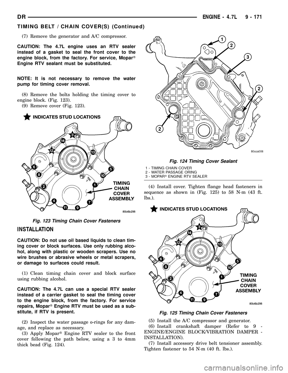
(8) Remove the bolts holding the timing cover to
engine block. (Fig. 123).
(9) Remove cover (Fig. 123).
INSTALLATION
CAUTION: Do not use oil based liquids to clean tim-
ing cover or block surfaces. Use only rubbing alco-
hol, along with plastic or wooden scrapers. Use no
wire brushes or abrasive wheels or metal scrapers,
or damage to surfaces could result.
(1) Clean timing chain cover and block surface
using rubbing alcohol.
CAUTION: The 4.7L can use a special RTV sealer
instead of a carrier gasket to seal the timing cover
to the engine block, from the factory. For service
repairs, MoparTEngine RTV must be used as a sub-
stitute, if RTV is present.
(2) Inspect the water passage o-rings for any dam-
age, and replace as necessary.
(3) Apply MopartEngine RTV sealer to the front
cover following the path below, usinga3to4mm
thick bead (Fig. 124).(4) Install cover. Tighten flange head fasteners in
sequence as shown in (Fig. 125) to 58 N´m (43 ft.
lbs.).
(5) Install the A/C compressor and generator.
(6) Install crankshaft damper (Refer to 9 -
ENGINE/ENGINE BLOCK/VIBRATION DAMPER -
INSTALLATION).
(7) Install accessory drive belt tensioner assembly.
Tighten fastener to 54 N´m (40 ft. lbs.).
Fig. 123 Timing Chain Cover Fasteners
Fig. 124 Timing Cover Sealant
1 - TIMING CHAIN COVER
2 - WATER PASSAGE ORING
3 - MOPARTENGINE RTV SEALER
Fig. 125 Timing Chain Cover Fasteners
DRENGINE - 4.7L 9 - 171
TIMING BELT / CHAIN COVER(S) (Continued)
Page 1413 of 2627
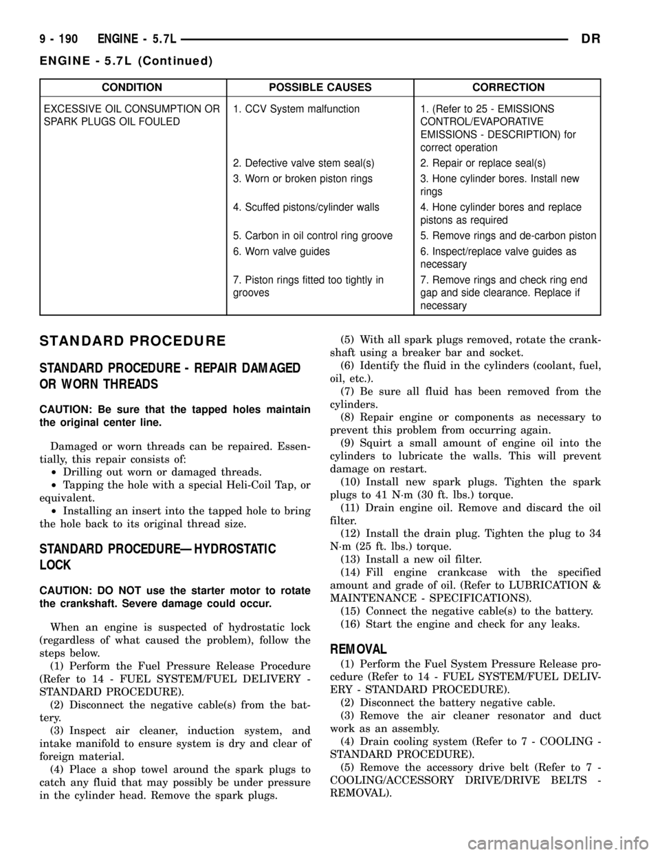
CONDITION POSSIBLE CAUSES CORRECTION
EXCESSIVE OIL CONSUMPTION OR
SPARK PLUGS OIL FOULED1. CCV System malfunction 1. (Refer to 25 - EMISSIONS
CONTROL/EVAPORATIVE
EMISSIONS - DESCRIPTION) for
correct operation
2. Defective valve stem seal(s) 2. Repair or replace seal(s)
3. Worn or broken piston rings 3. Hone cylinder bores. Install new
rings
4. Scuffed pistons/cylinder walls 4. Hone cylinder bores and replace
pistons as required
5. Carbon in oil control ring groove 5. Remove rings and de-carbon piston
6. Worn valve guides 6. Inspect/replace valve guides as
necessary
7. Piston rings fitted too tightly in
grooves7. Remove rings and check ring end
gap and side clearance. Replace if
necessary
STANDARD PROCEDURE
STANDARD PROCEDURE - REPAIR DAMAGED
OR WORN THREADS
CAUTION: Be sure that the tapped holes maintain
the original center line.
Damaged or worn threads can be repaired. Essen-
tially, this repair consists of:
²Drilling out worn or damaged threads.
²Tapping the hole with a special Heli-Coil Tap, or
equivalent.
²Installing an insert into the tapped hole to bring
the hole back to its original thread size.
STANDARD PROCEDUREÐHYDROSTATIC
LOCK
CAUTION: DO NOT use the starter motor to rotate
the crankshaft. Severe damage could occur.
When an engine is suspected of hydrostatic lock
(regardless of what caused the problem), follow the
steps below.
(1) Perform the Fuel Pressure Release Procedure
(Refer to 14 - FUEL SYSTEM/FUEL DELIVERY -
STANDARD PROCEDURE).
(2) Disconnect the negative cable(s) from the bat-
tery.
(3) Inspect air cleaner, induction system, and
intake manifold to ensure system is dry and clear of
foreign material.
(4) Place a shop towel around the spark plugs to
catch any fluid that may possibly be under pressure
in the cylinder head. Remove the spark plugs.(5) With all spark plugs removed, rotate the crank-
shaft using a breaker bar and socket.
(6) Identify the fluid in the cylinders (coolant, fuel,
oil, etc.).
(7) Be sure all fluid has been removed from the
cylinders.
(8) Repair engine or components as necessary to
prevent this problem from occurring again.
(9) Squirt a small amount of engine oil into the
cylinders to lubricate the walls. This will prevent
damage on restart.
(10) Install new spark plugs. Tighten the spark
plugs to 41 N´m (30 ft. lbs.) torque.
(11) Drain engine oil. Remove and discard the oil
filter.
(12) Install the drain plug. Tighten the plug to 34
N´m (25 ft. lbs.) torque.
(13) Install a new oil filter.
(14) Fill engine crankcase with the specified
amount and grade of oil. (Refer to LUBRICATION &
MAINTENANCE - SPECIFICATIONS).
(15) Connect the negative cable(s) to the battery.
(16) Start the engine and check for any leaks.
REMOVAL
(1) Perform the Fuel System Pressure Release pro-
cedure (Refer to 14 - FUEL SYSTEM/FUEL DELIV-
ERY - STANDARD PROCEDURE).
(2) Disconnect the battery negative cable.
(3) Remove the air cleaner resonator and duct
work as an assembly.
(4) Drain cooling system (Refer to 7 - COOLING -
STANDARD PROCEDURE).
(5) Remove the accessory drive belt (Refer to 7 -
COOLING/ACCESSORY DRIVE/DRIVE BELTS -
REMOVAL).
9 - 190 ENGINE - 5.7LDR
ENGINE - 5.7L (Continued)
Page 1414 of 2627
(6) Remove the viscous fan/drive (Refer to 7 -
COOLING/ENGINE/RADIATOR FAN - REMOVAL).
(7) Remove radiator (Refer to 7 - COOLING/EN-
GINE/RADIATOR - REMOVAL).
(8) Remove the upper crossmember and top core
support.
NOTE: It is not necessary to drain A/C system for
engine removal.
(9) Remove the A/C compressor with the lines
attached. Secure compressor out of the way.
(10) Remove generator assembly (Refer to 8 -
ELECTRICAL/CHARGING/GENERATOR -
REMOVAL).
(11) Remove the intake manifold and IAFM as an
assembly(Refer to 9 - ENGINE/MANIFOLDS/IN-
TAKE MANIFOLD - REMOVAL).
(12) Disconnect the heater hoses.
NOTE: It is not necessary to disconnect P/S hoses
from pump, for P/S pump removal.
(13) Remove the power steering pump and set
aside.
(14) Disconnect the fuel supply line (Refer to 14 -
FUEL SYSTEM/FUEL DELIVERY/QUICK CON-
NECT FITTING - STANDARD PROCEDURE).
(15) Raise and support the vehicle on a hoist and
drain the engine oil.
(16) Remove engine front mount thru-bolt nuts.
(17) Remove right side axle retaining bolts.
(18) Disconnect the transmission oil cooler lines
from their retainers at the oil pan bolts.
(19) Disconnect exhaust pipe at manifolds.
(20) Disconnect the starter wires. Remove starter
motor (Refer to 8 - ELECTRICAL/STARTING/
STARTER MOTOR - REMOVAL).
(21) Remove the structural dust cover and trans-
mission inspection cover,(Refer to 9 - ENGINE/EN-
GINE BLOCK/STRUCTURAL COVER - REMOVAL).
(22) Remove drive plate to converter bolts (Auto-
matic transmission equipped vehicles).
(23) Remove transmission bell housing to engine
block bolts.
(24) Lower the vehicle.
(25) Install engine lift fixture, special tool # 8984.
(26) Separate engine from transmission, remove
engine from vehicle, and install engine assembly on a
repair stand.
INSTALLATION
(1) Install engine lift fixture Special tool # 8984.
(2) Position the engine in the engine compartment.
(3) Lower engine into compartment and align
engine with transmission:²Manual Transmission: Align clutch disc assem-
bly (if disturbed). Install transmission input shaft
into clutch disc while mating engine and transmis-
sion surfaces. Install two transmission to engine
block mounting bolts finger tight.
²Automatic Transmission: Mate engine and trans-
mission and install two transmission to engine block
mounting bolts finger tight.
(4) Position the thru-bolt into the support cushion
brackets.
(5) Lower engine assembly until engine mount
through bolts rest in mount perches.
(6) Install remaining transmission to engine block
mounting bolts and tighten.
(7) Tighten engine mount through bolts.
(8) Install drive plate to torque converter bolts.
(Automatic transmission models)
(9) Install the structural dust cover and transmis-
sion dust cover,(Refer to 9 - ENGINE/ENGINE
BLOCK/STRUCTURAL COVER - INSTALLATION).
(10) Install the starter and connect the starter
wires (Refer to 8 - ELECTRICAL/STARTING/
STARTER MOTOR - INSTALLATION).
(11) Install exhaust pipe to manifold.
(12) Lower the vehicle.
(13) Remove engine lift fixture, special tool # 8984.
(14) Connect the fuel supply line (Refer to 14 -
FUEL SYSTEM/FUEL DELIVERY/QUICK CON-
NECT FITTING - STANDARD PROCEDURE).
(15) Reinstall the power steering pump.
(16) Connect the heater hoses.
(17) Install the intake manifold.
(18) Using a new gasket, install throttle body
(Refer to 14 - FUEL SYSTEM/FUEL INJECTION/
THROTTLE BODY - INSTALLATION).
(19) Install the generator and wire connections
(Refer to 8 - ELECTRICAL/CHARGING/GENERA-
TOR - INSTALLATION).
(20) Install a/c compressor and lines (Refer to 24 -
HEATING & AIR CONDITIONING/PLUMBING/A/C
COMPRESSOR - INSTALLATION).
(21) Install the accessory drive belt (Refer to 7 -
COOLING/ACCESSORY DRIVE/DRIVE BELTS -
INSTALLATION).
(22) Install upper radiator support crossmember.
(23) Install radiator (Refer to 7 - COOLING/EN-
GINE/RADIATOR - INSTALLATION).
(24) Connect the radiator lower hose.
(25) Connect the transmission oil cooler lines to
the radiator.
(26) Install the fan shroud.
(27) Install the fan (Refer to 7 - COOLING/EN-
GINE/RADIATOR FAN - INSTALLATION).
(28) Connect the radiator upper hose.
(29) Install the washer bottle.
(30) Connect the transmission cooler lines.
DRENGINE - 5.7L 9 - 191
ENGINE - 5.7L (Continued)