1998 DODGE RAM 1500 Alignment
[x] Cancel search: AlignmentPage 1535 of 2627
MUFFLER - 5.9L DIESEL
REMOVAL
(1) Disconnect the battery negative cables.
(2) Raise and support the vehicle.
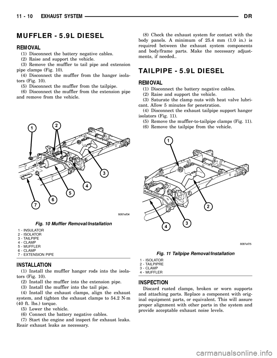
(3) Remove the muffler to tail pipe and extension
pipe clamps (Fig. 10).
(4) Disconnect the muffler from the hanger isola-
tors (Fig. 10).
(5) Disconnect the muffler from the tailpipe.
(6) Disconnect the muffler from the extension pipe
and remove from the vehicle.
INSTALLATION
(1) Install the muffler hanger rods into the isola-
tors (Fig. 10).
(2) Install the muffler into the extension pipe.
(3) Install the muffler into the tail pipe.
(4) Install the exhaust clamps, align the exhaust
system, and tighten the exhaust clamps to 54.2 N´m
(40 ft. lbs.) torque.
(5) Lower the vehicle.
(6) Connect the battery negative cables.
(7) Start the engine and inspect for exhaust leaks.
Reair exhaust leaks as necessary.(8) Check the exhaust system for contact with the
body panels. A minimum of 25.4 mm (1.0 in.) is
required between the exhaust system components
and body/frame parts. Make the necessary adjust-
ments, if needed..
TAILPIPE - 5.9L DIESEL
REMOVAL
(1) Disconnect the battery negative cables.
(2) Raise and support the vehicle.
(3) Saturate the clamp nuts with heat valve lubri-
cant. Allow 5 minutes for penetration.
(4) Disconnect the exhaust tailpipe support hanger
isolators (Fig. 11).
(5) Remove the muffler-to-tailpipe clamps (Fig. 11).
(6) Remove the tailpipe from the vehicle.
INSPECTION
Discard rusted clamps, broken or worn supports
and attaching parts. Replace a component with orig-
inal equipment parts, or equivalent. This will assure
proper alignment with other parts in the system and
provide acceptable exhaust noise levels.
Fig. 10 Muffler Removal/Installation
1 - INSULATOR
2 - ISOLATOR
3 - TAILPIPE
4 - CLAMP
5 - MUFFLER
6 - CLAMP
7 - EXTENSION PIPE
Fig. 11 Tailpipe Removal/Installation
1 - ISOLATOR
2 - TAILPIPRE
3 - CLAMP
4 - MUFFLER
11 - 10 EXHAUST SYSTEMDR
Page 1536 of 2627
INSTALLATION
(1) Install the tailpipe into the muffler.
(2) Install the tailpipe hanger rods into the isola-
tors (Fig. 11)
(3) Install the exhaust clamp, align the exhaust
system, and tighten the clamp 48 N´m (35 ft. lbs.)
torque.
(4) Lower the vehicle.
(5) Connect the battery negative cables.
(6) Start the engine and inspect for exhaust leaks.
Reair exhaust leaks as necessary.
(7) Check the exhaust system for contact with the
body panels. A minimum of 25.4 mm (1.0 in.) is
required between the exhaust system components
and body/frame parts. Make the necessary adjust-
ments, if needed..
TAILPIPE
REMOVAL
(1) Raise and support the vehicle.
(2) Saturate the clamp nuts with heat valve lubri-
cant. Allow 5 minutes for penetration.
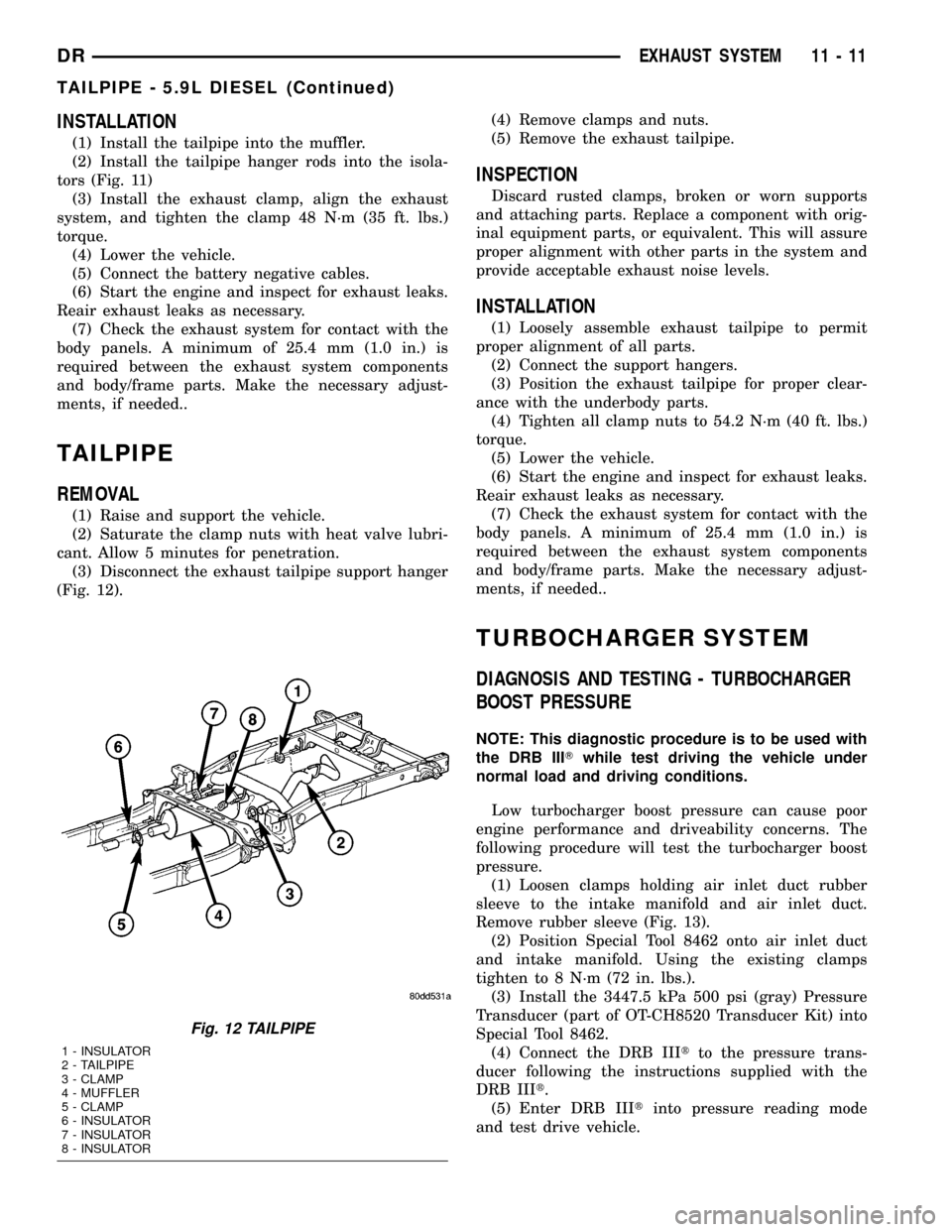
(3) Disconnect the exhaust tailpipe support hanger
(Fig. 12).(4) Remove clamps and nuts.
(5) Remove the exhaust tailpipe.
INSPECTION
Discard rusted clamps, broken or worn supports
and attaching parts. Replace a component with orig-
inal equipment parts, or equivalent. This will assure
proper alignment with other parts in the system and
provide acceptable exhaust noise levels.
INSTALLATION
(1) Loosely assemble exhaust tailpipe to permit
proper alignment of all parts.
(2) Connect the support hangers.
(3) Position the exhaust tailpipe for proper clear-
ance with the underbody parts.
(4) Tighten all clamp nuts to 54.2 N´m (40 ft. lbs.)
torque.
(5) Lower the vehicle.
(6) Start the engine and inspect for exhaust leaks.
Reair exhaust leaks as necessary.
(7) Check the exhaust system for contact with the
body panels. A minimum of 25.4 mm (1.0 in.) is
required between the exhaust system components
and body/frame parts. Make the necessary adjust-
ments, if needed..
TURBOCHARGER SYSTEM
DIAGNOSIS AND TESTING - TURBOCHARGER
BOOST PRESSURE
NOTE: This diagnostic procedure is to be used with
the DRB IIITwhile test driving the vehicle under
normal load and driving conditions.
Low turbocharger boost pressure can cause poor
engine performance and driveability concerns. The
following procedure will test the turbocharger boost
pressure.
(1) Loosen clamps holding air inlet duct rubber
sleeve to the intake manifold and air inlet duct.
Remove rubber sleeve (Fig. 13).
(2) Position Special Tool 8462 onto air inlet duct
and intake manifold. Using the existing clamps
tighten to 8 N´m (72 in. lbs.).
(3) Install the 3447.5 kPa 500 psi (gray) Pressure
Transducer (part of OT-CH8520 Transducer Kit) into
Special Tool 8462.
(4) Connect the DRB IIItto the pressure trans-
ducer following the instructions supplied with the
DRB IIIt.
(5) Enter DRB IIItinto pressure reading mode
and test drive vehicle.
Fig. 12 TAILPIPE
1 - INSULATOR
2 - TAILPIPE
3 - CLAMP
4 - MUFFLER
5 - CLAMP
6 - INSULATOR
7 - INSULATOR
8 - INSULATOR
DREXHAUST SYSTEM 11 - 11
TAILPIPE - 5.9L DIESEL (Continued)
Page 1545 of 2627
FRONT AIR DAM
REMOVAL
(1) Remove the two outboard screws.
(2) Remove the three middle screws and remove
the air dam.
INSTALLATION
(1) Position the air dam onto the bumper and seat
the carrot type fasteners fully.
(2) Starting at the center screw install the three
middle screws.
(3) Install the two outboard screws.
FRONT BUMPER
REMOVAL
(1) Using a grease pencil or equivalent, mark the
position of the bumper on the frame rail tip to aid
installation.
(2) Disconnect the fog lamp electrical connector at
the left frame rail.
(3) Support the bumper with a suitable lifting
device.
(4) Remove the center bracket nuts and bolts and
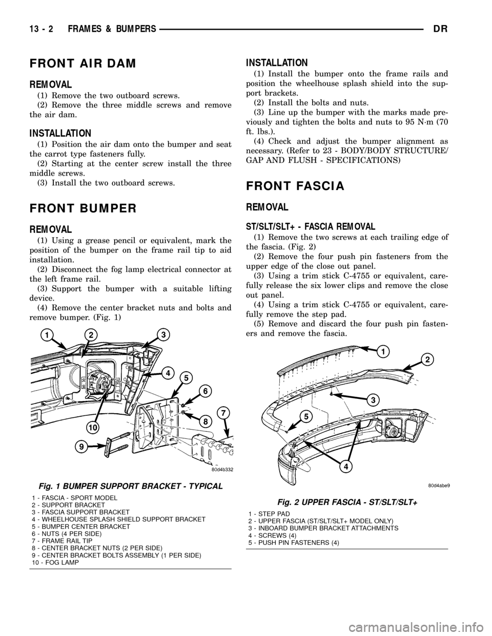
remove bumper. (Fig. 1)
INSTALLATION
(1) Install the bumper onto the frame rails and
position the wheelhouse splash shield into the sup-
port brackets.
(2) Install the bolts and nuts.
(3) Line up the bumper with the marks made pre-
viously and tighten the bolts and nuts to 95 N´m (70
ft. lbs.).
(4) Check and adjust the bumper alignment as
necessary. (Refer to 23 - BODY/BODY STRUCTURE/
GAP AND FLUSH - SPECIFICATIONS)
FRONT FASCIA
REMOVAL
ST/SLT/SLT+ - FASCIA REMOVAL
(1) Remove the two screws at each trailing edge of
the fascia. (Fig. 2)
(2) Remove the four push pin fasteners from the
upper edge of the close out panel.
(3) Using a trim stick C-4755 or equivalent, care-
fully release the six lower clips and remove the close
out panel.
(4) Using a trim stick C-4755 or equivalent, care-
fully remove the step pad.
(5) Remove and discard the four push pin fasten-
ers and remove the fascia.
Fig. 1 BUMPER SUPPORT BRACKET - TYPICAL
1 - FASCIA - SPORT MODEL
2 - SUPPORT BRACKET
3 - FASCIA SUPPORT BRACKET
4 - WHEELHOUSE SPLASH SHIELD SUPPORT BRACKET
5 - BUMPER CENTER BRACKET
6 - NUTS (4 PER SIDE)
7 - FRAME RAIL TIP
8 - CENTER BRACKET NUTS (2 PER SIDE)
9 - CENTER BRACKET BOLTS ASSEMBLY (1 PER SIDE)
10 - FOG LAMPFig. 2 UPPER FASCIA - ST/SLT/SLT+
1 - STEP PAD
2 - UPPER FASCIA (ST/SLT/SLT+ MODEL ONLY)
3 - INBOARD BUMPER BRACKET ATTACHMENTS
4 - SCREWS (4)
5 - PUSH PIN FASTENERS (4)
13 - 2 FRAMES & BUMPERSDR
Page 1549 of 2627
(14) Dress the cut edge of the existing frame in
preparation for the new rail tip.
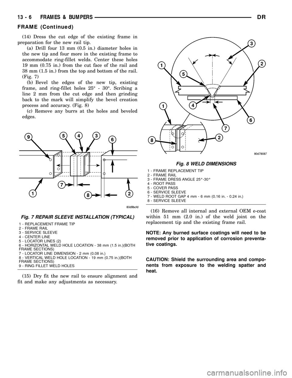
(a) Drill four 13 mm (0.5 in.) diameter holes in
the new tip and four more in the existing frame to
accommodate ring-fillet welds. Center these holes
19 mm (0.75 in.) from the cut face of the rail and
38 mm (1.5 in.) from the top and bottom of the rail.
(Fig. 7)
(b) Bevel the edges of the new tip, existing
frame, and ring-fillet holes 25É - 30É. Scribing a
line 2 mm from the cut edge and then grinding
back to the mark will simplify the bevel creation
process and accuracy. (Fig. 8)
(c) Remove any burrs at the holes and beveled
edges.
(15) Dry fit the new rail to ensure alignment and
fit and make any adjustments as necessary.(16) Remove all internal and external OEM e-coat
within 51 mm (2.0 in.) of the weld joint on the
replacement tip and the existing frame rail.
NOTE: Any burned surface coatings will need to be
removed prior to application of corrosion preventa-
tive coatings.
CAUTION: Shield the surrounding area and compo-
nents from exposure to the welding spatter and
heat.
Fig. 7 REPAIR SLEEVE INSTALLATION (TYPICAL)
1 - REPLACEMENT FRAME TIP
2 - FRAME RAIL
3 - SERVICE SLEEVE
4 - CENTER LINE
5 - LOCATOR LINES (2)
6 - HORIZONTAL WELD HOLE LOCATION - 38 mm (1.5 in.)(BOTH
FRAME SECTIONS)
7 - LOCATOR LINE DIMENSION-2mm(0.08 in.)
8 - VERTICAL WELD HOLE LOCATION - 19 mm (0.75 in.)(BOTH
FRAME SECTIONS)
9 - RING FILLET WELD HOLES
Fig. 8 WELD DIMENSIONS
1 - FRAME REPLACEMENT TIP
2 - FRAME RAIL
3 - FRAME DRESS ANGLE 25É-30É
4 - ROOT PASS
5 - COVER PASS
6 - SERVICE SLEEVE
7 - WELD ROOT GAP 4 mm-6mm(0.16 in. - 0.24 in.)
8 - SERVICE SLEEVE
13 - 6 FRAMES & BUMPERSDR
FRAME (Continued)
Page 1552 of 2627
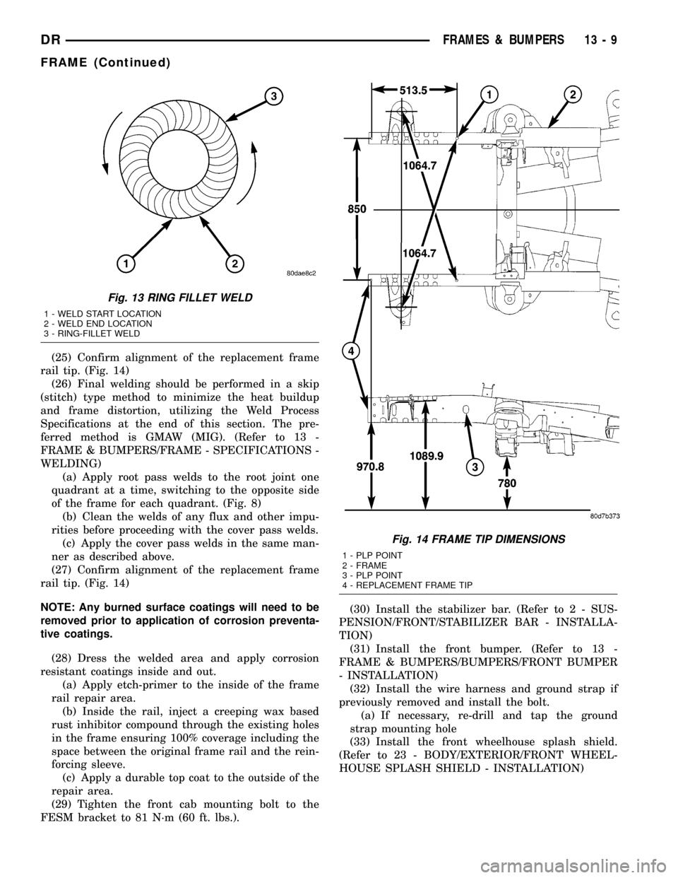
(25) Confirm alignment of the replacement frame
rail tip. (Fig. 14)
(26) Final welding should be performed in a skip
(stitch) type method to minimize the heat buildup
and frame distortion, utilizing the Weld Process
Specifications at the end of this section. The pre-
ferred method is GMAW (MIG). (Refer to 13 -
FRAME & BUMPERS/FRAME - SPECIFICATIONS -
WELDING)
(a) Apply root pass welds to the root joint one
quadrant at a time, switching to the opposite side
of the frame for each quadrant. (Fig. 8)
(b) Clean the welds of any flux and other impu-
rities before proceeding with the cover pass welds.
(c) Apply the cover pass welds in the same man-
ner as described above.
(27) Confirm alignment of the replacement frame
rail tip. (Fig. 14)
NOTE: Any burned surface coatings will need to be
removed prior to application of corrosion preventa-
tive coatings.
(28) Dress the welded area and apply corrosion
resistant coatings inside and out.
(a) Apply etch-primer to the inside of the frame
rail repair area.
(b) Inside the rail, inject a creeping wax based
rust inhibitor compound through the existing holes
in the frame ensuring 100% coverage including the
space between the original frame rail and the rein-
forcing sleeve.
(c) Apply a durable top coat to the outside of the
repair area.
(29) Tighten the front cab mounting bolt to the
FESM bracket to 81 N´m (60 ft. lbs.).(30) Install the stabilizer bar. (Refer to 2 - SUS-
PENSION/FRONT/STABILIZER BAR - INSTALLA-
TION)
(31) Install the front bumper. (Refer to 13 -
FRAME & BUMPERS/BUMPERS/FRONT BUMPER
- INSTALLATION)
(32) Install the wire harness and ground strap if
previously removed and install the bolt.
(a) If necessary, re-drill and tap the ground
strap mounting hole
(33) Install the front wheelhouse splash shield.
(Refer to 23 - BODY/EXTERIOR/FRONT WHEEL-
HOUSE SPLASH SHIELD - INSTALLATION)
Fig. 13 RING FILLET WELD
1 - WELD START LOCATION
2 - WELD END LOCATION
3 - RING-FILLET WELD
Fig. 14 FRAME TIP DIMENSIONS
1 - PLP POINT
2 - FRAME
3 - PLP POINT
4 - REPLACEMENT FRAME TIP
DRFRAMES & BUMPERS 13 - 9
FRAME (Continued)
Page 1581 of 2627
REMOVAL
WARNING: THE FUEL SYSTEM IS UNDER A CON-
STANT PRESSURE (EVEN WITH THE ENGINE OFF).
BEFORE SERVICING THE FUEL PUMP MODULE,
THE FUEL SYSTEM PRESSURE MUST BE
RELEASED.
(1) Drain and remove fuel tank. Refer to Fuel
Tank Removal/Installation.
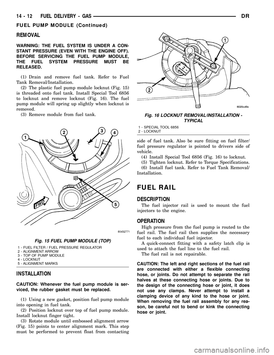
(2) The plastic fuel pump module locknut (Fig. 15)
is threaded onto fuel tank. Install Special Tool 6856
to locknut and remove locknut (Fig. 16). The fuel
pump module will spring up slightly when locknut is
removed.
(3) Remove module from fuel tank.
INSTALLATION
CAUTION: Whenever the fuel pump module is ser-
viced, the rubber gasket must be replaced.
(1) Using a new gasket, position fuel pump module
into opening in fuel tank.
(2) Position locknut over top of fuel pump module.
Install locknut finger tight.
(3) Rotate module until embossed alignment arrow
(Fig. 15) points to center alignment mark. This step
must be performed to prevent float from contactingside of fuel tank. Also be sure fitting on fuel filter/
fuel pressure regulator is pointed to drivers side of
vehicle.
(4) Install Special Tool 6856 (Fig. 16) to locknut.
(5) Tighten locknut. Refer to Torque Specifications.
(6) Install fuel tank. Refer to Fuel Tank Removal/
Installation.
FUEL RAIL
DESCRIPTION
The fuel injector rail is used to mount the fuel
injectors to the engine.
OPERATION
High pressure from the fuel pump is routed to the
fuel rail. The fuel rail then supplies the necessary
fuel to each individual fuel injector.
A quick-connect fitting with a safety latch clip is
used to attach the fuel line to the fuel rail.
The fuel rail is not repairable.
CAUTION: The left and right sections of the fuel rail
are connected with either a flexible connecting
hose, or joints. Do not attempt to separate the rail
halves at these connecting hose or joints. Due to
the design of the connecting hose or joint, it does
not use any clamps. Never attempt to install a
clamping device of any kind to the hose or joint.
When removing the fuel rail assembly for any rea-
son, be careful not to bend or kink the connecting
hose or joint.
Fig. 15 FUEL PUMP MODULE (TOP)
1 - FUEL FILTER / FUEL PRESSURE REGULATOR
2 - ALIGNMENT ARROW
3 - TOP OF PUMP MODULE
4 - LOCKNUT
5 - ALIGNMENT MARKS
Fig. 16 LOCKNUT REMOVAL/INSTALLATION -
TYPICAL
1 - SPECIAL TOOL 6856
2 - LOCKNUT
14 - 12 FUEL DELIVERY - GASDR
FUEL PUMP MODULE (Continued)
Page 1588 of 2627
INSTALLATION - EXCEPT DIESEL
(1) If fuel tank is to be replaced, install fuel pump
module into tank. Refer to Fuel Pump Module
Removal/Installation procedures.
(2) Disconnect clamps and remove rubber fuel fill
hose and fuel vent hose at fuel fill tube. Install these
2 hoses to 2 fuel tank fittings. Rotate hoses until
paint marks on hoses line up with alignment marks
(Fig. 26). Tighten both clamps.
(3) Position fuel tank to hydraulic jack.
(4) Raise tank until positioned near body.
(5) Connect EVAP line at tank (Fig. 1).
(6) Connect fuel pump module electrical connector
(Fig. 25) at top of tank.
(7) Connect fuel line quick-connect fitting to fuel
filter / fuel pressure regulator (Fig. 1) or (Fig. 25).
(8) Continue raising tank until positioned snug to
body.(9) Install and position both tank support straps.
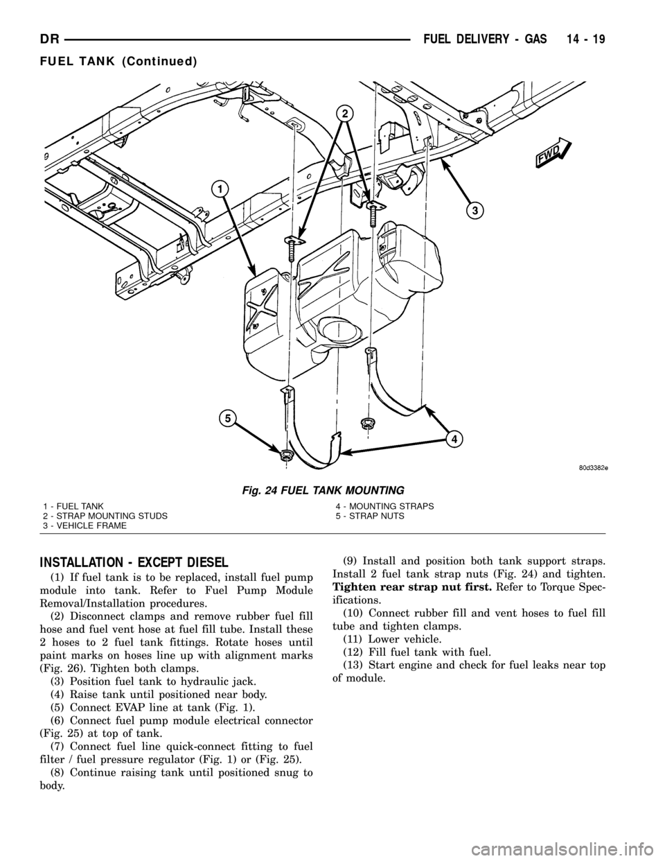
Install 2 fuel tank strap nuts (Fig. 24) and tighten.
Tighten rear strap nut first.Refer to Torque Spec-
ifications.
(10) Connect rubber fill and vent hoses to fuel fill
tube and tighten clamps.
(11) Lower vehicle.
(12) Fill fuel tank with fuel.
(13) Start engine and check for fuel leaks near top
of module.
Fig. 24 FUEL TANK MOUNTING
1 - FUEL TANK
2 - STRAP MOUNTING STUDS
3 - VEHICLE FRAME4 - MOUNTING STRAPS
5 - STRAP NUTS
DRFUEL DELIVERY - GAS 14 - 19
FUEL TANK (Continued)
Page 1589 of 2627
INLET FILTER
REMOVAL
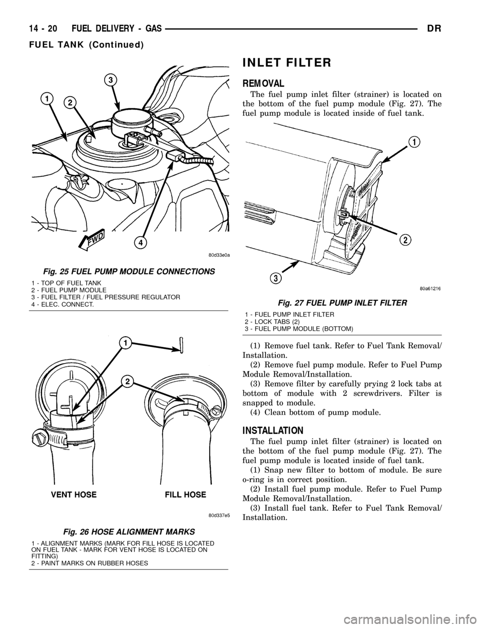
The fuel pump inlet filter (strainer) is located on
the bottom of the fuel pump module (Fig. 27). The
fuel pump module is located inside of fuel tank.
(1) Remove fuel tank. Refer to Fuel Tank Removal/
Installation.
(2) Remove fuel pump module. Refer to Fuel Pump
Module Removal/Installation.
(3) Remove filter by carefully prying 2 lock tabs at
bottom of module with 2 screwdrivers. Filter is
snapped to module.
(4) Clean bottom of pump module.
INSTALLATION
The fuel pump inlet filter (strainer) is located on
the bottom of the fuel pump module (Fig. 27). The
fuel pump module is located inside of fuel tank.
(1) Snap new filter to bottom of module. Be sure
o-ring is in correct position.
(2) Install fuel pump module. Refer to Fuel Pump
Module Removal/Installation.
(3) Install fuel tank. Refer to Fuel Tank Removal/
Installation.
Fig. 25 FUEL PUMP MODULE CONNECTIONS
1 - TOP OF FUEL TANK
2 - FUEL PUMP MODULE
3 - FUEL FILTER / FUEL PRESSURE REGULATOR
4 - ELEC. CONNECT.
Fig. 26 HOSE ALIGNMENT MARKS
1 - ALIGNMENT MARKS (MARK FOR FILL HOSE IS LOCATED
ON FUEL TANK - MARK FOR VENT HOSE IS LOCATED ON
FITTING)
2 - PAINT MARKS ON RUBBER HOSES
Fig. 27 FUEL PUMP INLET FILTER
1 - FUEL PUMP INLET FILTER
2 - LOCK TABS (2)
3 - FUEL PUMP MODULE (BOTTOM)
14 - 20 FUEL DELIVERY - GASDR
FUEL TANK (Continued)