1998 DODGE RAM 1500 coolant temperature
[x] Cancel search: coolant temperaturePage 1482 of 2627

INSTALLATION
(1) Install new valve seals. The yellow seals are for
the intake valves and the green seals are for the
exhaust valves.
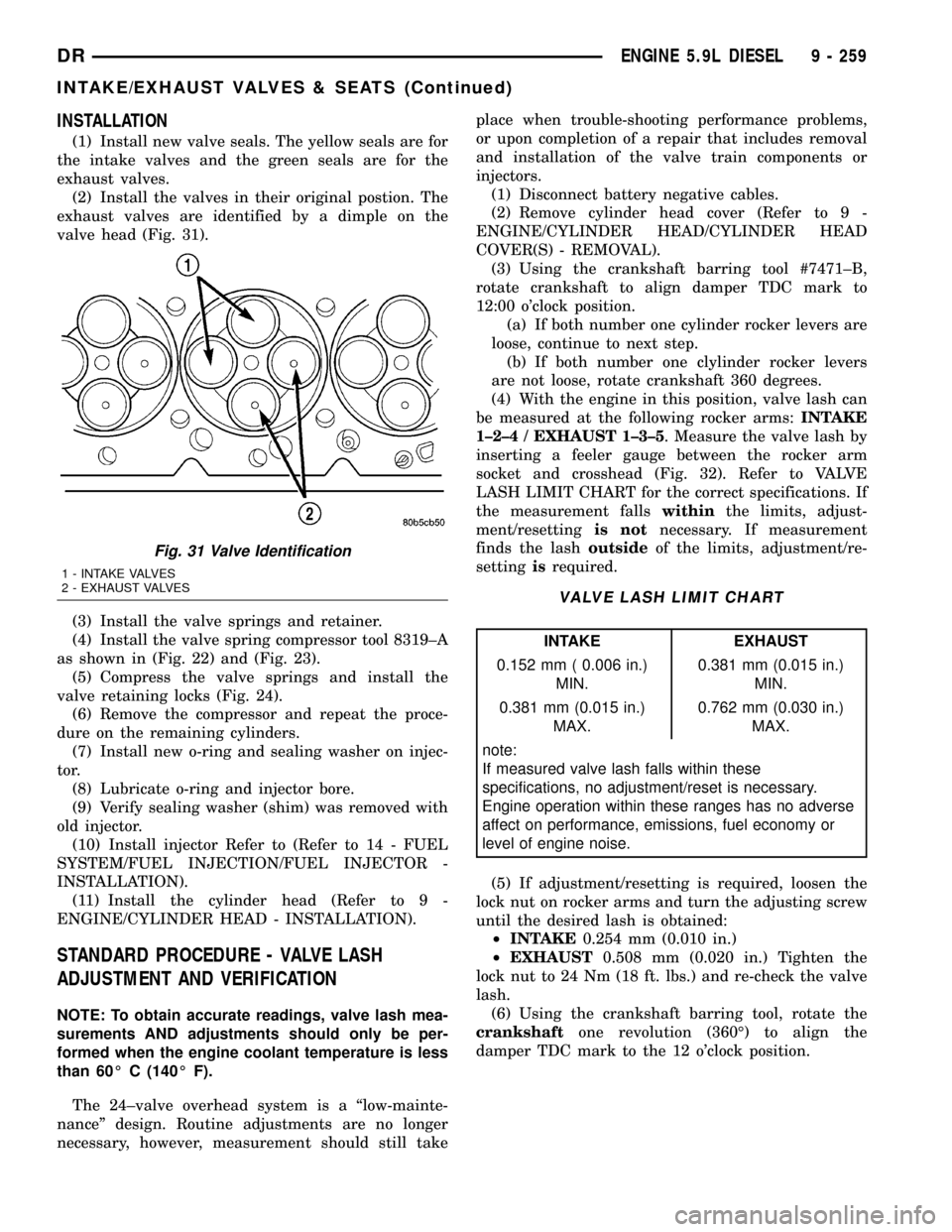
(2) Install the valves in their original postion. The
exhaust valves are identified by a dimple on the
valve head (Fig. 31).
(3) Install the valve springs and retainer.
(4) Install the valve spring compressor tool 8319±A
as shown in (Fig. 22) and (Fig. 23).
(5) Compress the valve springs and install the
valve retaining locks (Fig. 24).
(6) Remove the compressor and repeat the proce-
dure on the remaining cylinders.
(7) Install new o-ring and sealing washer on injec-
tor.
(8) Lubricate o-ring and injector bore.
(9) Verify sealing washer (shim) was removed with
old injector.
(10) Install injector Refer to (Refer to 14 - FUEL
SYSTEM/FUEL INJECTION/FUEL INJECTOR -
INSTALLATION).
(11) Install the cylinder head (Refer to 9 -
ENGINE/CYLINDER HEAD - INSTALLATION).
STANDARD PROCEDURE - VALVE LASH
ADJUSTMENT AND VERIFICATION
NOTE: To obtain accurate readings, valve lash mea-
surements AND adjustments should only be per-
formed when the engine coolant temperature is less
than 60É C (140É F).
The 24±valve overhead system is a ªlow-mainte-
nanceº design. Routine adjustments are no longer
necessary, however, measurement should still takeplace when trouble-shooting performance problems,
or upon completion of a repair that includes removal
and installation of the valve train components or
injectors.
(1) Disconnect battery negative cables.
(2) Remove cylinder head cover (Refer to 9 -
ENGINE/CYLINDER HEAD/CYLINDER HEAD
COVER(S) - REMOVAL).
(3) Using the crankshaft barring tool #7471±B,
rotate crankshaft to align damper TDC mark to
12:00 o'clock position.
(a) If both number one cylinder rocker levers are
loose, continue to next step.
(b) If both number one clylinder rocker levers
are not loose, rotate crankshaft 360 degrees.
(4) With the engine in this position, valve lash can
be measured at the following rocker arms:INTAKE
1±2±4 / EXHAUST 1±3±5. Measure the valve lash by
inserting a feeler gauge between the rocker arm
socket and crosshead (Fig. 32). Refer to VALVE
LASH LIMIT CHART for the correct specifications. If
the measurement fallswithinthe limits, adjust-
ment/resettingis notnecessary. If measurement
finds the lashoutsideof the limits, adjustment/re-
settingisrequired.
VALVE LASH LIMIT CHART
INTAKE EXHAUST
0.152 mm ( 0.006 in.)
MIN.0.381 mm (0.015 in.)
MIN.
0.381 mm (0.015 in.)
MAX.0.762 mm (0.030 in.)
MAX.
note:
If measured valve lash falls within these
specifications, no adjustment/reset is necessary.
Engine operation within these ranges has no adverse
affect on performance, emissions, fuel economy or
level of engine noise.
(5) If adjustment/resetting is required, loosen the
lock nut on rocker arms and turn the adjusting screw
until the desired lash is obtained:
²INTAKE0.254 mm (0.010 in.)
²EXHAUST0.508 mm (0.020 in.) Tighten the
lock nut to 24 Nm (18 ft. lbs.) and re-check the valve
lash.
(6) Using the crankshaft barring tool, rotate the
crankshaftone revolution (360É) to align the
damper TDC mark to the 12 o'clock position.
Fig. 31 Valve Identification
1 - INTAKE VALVES
2 - EXHAUST VALVES
DRENGINE 5.9L DIESEL 9 - 259
INTAKE/EXHAUST VALVES & SEATS (Continued)
Page 1572 of 2627

(2) Remove fuel pump relay from Power Distribu-
tion Center (PDC). For location of relay, refer to label
on underside of PDC cover.
(3) Start and run engine until it stalls.
(4) Attempt restarting engine until it will no
longer run.
(5) Turn ignition key to OFF position.
CAUTION: Steps 1, 2, 3 and 4 must be performed to
relieve high pressure fuel from within fuel rail. Do
not attempt to use following steps to relieve this
pressure as excessive fuel will be forced into a cyl-
inder chamber.
(6) Unplug connector from any fuel injector.
(7) Attach one end of a jumper wire with alligator
clips (18 gauge or smaller) to either injector terminal.
(8) Connect other end of jumper wire to positive
side of battery.(9) Connect one end of a second jumper wire to
remaining injector terminal.
CAUTION: Powering an injector for more than a few
seconds will permanently damage the injector.
(10) Momentarily touch other end of jumper wire
to negative terminal of battery for no more than a
few seconds.
(11) Place a rag or towel below fuel line quick-con-
nect fitting at fuel rail.
(12) Disconnect quick-connect fitting at fuel rail.
Refer to Quick-Connect Fittings.
(13) Return fuel pump relay to PDC.
(14) One or more Diagnostic Trouble Codes (DTC's)
may have been stored in PCM memory due to fuel
pump relay removal. The DRBtscan tool must be
used to erase a DTC.
SPECIFICATIONS
FUEL SYSTEM PRESSURE
58 psi +/- 2 psi
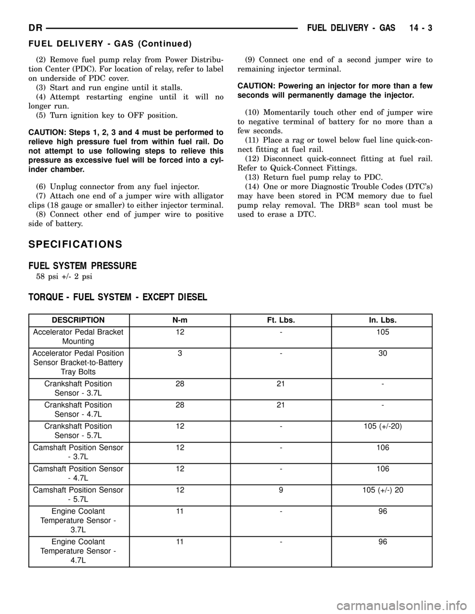
TORQUE - FUEL SYSTEM - EXCEPT DIESEL
DESCRIPTION N-m Ft. Lbs. In. Lbs.
Accelerator Pedal Bracket
Mounting12 - 105
Accelerator Pedal Position
Sensor Bracket-to-Battery
Tray Bolts3-30
Crankshaft Position
Sensor - 3.7L28 21 -
Crankshaft Position
Sensor - 4.7L28 21 -
Crankshaft Position
Sensor - 5.7L12 - 105 (+/-20)
Camshaft Position Sensor
- 3.7L12 - 106
Camshaft Position Sensor
- 4.7L12 - 106
Camshaft Position Sensor
- 5.7L12 9 105 (+/-) 20
Engine Coolant
Temperature Sensor -
3.7L11 - 9 6
Engine Coolant
Temperature Sensor -
4.7L11 - 9 6
DRFUEL DELIVERY - GAS 14 - 3
FUEL DELIVERY - GAS (Continued)
Page 1573 of 2627

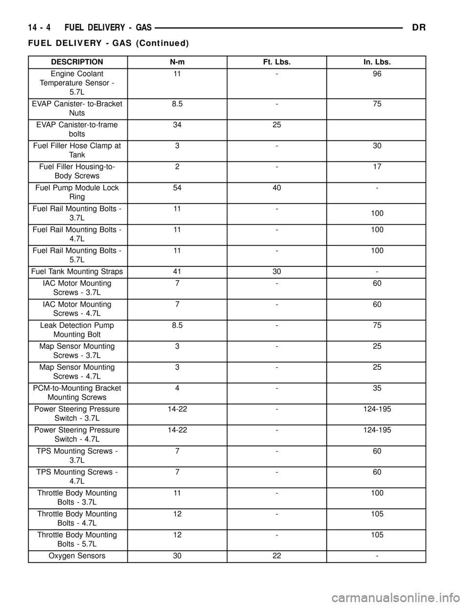
DESCRIPTION N-m Ft. Lbs. In. Lbs.
Engine Coolant
Temperature Sensor -
5.7L11 - 9 6
EVAP Canister- to-Bracket
Nuts8.5 - 75
EVAP Canister-to-frame
bolts34 25
Fuel Filler Hose Clamp at
Tank3-30
Fuel Filler Housing-to-
Body Screws2-17
Fuel Pump Module Lock
Ring54 40 -
Fuel Rail Mounting Bolts -
3.7L11 -
100
Fuel Rail Mounting Bolts -
4.7L11 - 100
Fuel Rail Mounting Bolts -
5.7L11 - 100
Fuel Tank Mounting Straps 41 30 -
IAC Motor Mounting
Screws - 3.7L7-60
IAC Motor Mounting
Screws - 4.7L7-60
Leak Detection Pump
Mounting Bolt8.5 - 75
Map Sensor Mounting
Screws - 3.7L3-25
Map Sensor Mounting
Screws - 4.7L3-25
PCM-to-Mounting Bracket
Mounting Screws4-35
Power Steering Pressure
Switch - 3.7L14-22 - 124-195
Power Steering Pressure
Switch - 4.7L14-22 - 124-195
TPS Mounting Screws -
3.7L7-60
TPS Mounting Screws -
4.7L7-60
Throttle Body Mounting
Bolts - 3.7L11 - 100
Throttle Body Mounting
Bolts - 4.7L12 - 105
Throttle Body Mounting
Bolts - 5.7L12 - 105
Oxygen Sensors 30 22 -
14 - 4 FUEL DELIVERY - GASDR
FUEL DELIVERY - GAS (Continued)
Page 1599 of 2627

INTAKE AIR TEMPERATURE
SENSOR
DESCRIPTION
The 2±wire Intake Manifold Air Temperature (IAT)
sensor is installed in the intake manifold with the
sensor element extending into the air stream.
The IAT sensor is a two-wire Negative Thermal
Coefficient (NTC) sensor. Meaning, as intake mani-
fold temperature increases, resistance (voltage) in the
sensor decreases. As temperature decreases, resis-
tance (voltage) in the sensor increases.
OPERATION
The IAT sensor provides an input voltage to the
Powertrain Control Module (PCM) indicating the
density of the air entering the intake manifold based
upon intake manifold temperature. At key-on, a
5±volt power circuit is supplied to the sensor from
the PCM. The sensor is grounded at the PCM
through a low-noise, sensor-return circuit.
The PCM uses this input to calculate the following:²Injector pulse-width
²Adjustment of spark timing (to help prevent
spark knock with high intake manifold air-charge
temperatures)
The resistance values of the IAT sensor is the same
as for the Engine Coolant Temperature (ECT) sensor.
REMOVAL
3.7L V-6
The intake manifold air temperature (IAT) sensor
is installed into the left side of intake manifold ple-
num (Fig. 16).
(1) Disconnect electrical connector from IAT sen-
sor.
(2) Clean dirt from intake manifold at sensor base.
(3) Gently lift on small plastic release tab (Fig. 16)
or (Fig. 17) and rotate sensor about 1/4 turn counter-
clockwise for removal.
(4) Check condition of sensor o-ring.
4.7L V-8
The intake manifold air temperature (IAT) sensor
is installed into the left side of intake manifold ple-
num (Fig. 18).
(1) Disconnect electrical connector from IAT sen-
sor.
(2) Clean dirt from intake manifold at sensor base.
Fig. 15 IDLE AIR CONTROL MOTOR - 4.7L V-8
1 - THROTTLE BODY
2 - TPS
3 - IAC MOTOR
4 - IAT SENSOR
5 - MOUNTING SCREWS
Fig. 16 IAT SENSOR LOCATION - 3.7L V-6
1 - IAT SENSOR
2 - RELEASE TAB
3 - ELECTRICAL CONNECTOR
14 - 30 FUEL INJECTION - GASDR
IDLE AIR CONTROL MOTOR (Continued)
Page 1615 of 2627

Fig. 1 DIESEL FUEL SYSTEM COMPONENTS
1 - ENGINE COOLANT TEMPERATURE (ECT) SENSOR 14 - FUEL SUPPLY LINE (LOW-PRESSURE, TO ENGINE)
2 - THROTTLE LEVER BELLCRANK AND APPS (ACCELERATOR
PEDAL POSITION SENSOR)15 - FUEL RETURN LINE CONNECTION (TO FUEL TANK)
3 - INTAKE MANIFOLD AIR HEATER/ELEMENTS 16 - FUEL DRAIN TUBE
4 - FUEL PRESSURE SENSOR 17 - OIL PRESSURE SWITCH
5 - FUEL PRESSURE LIMITING VALVE 18 - ENGINE CONTROL MODULE (ECM)
6 - HIGH-PRESSURE FUEL LINES 19 - FUEL INJECTION PUMP
7 - FUEL HEATER 20 - CRANKSHAFT POSITION (ENGINE SPEED) SENSOR
8 - HIGH-PRESSURE FUEL RAIL 21 - CAMSHAFT POSITION SENSOR (CMP)
9 - FUEL HEATER TEMPERATURE SENSOR (THERMOSTAT) 22 - FUEL CONTROL ACTUATOR (FCA)
10 - FUEL FILTER/WATER SEPARATOR 23 - CASCADE OVERFLOW VALVE
11 - FUEL TRANSFER (LIFT) PUMP
12 - FUEL DRAIN MANIFOLD (CYLINDER HEAD FUEL RETURN
LINE)
13 - DRAIN VALVE
14 - 46 FUEL DELIVERY - DIESELDR
FUEL DELIVERY - DIESEL (Continued)
Page 1617 of 2627

SPECIFICATIONS
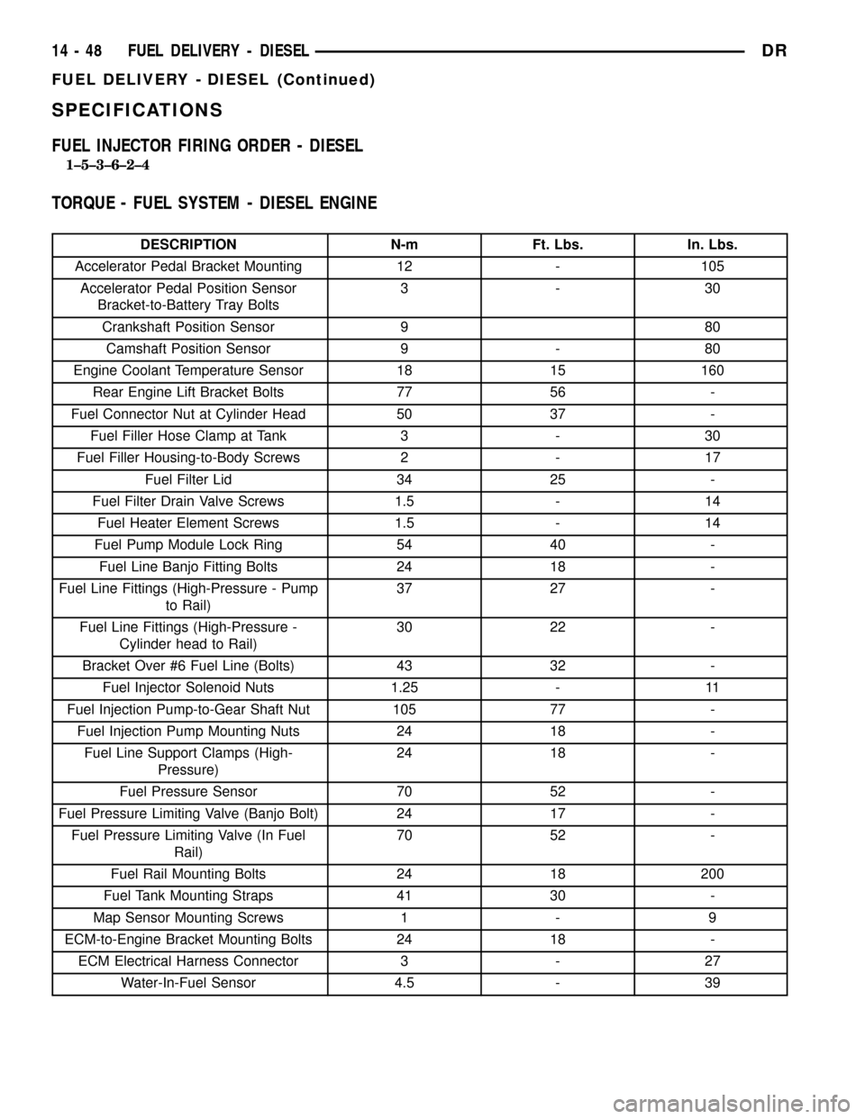
FUEL INJECTOR FIRING ORDER - DIESEL
1±5±3±6±2±4
TORQUE - FUEL SYSTEM - DIESEL ENGINE
DESCRIPTION N-m Ft. Lbs. In. Lbs.
Accelerator Pedal Bracket Mounting 12 - 105
Accelerator Pedal Position Sensor
Bracket-to-Battery Tray Bolts3-30
Crankshaft Position Sensor 9 80
Camshaft Position Sensor 9 - 80
Engine Coolant Temperature Sensor 18 15 160
Rear Engine Lift Bracket Bolts 77 56 -
Fuel Connector Nut at Cylinder Head 50 37 -
Fuel Filler Hose Clamp at Tank 3 - 30
Fuel Filler Housing-to-Body Screws 2 - 17
Fuel Filter Lid 34 25 -
Fuel Filter Drain Valve Screws 1.5 - 14
Fuel Heater Element Screws 1.5 - 14
Fuel Pump Module Lock Ring 54 40 -
Fuel Line Banjo Fitting Bolts 24 18 -
Fuel Line Fittings (High-Pressure - Pump
to Rail)37 27 -
Fuel Line Fittings (High-Pressure -
Cylinder head to Rail)30 22 -
Bracket Over #6 Fuel Line (Bolts) 43 32 -
Fuel Injector Solenoid Nuts 1.25 - 11
Fuel Injection Pump-to-Gear Shaft Nut 105 77 -
Fuel Injection Pump Mounting Nuts 24 18 -
Fuel Line Support Clamps (High-
Pressure)24 18 -
Fuel Pressure Sensor 70 52 -
Fuel Pressure Limiting Valve (Banjo Bolt) 24 17 -
Fuel Pressure Limiting Valve (In Fuel
Rail)70 52 -
Fuel Rail Mounting Bolts 24 18 200
Fuel Tank Mounting Straps 41 30 -
Map Sensor Mounting Screws 1 - 9
ECM-to-Engine Bracket Mounting Bolts 24 18 -
ECM Electrical Harness Connector 3 - 27
Water-In-Fuel Sensor 4.5 - 39
14 - 48 FUEL DELIVERY - DIESELDR
FUEL DELIVERY - DIESEL (Continued)
Page 1905 of 2627

(2) Heavy duty operation with a vehicle not prop-
erly equipped for this type of operation. Trailer tow-
ing or similar high load operation will overheat the
transmission fluid if the vehicle is improperly
equipped. Such vehicles should have an auxiliary
transmission fluid cooler, a heavy duty cooling sys-
tem, and the engine/axle ratio combination needed to
handle heavy loads.
DIAGNOSIS AND TESTING - FLUID
CONTAMINATION
Transmission fluid contamination is generally a
result of:
²adding incorrect fluid
²failure to clean dipstick and fill tube when
checking level
²engine coolant entering the fluid
²internal failure that generates debris
²overheat that generates sludge (fluid break-
down)
²failure to replace contaminated converter after
repair
The use of non-recommended fluids can result in
transmission failure. The usual results are erratic
shifts, slippage, abnormal wear and eventual failure
due to fluid breakdown and sludge formation. Avoid
this condition by using recommended fluids only.
The dipstick cap and fill tube should be wiped
clean before checking fluid level. Dirt, grease and
other foreign material on the cap and tube could fall
into the tube if not removed beforehand. Take the
time to wipe the cap and tube clean before withdraw-
ing the dipstick.
Engine coolant in the transmission fluid is gener-
ally caused by a cooler malfunction. The only remedy
is to replace the radiator as the cooler in the radiator
is not a serviceable part. If coolant has circulated
through the transmission, an overhaul is necessary.
The torque converter should also be replaced when-
ever a failure generates sludge and debris. This is
necessary because normal converter flushing proce-
dures will not remove all contaminants.
STANDARD PROCEDURE
STANDARD PROCEDURE - FLUID LEVEL
CHECK
Low fluid level can cause a variety of conditions
because it allows the pump to take in air along with
the fluid. As in any hydraulic system, air bubbles
make the fluid spongy, therefore, pressures will be
low and build up slowly.
Improper filling can also raise the fluid level too
high. When the transmssion has too much fluid, thegeartrain churns up foam and cause the same condi-
tions which occur with a low fluid level.
In either case, air bubbles can cause overheating
and/or fluid oxidation, and varnishing. This can
interfere with normal valve, clutch, and accumulator
operation. Foaming can also result in fluid escaping
from the transmission vent where it may be mis-
taken for a leak.
After the fluid has been checked, seat the dipstick
fully to seal out water and dirt.
The transmission has a dipstick to check oil level.
It is located on the right side of the engine. Be sure
to wipe all dirt from dipstick handle before removing.
Fluid level is checked with the engine running at
curb idle speed, the transmission in NEUTRAL and
the transmission fluid at normal operating tempera-
ture.The engine should be running at idle
speed for at least one minute, with the vehicle
on level ground.
The transmission fluid level can be checked two
ways.
PROCEDURE ONE
(1) Transmission fluid must be at normal operat-
ing temperature for accurate fluid level check. Drive
vehicle if necessary to bring fluid temperature up to
normal hot operating temperature of 82ÉC (180ÉF).
(2) Position vehicle on level surface.
(3) Start and run engine at curb idle speed.
(4) Apply parking brakes.
(5) Shift transmission momentarily into all gear
ranges. Then shift transmission back to NEUTRAL.
(6) Clean top of filler tube and dipstick to keep
dirt from entering tube.
(7) Remove dipstick (Fig. 87) and check fluid level
as follows:
(a) Correct acceptable level is in crosshatch area.
(b) Correct maximum level is to MAX arrow
mark.
(c) Incorrect level is at or below MIN line.
(d) If fluid is low, add only enough MopartAT F
+4 to restore correct level. Do not overfill.
Fig. 87 Dipstick Fluid Level Marks - Typical
1 - DIPSTICK
2 - MAXIMUM CORRECT FLUID LEVEL
3 - ACCEPTABLE FLUID LEVEL
21 - 202 AUTOMATIC TRANSMISSION - 48REDR
FLUID AND FILTER (Continued)
Page 2069 of 2627

FLUID AND FILTER
DIAGNOSIS AND TESTING
DIAGNOSIS AND TESTING - EFFECTS OF
INCORRECT FLUID LEVEL
A low fluid level allows the pump to take in air
along with the fluid. Air in the fluid will cause fluid
pressures to be low and develop slower than normal.
If the transmission is overfilled, the gears churn the
fluid into foam. This aerates the fluid and causing
the same conditions occurring with a low level. In
either case, air bubbles cause fluid overheating, oxi-
dation and varnish buildup which interferes with
valve and clutch operation. Foaming also causes fluid
expansion which can result in fluid overflow from the
transmission vent or fill tube. Fluid overflow can eas-
ily be mistaken for a leak if inspection is not careful.
DIAGNOSIS AND TESTING - CAUSES OF
BURNT FLUID
Burnt, discolored fluid is a result of overheating
which has three primary causes.
(1) Internal clutch slippage, usually caused by low
line pressure, inadequate clutch apply pressure, or
clutch seal failure.
(2) A result of restricted fluid flow through the
main and/or auxiliary cooler. This condition is usu-
ally the result of a faulty or improperly installed
drainback valve, a damaged main cooler, or severe
restrictions in the coolers and lines caused by debris
or kinked lines.
(3) Heavy duty operation with a vehicle not prop-
erly equipped for this type of operation. Trailer tow-
ing or similar high load operation will overheat the
transmission fluid if the vehicle is improperly
equipped. Such vehicles should have an auxiliary
transmission fluid cooler, a heavy duty cooling sys-
tem, and the engine/axle ratio combination needed to
handle heavy loads.
DIAGNOSIS AND TESTING - FLUID
CONTAMINATION
Transmission fluid contamination is generally a
result of:
²adding incorrect fluid
²failure to clean dipstick and fill tube when
checking level
²engine coolant entering the fluid
²internal failure that generates debris
²overheat that generates sludge (fluid break-
down)
²failure to replace contaminated converter after
repairThe use of non-recommended fluids can result in
transmission failure. The usual results are erratic
shifts, slippage, abnormal wear and eventual failure
due to fluid breakdown and sludge formation. Avoid
this condition by using recommended fluids only.
The dipstick cap and fill tube should be wiped
clean before checking fluid level. Dirt, grease and
other foreign material on the cap and tube could fall
into the tube if not removed beforehand. Take the
time to wipe the cap and tube clean before withdraw-
ing the dipstick.
Engine coolant in the transmission fluid is gener-
ally caused by a cooler malfunction. The only remedy
is to replace the radiator as the cooler in the radiator
is not a serviceable part. If coolant has circulated
through the transmission, an overhaul is necessary.
The torque converter should also be replaced when-
ever a failure generates sludge and debris. This is
necessary because normal converter flushing proce-
dures will not remove all contaminants.
STANDARD PROCEDURE
STANDARD PROCEDURE - FLUID LEVEL
CHECK
Low fluid level can cause a variety of conditions
because it allows the pump to take in air along with
the fluid. As in any hydraulic system, air bubbles
make the fluid spongy, therefore, pressures will be
low and build up slowly.
Improper filling can also raise the fluid level too
high. When the transmssion has too much fluid, the
geartrain churns up foam and cause the same condi-
tions which occur with a low fluid level.
In either case, air bubbles can cause overheating
and/or fluid oxidation, and varnishing. This can
interfere with normal valve, clutch, and accumulator
operation. Foaming can also result in fluid escaping
from the transmission vent where it may be mis-
taken for a leak.
After the fluid has been checked, seat the dipstick
fully to seal out water and dirt.
The transmission has a dipstick to check oil level.
It is located on the right side of the engine. Be sure
to wipe all dirt from dipstick handle before removing.
The torque converter fills in both the P (PARK)
and N (NEUTRAL) positions. Place the selector lever
in P (PARK) to be sure that the fluid level check is
accurate.The engine should be running at idle
speed for at least one minute, with the vehicle
on level ground.At normal operating temperature
(approximately 82 C. or 180 F.), the fluid level is cor-
rect if it is in the HOT region (cross-hatched area) on
the oil level indicator. The fluid level will be approx-
21 - 366 AUTOMATIC TRANSMISSION - 45RFE/545RFEDR