1998 DODGE RAM 1500 oil temperature
[x] Cancel search: oil temperaturePage 1463 of 2627
material to cure. This material is available in three
ounce tubes and has a shelf life of one year. After one
year this material will not properly cure. Always
inspect the package for the expiration date before
use.
MOPARtATF RTV
MopartATF RTV is a specifically designed black
silicone rubber RTV that retains adhesion and seal-
ing properties to seal components exposed to auto-
matic transmission fluid, engine coolants, and
moisture. This material is available in three ounce
tubes and has a shelf life of one year. After one year
this material will not properly cure. Always inspect
the package for the expiration date before use.
MOPARtGASKET MAKER
MopartGasket Maker is an anaerobic type gasket
material. The material cures in the absence of air
when squeezed between two metallic surfaces. It will
not cure if left in the uncovered tube. The anaerobic
material is for use between two machined surfaces.
Do not use on flexible metal flanges.
MOPARtGASKET SEALANT
MopartGasket Sealant is a slow drying, perma-
nently soft sealer. This material is recommended for
sealing threaded fittings and gaskets against leakage
of oil and coolant. Can be used on threaded and
machined parts under all temperatures. This mate-
rial is used on engines with multi-layer steel (MLS)
cylinder head gaskets. This material also will pre-
vent corrosion. MopartGasket Sealant is available in
a 13 oz. aerosol can or 4oz./16 oz. can w/applicator.
FORM-IN-PLACE GASKET AND SEALER
APPLICATION
Assembling parts using a form-in-place gasket
requires care but it's easier than using precut gas-
kets.
MopartGasket Maker material should be applied
sparingly 1 mm (0.040 in.) diameter or less of sealant
to one gasket surface. Be certain the material sur-
rounds each mounting hole. Excess material can eas-
ily be wiped off. Components should be torqued in
place within 15 minutes. The use of a locating dowel
is recommended during assembly to prevent smear-
ing material off the location.
MopartEngine RTV GEN II or ATF RTV gasket
material should be applied in a continuous bead
approximately 3 mm (0.120 in.) in diameter. All
mounting holes must be circled. For corner sealing, a
3.17 or 6.35 mm (1/8 or 1/4 in.) drop is placed in the
center of the gasket contact area. Uncured sealant
may be removed with a shop towel. Components
should be torqued in place while the sealant is still
wet to the touch (within 10 minutes). The usage of a
locating dowel is recommended during assembly to
prevent smearing material off the location.MopartGasket Sealant in an aerosol can should be
applied using a thin, even coat sprayed completely
over both surfaces to be joined, and both sides of a
gasket. Then proceed with assembly. Material in a
can w/applicator can be brushed on evenly over the
sealing surfaces. Material in an aerosol can should be
used on engines with multi-layer steel gaskets.
STANDARD PROCEDURE - REPAIR DAMAGED
OR WORN THREADS
CAUTION: Be sure that the tapped holes maintain
the original center line.
Damaged or worn threads can be repaired. Essen-
tially, this repair consists of:
²Drilling out worn or damaged threads.
²Tapping the hole with a special Heli-Coil Tap, or
equivalent.
²Installing an insert into the tapped hole to bring
the hole back to its original thread size.
STANDARD PROCEDUREÐHYDROSTATIC
LOCK
CAUTION: DO NOT use the starter motor to rotate
the crankshaft. Severe damage could occur.
When an engine is suspected of hydrostatic lock
(regardless of what caused the problem), follow the
steps below.
(1) Disconnect the negative cable(s) from the bat-
tery.
(2) Inspect air cleaner, induction system, and
intake manifold to ensure system is dry and clear of
foreign material.
(3) Place a shop towel around the fuel injectors to
catch any fluid that may possibly be under pressure
in the cylinder head. Remove the fuel injectors (Refer
to 14 - FUEL SYSTEM/FUEL INJECTION/FUEL
INJECTOR - REMOVAL).
(4) With all injectors removed, rotate the crank-
shaft using the crankshaft barring tool (PN 7471±B).
(5) Identify the fluid in the cylinders (coolant, fuel,
oil, etc.).
(6) Be sure all fluid has been removed from the
cylinders.
(7) Repair engine or components as necessary to
prevent this problem from occurring again.
(8) Squirt a small amount of engine oil into the
cylinders to lubricate the walls. This will prevent
damage on restart.
(9) Install fuel injectors (Refer to 14 - FUEL SYS-
TEM/FUEL INJECTION/FUEL INJECTOR -
INSTALLATION).
9 - 240 ENGINE 5.9L DIESELDR
ENGINE 5.9L DIESEL (Continued)
Page 1471 of 2627
ENGINE DATA PLATE
DESCRIPTION
The engine data plate contains specific information
that is helpful to servicing and obtaining parts for
the engine. The data plate can be found affixed to the
breather cover on the left side of the engine. Informa-
tion that can be found on the data plate includes:
²Date of Engine Manufacture
²Engine Serial Number
²Control Parts List (CPL)
²Engine Rated Horsepower
²Engine Firing Order
²Engine Displacement
²Valve Lash Reset Specifications
If the engine data plate is missing or not legible,
the engine serial number is used for engine identifi-
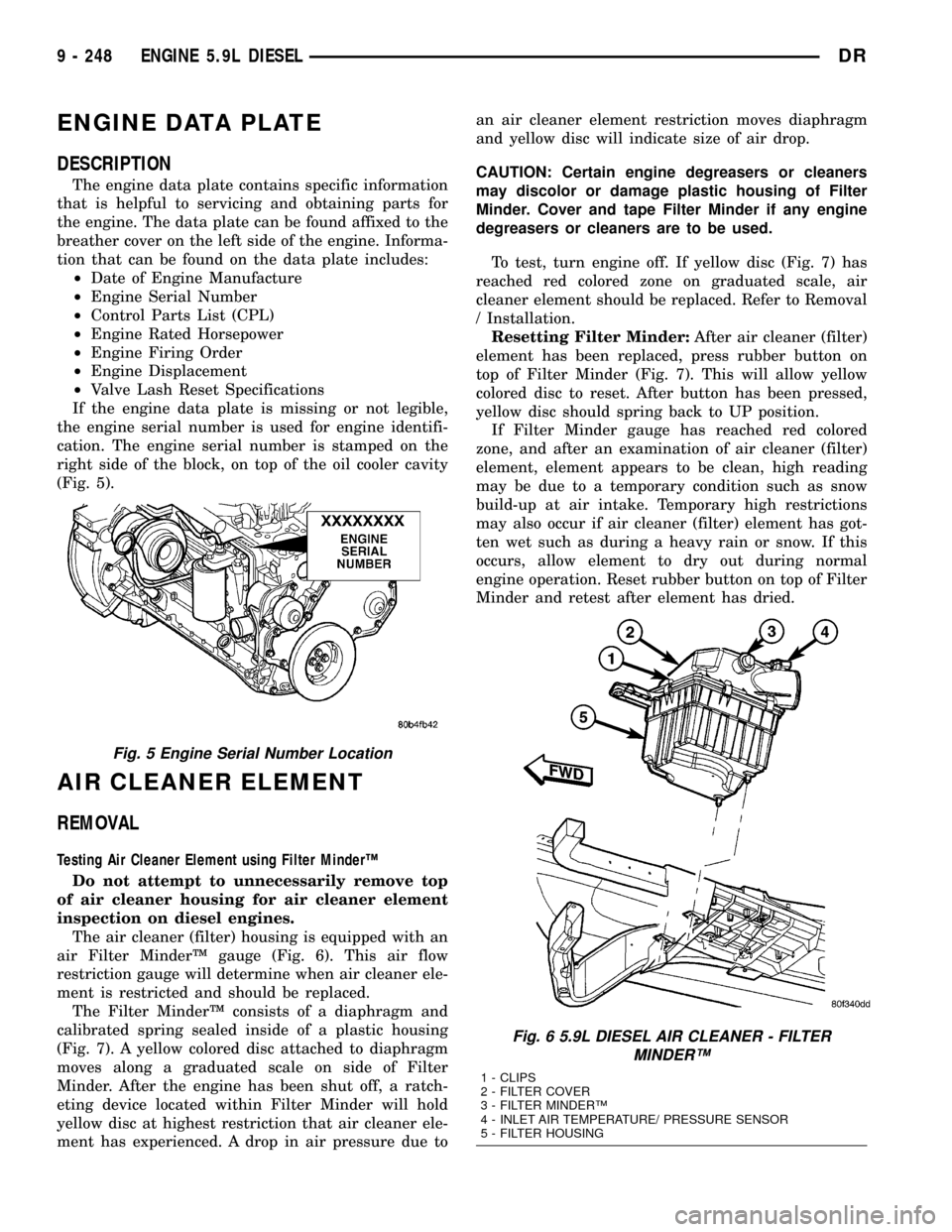
cation. The engine serial number is stamped on the
right side of the block, on top of the oil cooler cavity
(Fig. 5).
AIR CLEANER ELEMENT
REMOVAL
Testing Air Cleaner Element using Filter MinderŸ
Do not attempt to unnecessarily remove top
of air cleaner housing for air cleaner element
inspection on diesel engines.
The air cleaner (filter) housing is equipped with an
air Filter MinderŸ gauge (Fig. 6). This air flow
restriction gauge will determine when air cleaner ele-
ment is restricted and should be replaced.
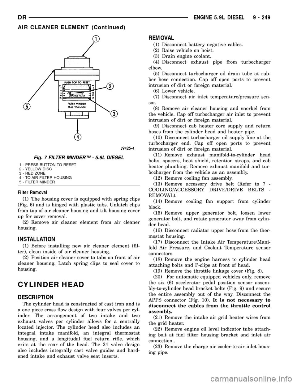
The Filter MinderŸ consists of a diaphragm and
calibrated spring sealed inside of a plastic housing
(Fig. 7). A yellow colored disc attached to diaphragm
moves along a graduated scale on side of Filter
Minder. After the engine has been shut off, a ratch-
eting device located within Filter Minder will hold
yellow disc at highest restriction that air cleaner ele-
ment has experienced. A drop in air pressure due toan air cleaner element restriction moves diaphragm
and yellow disc will indicate size of air drop.
CAUTION: Certain engine degreasers or cleaners
may discolor or damage plastic housing of Filter
Minder. Cover and tape Filter Minder if any engine
degreasers or cleaners are to be used.
To test, turn engine off. If yellow disc (Fig. 7) has
reached red colored zone on graduated scale, air
cleaner element should be replaced. Refer to Removal
/ Installation.
Resetting Filter Minder:After air cleaner (filter)
element has been replaced, press rubber button on
top of Filter Minder (Fig. 7). This will allow yellow
colored disc to reset. After button has been pressed,
yellow disc should spring back to UP position.
If Filter Minder gauge has reached red colored
zone, and after an examination of air cleaner (filter)
element, element appears to be clean, high reading
may be due to a temporary condition such as snow
build-up at air intake. Temporary high restrictions
may also occur if air cleaner (filter) element has got-
ten wet such as during a heavy rain or snow. If this
occurs, allow element to dry out during normal
engine operation. Reset rubber button on top of Filter
Minder and retest after element has dried.
Fig. 5 Engine Serial Number Location
Fig. 6 5.9L DIESEL AIR CLEANER - FILTER
MINDERŸ
1 - CLIPS
2 - FILTER COVER
3 - FILTER MINDERŸ
4 - INLET AIR TEMPERATURE/ PRESSURE SENSOR
5 - FILTER HOUSING
9 - 248 ENGINE 5.9L DIESELDR
Page 1472 of 2627
Filter Removal
(1) The housing cover is equipped with spring clips
(Fig. 6) and is hinged with plastic tabs. Unlatch clips
from top of air cleaner housing and tilt housing cover
up for cover removal.
(2) Remove air cleaner element from air cleaner
housing.
INSTALLATION
(1) Before installing new air cleaner element (fil-
ter), clean inside of air cleaner housing.
(2) Position air cleaner cover to tabs on front of air
cleaner housing. Latch spring clips to seal cover to
housing.
CYLINDER HEAD
DESCRIPTION
The cylinder head is constructed of cast iron and is
a one piece cross flow design with four valves per cyl-
inder. The arrangement of two intake and two
exhaust valves per cylinder allows for a centrally
located injector. The cylinder head also includes an
integral intake manifold, an integral thermostat
housing, and a longitudal fuel return rifle, which
exits at the rear of the head. The 24 valve design
also includes integrally cast valve guides and hard-
ened intake and exhaust valve seat inserts.
REMOVAL
(1) Disconnect battery negative cables.
(2) Raise vehicle on hoist.
(3) Drain engine coolant.
(4) Disconnect exhaust pipe from turbocharger
elbow.
(5) Disconnect turbocharger oil drain tube at rub-
ber hose connection. Cap off open ports to prevent
intrusion of dirt or foreign material.
(6) Lower vehicle.
(7) Disconnect air inlet temperature/pressure sen-
sor.
(8) Remove air cleaner housing and snorkel from
the vehicle. Cap off turbocharger air inlet to prevent
intrusion of dirt or foreign material.
(9) Disconnect cab heater core supply and return
hoses from the cylinder head and heater pipe.
(10) Disconnect turbocharger oil supply line at the
turbocharger end. Cap off open ports to prevent
intrusion of dirt or foreign material.
(11) Remove exhaust manifold-to-cylinder head
bolts, spacers, heat shield, retention straps, and cab
heater plumbing. Remove exhaust manifold and tur-
bocharger from the vehicle as an assembly.
(12) Remove cooling fan assembly.
(13) Remove accessory drive belt (Refer to 7 -
COOLING/ACCESSORY DRIVE/DRIVE BELTS -
REMOVAL).
(14) Remove cooling fan support from cylinder
block.
(15) Remove upper generator bolt, loosen lower
generator bolt, and rotate generator away from cylin-
der head.
(16) Disconnect radiator upper hose from the ther-
mostat housing.
(17) Disconnect the Intake Air Temperature/Mani-
fold Air Pressure, and Coolant Temperature sensor
connectors.
(18) Remove the engine harness to cylinder head
attaching bolts and P-clips at front of head.
(19) Remove the throttle linkage cover (Fig. 8).
(20) For automatic equipped vehicles only, remove
the six (6) accelerator pedal position sensor assem-
bly-to-cylinder head bracket bolts (Fig. 9) and secure
the entire assembly out of the way. Disconnect the
APPS connector (Fig. 10).It is not necessary to
disconnect the cables from the throttle control
assembly.
(21) Remove the intake air grid heater wires from
the grid heater.
(22) Remove engine oil level indicator tube attach-
ing bolt at fuel filter housing bracket and inlet air
connection..
(23) Remove the charge air cooler-to-air inlet hous-
ing pipe.
Fig. 7 FILTER MINDERŸ - 5.9L DIESEL
1 - PRESS BUTTON TO RESET
2 - YELLOW DISC
3 - RED ZONE
4 - TO AIR FILTER HOUSING
5 - FILTER MINDER
DRENGINE 5.9L DIESEL 9 - 249
AIR CLEANER ELEMENT (Continued)
Page 1477 of 2627
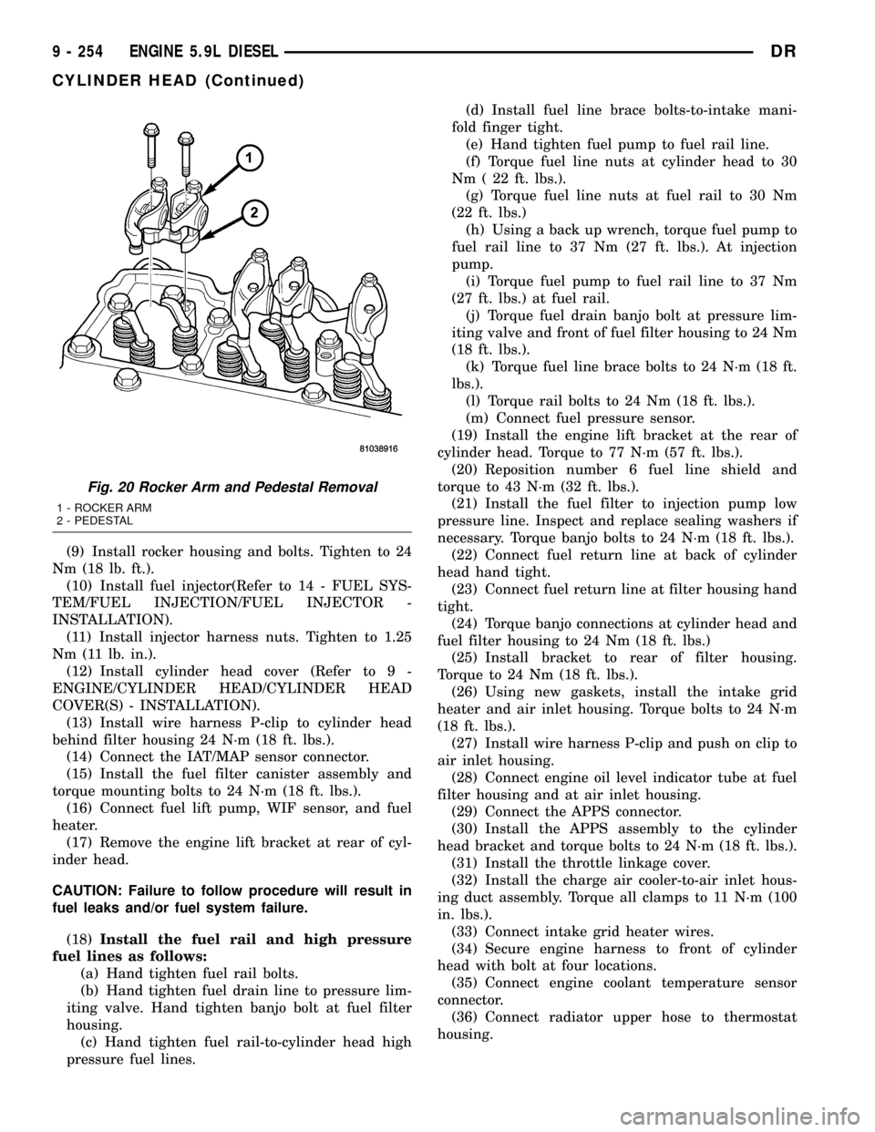
(9) Install rocker housing and bolts. Tighten to 24
Nm (18 lb. ft.).
(10) Install fuel injector(Refer to 14 - FUEL SYS-
TEM/FUEL INJECTION/FUEL INJECTOR -
INSTALLATION).
(11) Install injector harness nuts. Tighten to 1.25
Nm (11 lb. in.).
(12) Install cylinder head cover (Refer to 9 -
ENGINE/CYLINDER HEAD/CYLINDER HEAD
COVER(S) - INSTALLATION).
(13) Install wire harness P-clip to cylinder head
behind filter housing 24 N´m (18 ft. lbs.).
(14) Connect the IAT/MAP sensor connector.
(15) Install the fuel filter canister assembly and
torque mounting bolts to 24 N´m (18 ft. lbs.).
(16) Connect fuel lift pump, WIF sensor, and fuel
heater.
(17) Remove the engine lift bracket at rear of cyl-
inder head.
CAUTION: Failure to follow procedure will result in
fuel leaks and/or fuel system failure.
(18)Install the fuel rail and high pressure
fuel lines as follows:
(a) Hand tighten fuel rail bolts.
(b) Hand tighten fuel drain line to pressure lim-
iting valve. Hand tighten banjo bolt at fuel filter
housing.
(c) Hand tighten fuel rail-to-cylinder head high
pressure fuel lines.(d) Install fuel line brace bolts-to-intake mani-
fold finger tight.
(e) Hand tighten fuel pump to fuel rail line.
(f) Torque fuel line nuts at cylinder head to 30
Nm ( 22 ft. lbs.).
(g) Torque fuel line nuts at fuel rail to 30 Nm
(22 ft. lbs.)
(h) Using a back up wrench, torque fuel pump to
fuel rail line to 37 Nm (27 ft. lbs.). At injection
pump.
(i) Torque fuel pump to fuel rail line to 37 Nm
(27 ft. lbs.) at fuel rail.
(j) Torque fuel drain banjo bolt at pressure lim-
iting valve and front of fuel filter housing to 24 Nm
(18 ft. lbs.).
(k) Torque fuel line brace bolts to 24 N´m (18 ft.
lbs.).
(l) Torque rail bolts to 24 Nm (18 ft. lbs.).
(m) Connect fuel pressure sensor.
(19) Install the engine lift bracket at the rear of
cylinder head. Torque to 77 N´m (57 ft. lbs.).
(20) Reposition number 6 fuel line shield and
torque to 43 N´m (32 ft. lbs.).
(21) Install the fuel filter to injection pump low
pressure line. Inspect and replace sealing washers if
necessary. Torque banjo bolts to 24 N´m (18 ft. lbs.).
(22) Connect fuel return line at back of cylinder
head hand tight.
(23) Connect fuel return line at filter housing hand
tight.
(24) Torque banjo connections at cylinder head and
fuel filter housing to 24 Nm (18 ft. lbs.)
(25) Install bracket to rear of filter housing.
Torque to 24 Nm (18 ft. lbs.).
(26) Using new gaskets, install the intake grid
heater and air inlet housing. Torque bolts to 24 N´m
(18 ft. lbs.).
(27) Install wire harness P-clip and push on clip to
air inlet housing.
(28) Connect engine oil level indicator tube at fuel
filter housing and at air inlet housing.
(29) Connect the APPS connector.
(30) Install the APPS assembly to the cylinder
head bracket and torque bolts to 24 N´m (18 ft. lbs.).
(31) Install the throttle linkage cover.
(32) Install the charge air cooler-to-air inlet hous-
ing duct assembly. Torque all clamps to 11 N´m (100
in. lbs.).
(33) Connect intake grid heater wires.
(34) Secure engine harness to front of cylinder
head with bolt at four locations.
(35) Connect engine coolant temperature sensor
connector.
(36) Connect radiator upper hose to thermostat
housing.
Fig. 20 Rocker Arm and Pedestal Removal
1 - ROCKER ARM
2 - PEDESTAL
9 - 254 ENGINE 5.9L DIESELDR
CYLINDER HEAD (Continued)
Page 1478 of 2627
(37) Rotate generator into position. Install upper
bolt and torque upper and lower bolts.
(38)
Install wire harness push-on clip below bracket.
(39) Install wire harness P-clip to top of bracket.
(40) Install fan support and torque to 32 N´m (24
ft. lbs.).
(41) Install cooling fan/drive refer to (Refer to 7 -
COOLING/ENGINE/RADIATOR FAN - INSTALLA-
TION).
(42) Install accessory drive belt (Refer to 7 -
COOLING/ACCESSORY DRIVE/DRIVE BELTS -
INSTALLATION).
(43) Install exhaust manifold/turbocharger assem-
bly, using new gaskets. Start all bolts/spacers by
hand. Torque bolts to 43 N´m (32 ft. lbs.).
(44) Install exhaust manifold heat shield to
exhaust manifold studs. Install retaining nuts.Torque
to 15 N´m (11 ft. lbs.).
(45) Install exhaust bolt retention straps across
cylinders5&6.
(46) Connect turbocharger oil drain tube. Torque
clamp to 8 N´m (71 in. lbs.).
(47) Perform the turbocharger pre-lube procedure.
Refer to Group 11, Exhaust System and Turbo-
charger for the correct procedure.
(48) Connect the turbocharger oil supply line.
Torque to 24 N´m (18 ft. lbs.).
(49) Install air cleaner housing and duct.
(50) Connect air inlet temperature/pressure sensor.
(51) Raise vehicle on hoist.
(52) Install exhaust pipe to turbocharger elbow.
Torque bolts to 11 N´m (100 in. lbs.).
(53) Lower vehicle.
(54) Fill engine coolant (Refer to 7 - COOLING -
STANDARD PROCEDURE).
(55) Start engine and check for leaks.
CYLINDER HEAD COVER(S)
REMOVAL
REMOVALÐCYLINDER HEAD COVER
(1) Disconnect both battery negative cables.
(2) Remove oil fill cap.
(3) Remove the breather cover.
(4) Disconnect the breather hose and breather
drain tube from the breather housing.
(5) Remove cylinder head cover bolts.
(6) Remove the cylinder head cover.
REMOVALÐROCKER HOUSING
(1) Remove cylinder head cover as outlined in this
section.
(2) Disconnect rocker housing injector harness con-
nectors.(3) Remove injector harness nuts from injectors.
(4) Remove rocker housing bolts.
(5) Remove rocker housing and gasket.
CLEANING
Using a suitable solvent, Clean and dry gasket
mating surfaces on cylinder head and rocker housing.
Wipe gasket dry and inspect for re-use.
INSPECTION
The cylinder head cover gasket and rocker hous-
ing gasket, are reusable.However, should cracks,
nicks, or tears be present in the rubber/silicone construc-
tion, the defective components should be replaced. Also
replace gasket if it is no longer flexible. Inspect o-rings
on cylinder head cover bolts.Do not reuse gasket if it
has been removed from the groove in the rocker
housing or cylinder head cover.
INSTALLATION
INSTALLATIONÐCYLINDER HEAD COVER
(1) Inspect cylinder head cover gasket for cuts and
proper installation in groove. Replace if damaged.
(2)
Position cylinder cover on top of rocker housing.
(3) Install bolts.
(4) Starting with the center bolt, torque to 24 N´m
(18 ft. lbs.).
(5) Install breather hose to breather.
(6) Install breather drain hose to breather.
(7) Install breather cover and wire harness clip.
Torque to 24 N´m (18 ft. lbs.).
INSTALLATION - ROCKER HOUSING
(1) Inspect rocker housing gasket for cuts, nicks,
or tears. Replace if damaged or if gasket has come
out of groove.
(2) Inspect rocker housing gasket for proper instal-
lation in groove. Gasket bead must be centered in
groove. A gasket bead that is tilted to the side will
cause an oil leak.
CAUTION: When installing rocker housing onto cyl-
inder head, do not slide housing from side to side,
The gasket could fall out or be damaged.
(3) Install the rocker housing. Carefully guide the
rocker housing evenly down onto the cylinder head.
(4) Install rocker housing bolts and tighten finger
tight.
(5) Torque bolts, working from center out, to 24
Nm (18ft. lbs.).
(6) Install injector harness nuts to injector sole-
noid. Torque to 1.25 Nm (11 in. lbs.).
(7) Connect rocker housing injector harness con-
nections.
DRENGINE 5.9L DIESEL 9 - 255
CYLINDER HEAD (Continued)
Page 1489 of 2627
After finish honing is complete, immediately clean
the cylinder bores with a strong solution of laundry
detergent and hot water.
After rinsing, blow the block dry.
Check the bore cleanliness by wiping with a white,
lint-free, lightly- oiled cloth. There should be no grit
residue present.
If the block is not to be used right away, coat it
with a rust- preventing compound.
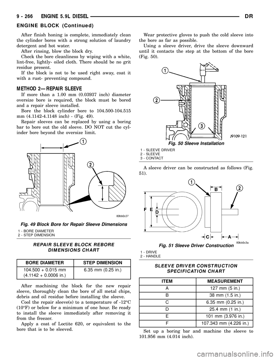
METHOD 2ÐREPAIR SLEEVE
If more than a 1.00 mm (0.03937 inch) diameter
oversize bore is required, the block must be bored
and a repair sleeve installed.
Bore the block cylinder bore to 104.500-104.515
mm (4.1142-4.1148 inch) - (Fig. 49).
Repair sleeves can be replaced by using a boring
bar to bore out the old sleeve. DO NOT cut the cyl-
inder bore beyond the oversize limit.
REPAIR SLEEVE BLOCK REBORE
DIMENSIONS CHART
BORE DIAMETER STEP DIMENSION
104.500 + 0.015 mm
(4.1142 + 0.0006 in.)6.35 mm (0.25 in.)
After machining the block for the new repair
sleeve, thoroughly clean the bore of all metal chips,
debris and oil residue before installing the sleeve.
Cool the repair sleeve(s) to a temperature of -12ÉC
(10ÉF) or below for a minimum of one hour. Be ready
to install the sleeve immediately after removing it
from the freezer.
Apply a coat of Loctite 620, or equivalent to the
bore that is to be sleeved.Wear protective gloves to push the cold sleeve into
the bore as far as possible.
Using a sleeve driver, drive the sleeve downward
until it contacts the step at the bottom of the bore
(Fig. 50).
A sleeve driver can be constructed as follows (Fig.
51).SLEEVE DRIVER CONSTRUCTION
SPECIFICATION CHART
ITEM MEASUREMENT
A 127 mm (5 in.)
B 38 mm (1.5 in.)
C 6.35 mm (0.25 in.)
D 25.4 mm (1 in.)
E 101 mm (3.976 in.)
F 107.343 mm (4.226 in.)
Set up a boring bar and machine the sleeve to
101.956 mm (4.014 inch).
Fig. 49 Block Bore for Repair Sleeve Dimensions
1 - BORE DIAMETER
2 - STEP DIMENSION
Fig. 50 Sleeve Installation
1 - SLEEVE DRIVER
2 - SLEEVE
3 - CONTACT
Fig. 51 Sleeve Driver Construction
1 - DRIVE
2 - HANDLE
9 - 266 ENGINE 5.9L DIESELDR
ENGINE BLOCK (Continued)
Page 1496 of 2627
If the crankshaft is within limits, replace the bear-
ing. If the crankshaft is out of limits, grind the
crankshaft to the next smaller size and use oversize
rod bearings.
CRANKSHAFT AND GEAR
DESCRIPTION
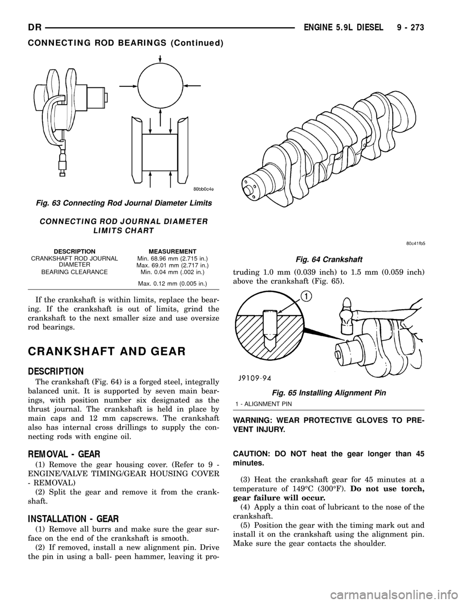
The crankshaft (Fig. 64) is a forged steel, integrally
balanced unit. It is supported by seven main bear-
ings, with position number six designated as the
thrust journal. The crankshaft is held in place by
main caps and 12 mm capscrews. The crankshaft
also has internal cross drillings to supply the con-
necting rods with engine oil.
REMOVAL - GEAR
(1) Remove the gear housing cover. (Refer to 9 -
ENGINE/VALVE TIMING/GEAR HOUSING COVER
- REMOVAL)
(2) Split the gear and remove it from the crank-
shaft.
INSTALLATION - GEAR
(1) Remove all burrs and make sure the gear sur-
face on the end of the crankshaft is smooth.
(2) If removed, install a new alignment pin. Drive
the pin in using a ball- peen hammer, leaving it pro-truding 1.0 mm (0.039 inch) to 1.5 mm (0.059 inch)
above the crankshaft (Fig. 65).
WARNING: WEAR PROTECTIVE GLOVES TO PRE-
VENT INJURY.
CAUTION: DO NOT heat the gear longer than 45
minutes.
(3) Heat the crankshaft gear for 45 minutes at a
temperature of 149ÉC (300ÉF).Do not use torch,
gear failure will occur.
(4) Apply a thin coat of lubricant to the nose of the
crankshaft.
(5) Position the gear with the timing mark out and
install it on the crankshaft using the alignment pin.
Make sure the gear contacts the shoulder.
Fig. 63 Connecting Rod Journal Diameter Limits
CONNECTING ROD JOURNAL DIAMETER
LIMITS CHART
DESCRIPTION MEASUREMENT
CRANKSHAFT ROD JOURNAL
DIAMETERMin. 68.96 mm (2.715 in.)
Max. 69.01 mm (2.717 in.)
BEARING CLEARANCE Min. 0.04 mm (.002 in.)
Max. 0.12 mm (0.005 in.)
Fig. 64 Crankshaft
Fig. 65 Installing Alignment Pin
1 - ALIGNMENT PIN
DRENGINE 5.9L DIESEL 9 - 273
CONNECTING ROD BEARINGS (Continued)
Page 1520 of 2627
(13) Install the cooling fan (Refer to 7 - COOLING/
ENGINE/RADIATOR FAN - INSTALLATION).
(14) Connect battery negative cables.
(15) Start engine and check for oil leaks.
INTAKE MANIFOLD
REMOVAL
(1) Disconnect the battery negative cables.
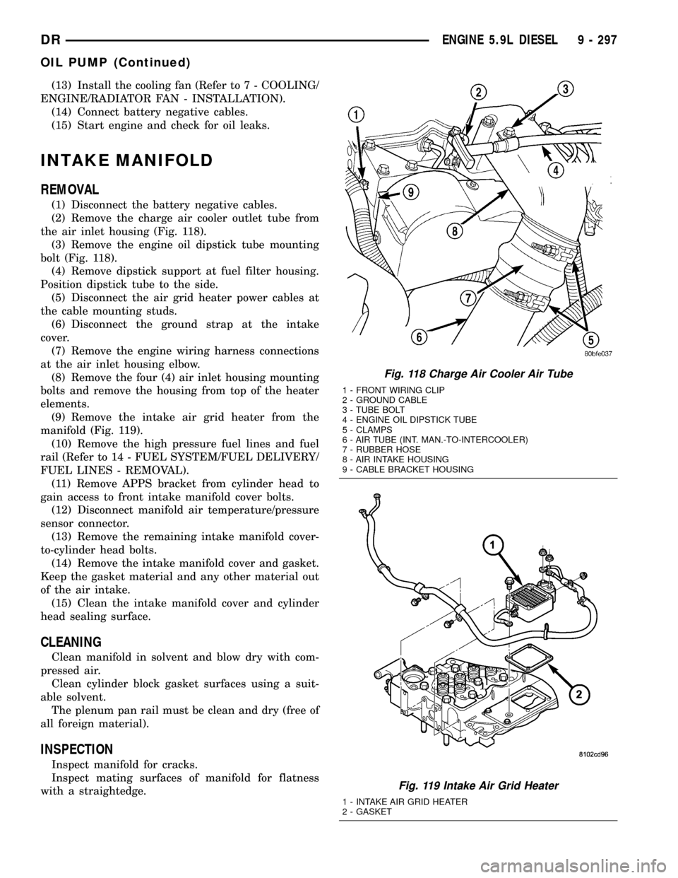
(2) Remove the charge air cooler outlet tube from
the air inlet housing (Fig. 118).
(3) Remove the engine oil dipstick tube mounting
bolt (Fig. 118).
(4) Remove dipstick support at fuel filter housing.
Position dipstick tube to the side.
(5) Disconnect the air grid heater power cables at
the cable mounting studs.
(6) Disconnect the ground strap at the intake
cover.
(7) Remove the engine wiring harness connections
at the air inlet housing elbow.
(8) Remove the four (4) air inlet housing mounting
bolts and remove the housing from top of the heater
elements.
(9) Remove the intake air grid heater from the
manifold (Fig. 119).
(10) Remove the high pressure fuel lines and fuel
rail (Refer to 14 - FUEL SYSTEM/FUEL DELIVERY/
FUEL LINES - REMOVAL).
(11) Remove APPS bracket from cylinder head to
gain access to front intake manifold cover bolts.
(12) Disconnect manifold air temperature/pressure
sensor connector.
(13) Remove the remaining intake manifold cover-
to-cylinder head bolts.
(14) Remove the intake manifold cover and gasket.
Keep the gasket material and any other material out
of the air intake.
(15) Clean the intake manifold cover and cylinder
head sealing surface.
CLEANING
Clean manifold in solvent and blow dry with com-
pressed air.
Clean cylinder block gasket surfaces using a suit-
able solvent.
The plenum pan rail must be clean and dry (free of
all foreign material).
INSPECTION
Inspect manifold for cracks.
Inspect mating surfaces of manifold for flatness
with a straightedge.
Fig. 118 Charge Air Cooler Air Tube
1 - FRONT WIRING CLIP
2 - GROUND CABLE
3 - TUBE BOLT
4 - ENGINE OIL DIPSTICK TUBE
5 - CLAMPS
6 - AIR TUBE (INT. MAN.-TO-INTERCOOLER)
7 - RUBBER HOSE
8 - AIR INTAKE HOUSING
9 - CABLE BRACKET HOUSING
Fig. 119 Intake Air Grid Heater
1 - INTAKE AIR GRID HEATER
2 - GASKET
DRENGINE 5.9L DIESEL 9 - 297
OIL PUMP (Continued)