1998 BMW 528i diagnostics
[x] Cancel search: diagnosticsPage 3 of 1002

Downloaded from www.Manualslib.com manuals search engine
YOU are now in Volume I
I
Foreword ................... .. ........................................................................\
.......... v
Index
........................ .. ................................................................ rear of manual
General, 001 General Warnings and Cautions 002 Vehicle Identification and VIN Decoder
Maintenance OiO 020 Maintenance
Engine
100 Engine-General 110 Engine Removal and Installation
113 Cylinder Head Removal and
Installation
116 Cyiinder Head and Valvetrain 117 Camshaft Timing Chain
119 Lubrication System
200 Transmission-General
2 Transmission 210 clutch 230 ManualTransmission
I20 Ignition System
121 Battery, Starter, Alternator
130 Fuel Injection
160 Fuel Tank and Fuel Pump 170 Radiator and Cooling System
180 Exhaust System
240 Automatic Transmission
250 Gearshift Linkage 260 Driveshaft
Suspension, 300 Suspension, Steering and 330 Rear Suspension
Brakes-General 331 Final Drive
Steering and No Front Suspension 340 Brakes
320 Steering and Wheel Alignment
400 Body-General
410 Fenders, Engine Hood 411 Doors
412 Trunk Lid, Tailgate
510 Exterior Trim, Bumpers 512 Door Windows
Equipment 513 Interior Trim
7
Equipment and 720 seat Belts
Accessories 721 Airbag System (SRS)
OBD On-Board Diagnostics
. ............ ..
515 Central Lociting and
Anti-Theft
520 Seats 540 Sunroof
.................................................................... Foreword .............................. .. v
Index ................... .. ................................................................ rear of manual
Electrical
6 system
600 Electrical System-General 620 Instruments
610 Electrical Comoonent Locations 630 Liohts
611 wipers and washers 612 Switches eati in^ and Air Conditioning
Radio
. ........... ........ .........................
Electrical Wiring Diagrams
Page 12 of 1002

Downloaded from www.Manualslib.com manuals search engine
01 0-2
General
This section is intended to help the do-it-yourselfer get start-
ed. Tips on workshop practices, basic tools, and a quick refer-
ence guide to emergencies can be found here.
WARNING-
Do not use this manual unless you are familiar with basic
automotive repair procedures and safe workshop
practices.
0 This manual illustrates the worl
and up-to-date information from the vehicle manufac-
turer or for proper training as an automotive technician.
Note that it is not possible to anticipate all of the ways
or conditions under which vehicles may be serviced or
to provide cautions as to all of the possible hazards that
may result.
MOW TO USE THIS MANUAL
WARNING -
Your common sense and goodjudgement are crucial to safe
and successful service
work. Read procedures through be-
fore starting them. Think about whether the condition of your
cac your level of mechanical skill, or pour level of reading
comprehension might result in or contribute in some way to
an occurrence that might cause you injury, damage your car;
or result in an unsafe repair. If you have doubts for these or
other reasons about your ability to perform safe repair work
on your car; have the work done at an authorized
BMW deal-
er or other qualified shop.
The manual is divided into ten sections:
0 GENERAL, MAINTENANCE
0 I ENGINE
2 TRANSMISSION
3 SUSPENSION, STEERING AND BRAKES
4 BODY
5 BODY EQUIPMENT
6 ELECTRICAL SYSTEM
7 EQUIPMENT AND ACCESSORIES
- ELE ELECTRICAL WIRING DIAGRAMS
OBD ON-BOARD DIAGNOSTICS
Page 29 of 1002

Downloaded from www.Manualslib.com manuals search engine
General
Cars with discharged or dead batteries can be jump-started
using the good battery from another car. See owner's manual
for proper instruction on jump starting. When jump-starling
the engine, always note the following warnings.
4 Lower car. With all wheels on ground, fully tighten nuts in a
WARNING-
* Battery acid (electrolyte) can cause severe burns, and will
damage the
cal; clothing, and you. If electrolyte is spilled,
wash the surface with large quantities of water.
M itgets into
eyes, flush them with water for several minutes and call a
doctor.
B4
5
43
2 BOOIFNG.
Batteries produce explosive and noxious gasses.
Keeps sparks and flames away. Do not smoke near
batteries.
Do notjump-start the engine
ifyou suspect that the bat-
tery is frozen. Trappedgas may explode. Allow the bat-
tery to thaw first.
Do not quick-charge the battery (for boost starting) for
longer than one minute, and do not exceed
16.5 volts
at the battery with the boosting cables attached. Wait at
least one minute before boosting the battery a second
time.
crisscross pattern.
Torque wheel nuts when installing wheel.
Check inflation pressure of spare tire.
Tightening torque
Wheel to wheel hub 120 Nm (89 ft-ib)
Jump starting
Indicator and warning lights
Many vehicle systems are self-monitored for faults while driv-
ing. Generally,
a red warning lamp that comes on during driv-
ing should be considered serious. If you cannot immediately
determine the seriousness of the warning light, stop the vehi-
cle in a safe place and turn the engine off as soon as possible.
Consult the owner's manual for additional information on the
warning lamp and the recommended action.
If the Malfunction Indicator Lamp (MIL)
(Check Engine or Ser-
vice Engine Soon warning light) comes on orflashes, it indi-
cates that an emissions-related fault has occurred. Faults
such as a bad oxygen sensor or a dead fuel injector can
cause the exhaust or evaporative emissions to exceed a
specified limit. When these limits are exceeded, the MIL will
be turned on. The engine can be safety driven with the light
on, although the emission systems should be
checked as
soon as possible. See OBD On-Board Diagnostics for
Page 51 of 1002

Downloaded from www.Manualslib.com manuals search engine
Maintenance
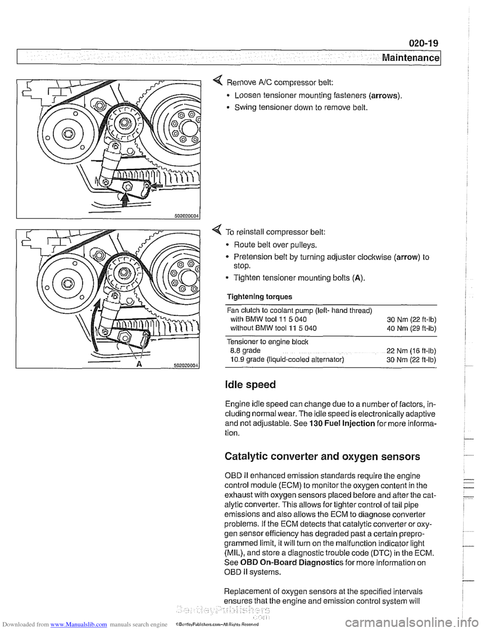
< Remove NC compressor belt:
Loosen tensioner mounting fasteners (arrows)
Swing tensioner down to remove belt.
4 To reinstall compressor belt:
Route belt over pulleys.
* Pretension belt by turning adjuster clockwise (arrow) to
stop.
- Tighten tensioner mounting bolts (A).
Tightening torques
Fan clutch to coolant pump (left- hand thread)
with BMW tool
11 5 040
30 Nm (22 ft-lb)
without BMW tool 11 5 040
40 Nm (29 ft-lb)
Tensioner to engine block
8.8 grade
22 Nm (16 ft-lb)
10.9 grade (Ilquid-cooled alternator) 30 Nm (22 ft-lb)
Idle speed
Engine idle speed can change due to a number of factors, in-
cluding normal wear. The idle speed is electronically adaptive
and not adjustable. See
130 Fuel Injection for more informa-
tion.
Catalytic converter and oxygen sensors
OBD II enhanced emission standards require the engine
control module (ECM) to monitor the oxygen content in the
exhaust with oxygen sensors placed before and after the cat-
alytic converter. This allows for tighter control of tail pipe
emissions and also allows the ECM to diagnose converter
problems. If the ECM detects that catalytic converter or oxy-
gen sensor efficiency has degraded past a certain
prepro-
grammed limit, it will turn on the malfunction indicator light
(MIL), and store a diagnostic trouble code (DTC) in the ECM.
See OBD On-Board Diagnostics for more information on
OBD
ll systems.
Replacement of oxygen sensors at the specified intervals
he engine and emission control system will
Page 70 of 1002

Downloaded from www.Manualslib.com manuals search engine
100-4
I Engine-General
The M62 90" V8 engine uses four valves per cylinder, double
overhead camshafts and light alloy cylinder head and cylin-
der
bloclc engine construction.
On 1997 and 1998 540i models, Bosch engine management
systems are utilized. Table a lists engine management sys-
tem applications.
4 For the 1999 model year, the M62 TU VANOS engine was in-
troduced to the 540i models. This engine is primarily a carry-
over from the earlier M62 engine, but contains many unique
identifying components and technology:
Variable camshaft timing (VANOS) for the intake valves.
Bosch ME 7.2 engine management system with electronic
throttle control. There is no accelerator cable connecting
the throttle pedal to the throttle housing in these cars.
Compact water-cooled generator (alternator).
E39 vehicles are equipped with sophisticated self-diagnostic
engine management systems. These systems monitor and
store diagnostic fault information. If the malfunction indicator
lamp (MIL) illuminates, the first diagnostic test should be to
connect a dedicated scan tool for BMW automobiles and in-
terrogate the fault memory.
If the malfunction indicator light (MIL) comes on orflashes, it
indicates that an emissions-related fault has occurred and
that fault information is stored in memory within the ECM.
4 The MIL in E39 cars displays one of these warning graphics
in the instrument cluster.
The diagnostic capabilities of these systems have the poten-
tial to save hours of diagnostic time and prevent incorrect
5 placement. See OBD On-Board Diagnostics.
Page 75 of 1002

Downloaded from www.Manualslib.com manuals search engine
110-3
Engine Removal and lnstallationl
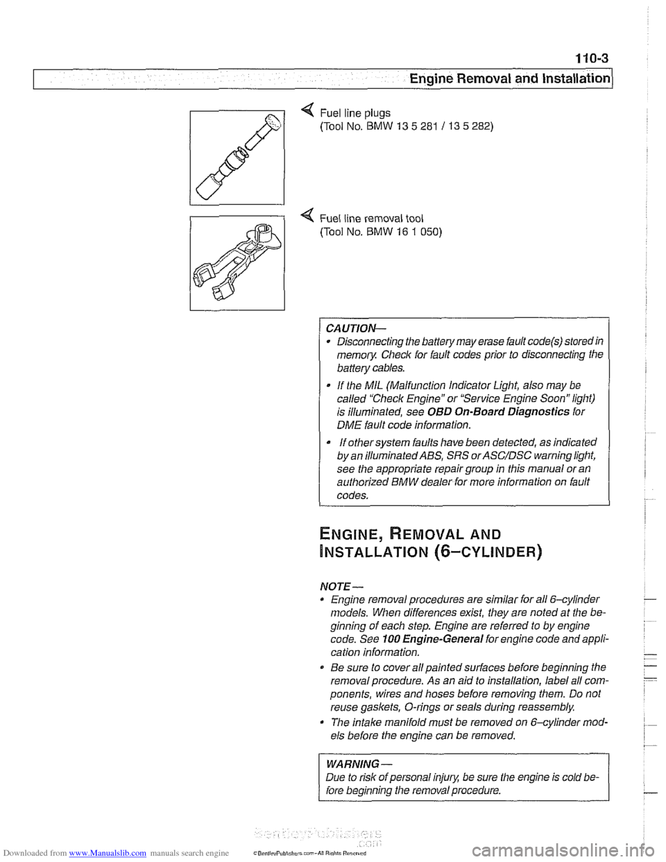
Q Fuel line plugs
(Tool No.
BMW 13 5 281 / 13 5 282)
4 Fuel line removal tool
(Tool No.
BMW 16 1 050)
CAUTION-
Disconnecting the battery may erase fault code@) storedin
memoiy Check for fault codes prior to disconnecting the
battery cables.
If the MIL (Malfunction Indicator Light, also may be
called "Check Engine" or "Service Engine Soon" light)
is illuminated, see
OBD On-Board Diagnostics for
DME fault code information.
It orhersysrem faults have been detected, as indicated I
by an ~llum~nated ABS, SRS orASC/DSC ~arning light,
see the appropriate repair group in this manual or an
authorized BMW dealer for more information on fault
codes.
NOTE- Engine removal procedures are similar for all 6-cylinder
models. When differences
exist, they are noted at the be-
ginning of each step. Engine are referred to by engine
code. See
100 Engine-General for engine code and appli-
cation information.
@ Be sure to cover all painted surfaces before beginning the
removal procedure. As an aid to installation, label all com-
ponents, wires and hoses before removing them. Do not
reuse
gaskets, O-rings or seals during reassembly.
The
intake manifold must be removed on &cylinder mod-
els before the engine can be removed.
WARNING-
Due to risk of personal injury, be sure the engine is cold be-
fore beginning the removal procedure.
Page 99 of 1002

Downloaded from www.Manualslib.com manuals search engine
113-5
Cylinder Head Removal and Installation I
< Fuel line plugs
(Tool No.
BMW 13 5 281113 5 282)
4 Fuel line removal tool for quick-disconnect fittings
(Tool No.
BMW 16 1 050)
< Tensioning bracket (V-8)
(Tool No. BMW 11 7 380)
Compressed air fitting for testing VANOS operation
((Tool No.
BMW 11 3 450)
< Upper timing cover installation tool set, V-8
(Tool No. BMW 11 1 41 0)
Cylinder compression, checking
A compression gauge is needed to make a compression test.
For accurate test, the battery and starter must be capable of
cranking the engine at least
300 rpm, and the engine should
be at normal operating temperature.
NOTE-
Performing a compression test may cause a fault to set in the
ECM and may illuminate the Malfunction
Indicator Light
(MIL). The light can only be turned out using either
BMW
special service scan tools or an equivalent aftermarket scan
tool. Disconnecting the battery will not erase the fault memo-
ry or turn out the light. See OBD On-Board Diagnostics.
Page 271 of 1002

Downloaded from www.Manualslib.com manuals search engine
Camshaft Timing Chain
1 VANOS I 4 When engine is started, camshafts are in deactivated
camshaft
retarded Engine I i oil supply
position:
. lntalte camshaft is held in RETARDED position by oil
pressure.
Exhaust camshaft is held in ADVANCED position by
preload spring and oil pressure.
VANOS
Piston out
ECM Piston in Within 2
- 5
seconds (50 engine revolutions), the ECM begins
monitoring and controlling camshaft positions.
The Double VANOS system allows full variability of camshaft
timing up to the limits of the system. When the ECM detects
that the camshafts are in optimum position, the solenoids are
modulated at approximately 100
- 220 Hz to maintain oil pres-
sure on both sides of the actuator pistons to maintain timing.
In models with DME
MS 43.0 (model year2001 and newer),
the engine control module (ECM) detects camshaft position
before the engine starts, thereby adjusting camshaft timing
immediately upon start-up.
NOTE-
. VANOS system troubleshooting and diagnostics is best
accomplished using a scan tool.
. Diagnostic Trouble Codes (DTCs) pertaining to the
VANOS system are listed
in the following table. See also
OED On-Board Diagnostics.
Elevated oil temperatures can cause VANOS to deactivate.
Oil that is too thick (high viscosity) may cause
a DTC to be
set
in the ECM. If VANOS is deactivated (limp-home
mode), there will be a noticeable loss of power.
VANOS fault codes
BMW code P-code Fault description
19
PI529 VANOS solenoid valve activation,
exhaust
21
PI525 VANOS solenoid valve activation,
intake
103
PI519 VANOS faulty reference value
intake
104
PI520 VANOS faulty reference value
exhaust
105
PI522 VANOS stuck (Bank I) intake
106
PI523 VANOS stuck (Bank 2) exhaust