Page 57 of 75
37-52
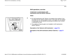
Shift mechanism (without Tiptronic),
disassembling and assembling
The Tiptronic shift mechanism is described on
page 37
-6 .
Note:
For all further work on the shift mechanism, the
front center console must be removed.
Repair Manual, Body Interior, Repair Group 68;
storage compartments/covers; front center console, removing and installing
1 -
Selector lever handle
Press casing item 2 downward, pull out
button at handle up to stop and pull off
handle upward.
2 -
Sleeve Engages in the selector lever handle
Pa
ge 57 of 75 Selector lever mechanism, servicin
g
11/20/2002 htt
p://127.0.0.1:8080/audi/servlet/Dis
play?action=Goto&t
yp
e=re
pair&id=AUDI.B5.AT01.37.1
Page 58 of 75
37-53
3 -
Cover
With gear display and display for shift lock
solenoid To remove, disengage retaining tabs for
shift mechanism housing Remove upward together with item 4 and
5 .
4 -
Light track With wiring harness and LEDs for base
illumination Wire routing Fig. 4
, page 37
-61
5 -
Guide
With masking panel and mirror for
individual gear display Mechanism can be loosened from the
cover by disengaging the four retaining
tabs at interior.
Pa
ge 58 of 75 Selector lever mechanism, servicin
g
11/20/2002 htt
p://127.0.0.1:8080/audi/servlet/Dis
play?action=Goto&t
yp
e=re
pair&id=AUDI.B5.AT01.37.1
Page 59 of 75
37-54
6 -
Retaining spring
For locking cableClip into shift mechanism housing page 37
-47
7 -
Locking cable
Must not be kinkedRemoving page 37
-47
Installing and adjusting page 37
-69
8 -
Locking washer
For pin item 9
9 -
Pin For lever item 10
Pa
ge 59 of 75 Selector lever mechanism, servicin
g
11/20/2002 htt
p://127.0.0.1:8080/audi/servlet/Dis
play?action=Goto&t
yp
e=re
pair&id=AUDI.B5.AT01.37.1
Page 60 of 75
37-55
Repair Manual, 5 Spd. Automatic Transmission
01V On Board Diagnostic (OBD), Repair Group 01; On Board Diagnostic (OBD); Read measuring value block
10 -
Locking cable lever
11 -
Shift lock solenoid -N110-
Removing and installing Fig. 3
, page
37
-61
Unclip connector from wiring harness (at
center console) item , page 37
-61
Can be checked via electrical test and read
measuring value block
12 -
Spring bracket
Insert both ends into selector lever
13 -
Locking segment Insert into selector lever together with
spring bracket
Pa
ge 60 of 75 Selector lever mechanism, servicin
g
11/20/2002 htt
p://127.0.0.1:8080/audi/servlet/Dis
play?action=Goto&t
yp
e=re
pair&id=AUDI.B5.AT01.37.1
Page 61 of 75
37-56
14 -
Cover
For shift mechanism housingRemoving and installing Fig. 1
, page
37
-59
15 -
Locking clamp
For selector lever cable to selector lever
16 -
Locking plate For selector lever cable to shift mechanism
housing Fig. 2
, page 37
-60
item E
17 -
Clip
For selector lever cable to transmission
shift lever
18 -
Hex-bolt, 23 Nm
19 -
Hex-bolt, 23 Nm
20 -
Pivot For selector lever cable at transmission
Pa
ge 61 of 75 Selector lever mechanism, servicin
g
11/20/2002 htt
p://127.0.0.1:8080/audi/servlet/Dis
play?action=Goto&t
yp
e=re
pair&id=AUDI.B5.AT01.37.1
Page 62 of 75
37-57
Note:
For all further work, shift mechanism must be
removed completely from the vehicle. 21 -
Selector lever cable
Removing and installing page 37
-62
Adjusting page 37
-45
22 -
Nut - 9 Nm
4x
23 -
Rubber housing Must only be separated from shift
mechanism housing item 25 if damaged or
to remove selector lever. Installation and installation position Fig. 2 , page 37
-60
Pa
ge 62 of 75 Selector lever mechanism, servicin
g
11/20/2002 htt
p://127.0.0.1:8080/audi/servlet/Dis
play?action=Goto&t
yp
e=re
pair&id=AUDI.B5.AT01.37.1
Page 63 of 75
37-58
24 -
Pivot pin
Removing: carefully press out using
screwdriver
25 -
Shift mechanism housing Removing and installing Fig. 2
, page
37
-60
26 -
Selector lever
27 -
Pull-lever
Insert into selector lever together with
spring item 28
28 -
Spring For pull-lever
29 -
Ignition/Starter Switch
Pa
ge 63 of 75 Selector lever mechanism, servicin
g
11/20/2002 htt
p://127.0.0.1:8080/audi/servlet/Dis
play?action=Goto&t
yp
e=re
pair&id=AUDI.B5.AT01.37.1
Page 64 of 75
37-59
Note:
Cover can be removed and installed from below with the shift mechanism
installed.
Removing
Installing Fig. 1 Cover, removing and installing
- Press in direction of (arrow I) and disengage snap-lock to shift
mechanism housing.
- Guide cover into groove -D- and then engage snap-lock.
- Check cover for proper seating and seal.
Pa
ge 64 of 75 Selector lever mechanism, servicin
g
11/20/2002 htt
p://127.0.0.1:8080/audi/servlet/Dis
play?action=Goto&t
yp
e=re
pair&id=AUDI.B5.AT01.37.1


,
disassembling and assembling
The Tiptronic shift mechanism is described on
page 37
-6 .
Note:
For all further work on the shift mechanism, the")


, Repair Group 01; On Board Diagnostic (OBD); Read measuring value block
10 -
Locking cable lever
11 -
Shi")


