Page 9 of 75
37-7
All-wheel-drive vehicles
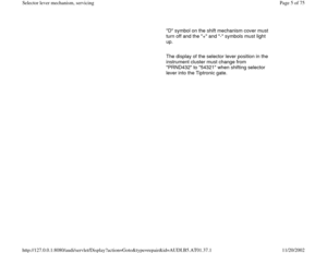
Continuation for all vehicles - Remove heat shield -A- above driveshaft.
- Remove heat shield -2- for driveshaft from cover for Torsen differential
(arrows).
- Unbolt driveshaft from transmission and hang or support.
- Loosen boot of selector lever cable from shift mechanism cover and
slide back.
- Remove bolts (arrows) and remove shift mechanism cover.
Pa
ge 9 of 75 Selector lever mechanism, servicin
g
11/20/2002 htt
p://127.0.0.1:8080/audi/servlet/Dis
play?action=Goto&t
yp
e=re
pair&id=AUDI.B5.AT01.37.1
Page 10 of 75
37-8
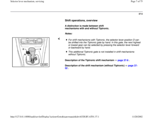
from top:
from below: - Press ends of locking clip -B- together and remove.
- Remove securing plate -A- for selector lever cable at shift mechanism
downward.
- Remove selector lever cable from selector lever.
- Unclip locking cable from securing spring at shift mechanism housing,
slightly lift up securing spring to do so.
- Remove nuts (4 pieces).
- Remove shift mechanism housing downward.
- Pull selector lever cable out of shift mechanism at the same time, and
do not bend.
Pa
ge 10 of 75 Selector lever mechanism, servicin
g
11/20/2002 htt
p://127.0.0.1:8080/audi/servlet/Dis
play?action=Goto&t
yp
e=re
pair&id=AUDI.B5.AT01.37.1
Page 11 of 75
37-9
Installing
- Installation is the reverse order of removal.
In addition, the following test steps must be
performed and observed.
Selector lever and lever/shift rod in position
"P" (park lock must engage).
- Raise vehicle.
- Guide selector lever cable into shift
mechanism.
- Do not bend selector lever cable.
- Mount shift mechanism on chassis.
- Tighten nuts (4 pieces) to 10 Nm from top.
- Secure boot of selector lever cable to shift
mechanism cover.
- Installing and adjusting locking cable page 37
-49
.
Pa
ge 11 of 75 Selector lever mechanism, servicin
g
11/20/2002 htt
p://127.0.0.1:8080/audi/servlet/Dis
play?action=Goto&t
yp
e=re
pair&id=AUDI.B5.AT01.37.1
Page 12 of 75
- Connect selector lever cable to selector lever.
Installation position:
Angled end of securing plate points toward the end of the selector lever
cable. - Install securing plate -A- for selector lever cable to shift mechanism.
- Press ends of locking clip -B- together and slide onto the end of the
selector lever cable.
Pa
ge 12 of 75 Selector lever mechanism, servicin
g
11/20/2002 htt
p://127.0.0.1:8080/audi/servlet/Dis
play?action=Goto&t
yp
e=re
pair&id=AUDI.B5.AT01.37.1
Page 13 of 75
37-10
- Attach cover.
All-wheel-drive vehicles
Continuation for all vehicles
Repair Manual, Engine Mechanical, Repair Group 26; removing and
installing exhaust system. - Tighten nuts (arrows, 4 pieces) to 10 Nm.
- Check adjustment of selector lever cable and adjust if necessary
page 37
-45
.
- Ignition key removal lock, checking page 37
-1 .
- Bolt driveshaft to transmission flange page 39
-79
, Driveshaft,
removing and installing.
- Install heat shield.
- Connecting front exhaust pipe to rear exhaust system.- Installing shift mechanism cover page 37
-24
.
- Selector lever handle, installing page 37
-22
.
- Connect battery Ground (GND) strap.
- For vehicles equipped with coded anti-theft radio, activate code.
- Check shift mechanism page 37
-2 .
Pa
ge 13 of 75 Selector lever mechanism, servicin
g
11/20/2002 htt
p://127.0.0.1:8080/audi/servlet/Dis
play?action=Goto&t
yp
e=re
pair&id=AUDI.B5.AT01.37.1
Page 14 of 75
37-11
Tightening torques:
Components
Tightening
torques
Selector lever cable to mounting
bracket 12 Nm
Mounting bracket to
transmission (2 x M8) 23 Nm
Heat shield/selector lever cable
to transmission, M6 9 Nm
Heat shield/selector lever cable
to transmission, M8 23 Nm
Selector lever mechanism to
chassis M6 8 Nm
Pa
ge 14 of 75 Selector lever mechanism, servicin
g
11/20/2002 htt
p://127.0.0.1:8080/audi/servlet/Dis
play?action=Goto&t
yp
e=re
pair&id=AUDI.B5.AT01.37.1
Page 15 of 75
37-12
Tiptronic shift mechanism, assembly
overview
Assembly sequence page 37
-32
Lubricate bearing areas and slide surfaces with
polycarbamide grease Part No. G 052 142 A2.
1 -
Selector lever handle
Removing and installing page 37
-22
2 -
Sleeve
Engages in the selector lever handle
3 -
Cover Removing and installing page 37
-24
Disassembling and assembling page 37
-
27
Pa
ge 15 of 75 Selector lever mechanism, servicin
g
11/20/2002 htt
p://127.0.0.1:8080/audi/servlet/Dis
play?action=Goto&t
yp
e=re
pair&id=AUDI.B5.AT01.37.1
Page 16 of 75
37-13
4 -
Bearing bushing
Use securing device - 5 - or secure 9 - in
shift mechanism - 17 Removing and installing page 37
-32
5 -
Locking clip (thin, with tensioning spring)
Secures bushing 17 - in shift mechanism- 4
- Installation position:Angled ends point to
the inner shift mechanism housing
6 -
Selector lever With pull-lever, compression spring, link
and Tiptronic-spring system Removing and installing Page 37
-22
onward
Disassembling and assembling page 37
-
36
Pa
ge 16 of 75 Selector lever mechanism, servicin
g
11/20/2002 htt
p://127.0.0.1:8080/audi/servlet/Dis
play?action=Goto&t
yp
e=re
pair&id=AUDI.B5.AT01.37.1


 23 Nm
Heat shield/selector")


Secures bushin")