Page 25 of 43
39-48
Checking measurement
Checking dimension "r"
- Install pinion shaft together with measured
shims S3 and S4 and turn 5 rotations in both
directions.
Note:
After removing universal mandrel, and with VW385/30 master gauge or
VW385/15 extension pin in place, check dial indicator again to see if it
indicates 0 with 2 mm preload. If not, correct adjustments. - Install universal mandrel Page 39
-43
, Determining dimension "e";
and perform check measurement.
- Read dial indicator counterclockwise (red scale).
If shims have been determined correctly, deviation "r" (as marked
on outer circumference of ring gear) should be indicated on dial
within a tolerance of 0.04 mm.
Pa
ge 25 of 43 Pinion shaft and rin
g gear, ad
justin
g
11/19/2002 htt
p://127.0.0.1:8080/audi/servlet/Dis
play?action=Goto&t
yp
e=re
pair&id=AUDI.B5.TM01.39.5
Page 26 of 43
39-49
Re-determining "S4" after replacing
transmission cover
Special tools and equipment
VW387 dial gauge holder
VW792/1 assembly tool
Dial indicator
Dial indicator extension
Depth gauge with minimum 5/100 mm
precision
- Clean housing mating surfaces.
Example: - Measure difference in depth "a" on old and new transmission cover.
Depth -a- (old transmission cover) 257.40 mm
Depth -a- (new transmission cover) 257.55 mm
= Difference 0.15 mm
Pa
ge 26 of 43 Pinion shaft and rin
g gear, ad
justin
g
11/19/2002 htt
p://127.0.0.1:8080/audi/servlet/Dis
play?action=Goto&t
yp
e=re
pair&id=AUDI.B5.TM01.39.5
Page 27 of 43
39-50
- Install thicker shim "S4" if new transmission
cover is deeper.
- Install thinner shim "S4" when the old
transmission cover is deeper.
Example:
Previous shim "S4" 0.95 mm
+ Difference 0.15 mm
= New shim "S4" 1.10 mm
Available shims Page 39
-47
, table
- Install tapered roller bearing outer race with
shim "S4" into transmission cover Fig. 8
,
Page 35
-32
.
- Install fully assembled pinion shaft into
transmission housing.
- Install transmission cover and tighten to 22 Nm
(16 ft lb).
Pa
ge 27 of 43 Pinion shaft and rin
g gear, ad
justin
g
11/19/2002 htt
p://127.0.0.1:8080/audi/servlet/Dis
play?action=Goto&t
yp
e=re
pair&id=AUDI.B5.TM01.39.5
Page 28 of 43
39-51
Preload for tapered roller bearing for pinion
shaft, checking
- Turn pinion shaft 5 rotations in each direction to
seat the tapered roller bearing.
Note:
The pinion shaft can be turned by simultaneously
turning both drive flanges.
- Install measuring tools and secure to transmission housing with bolt
(arrow).
- Attach dial indicator (3 mm measuring range) to center of transmission
cover and set to 0 with 2 mm preload.
- Loosen transmission cover bolts and turn pinion shaft.
If correct shims have been selected, the dial indicator will now indicate
the following value: 0.05-0.15 mm.
- Remove measuring tools.
- Coat sealing surfaces with thin layer of sealant AMV 188 001 02.
- Tighten transmission cover bolts to 22 Nm (16 ft lb).
Pa
ge 28 of 43 Pinion shaft and rin
g gear, ad
justin
g
11/19/2002 htt
p://127.0.0.1:8080/audi/servlet/Dis
play?action=Goto&t
yp
e=re
pair&id=AUDI.B5.TM01.39.5
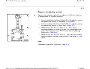
Page 29 of 43
39-52
Ring gear, adjusting
Adjusting differential
For a list of the repairs which will require the ring
gear to be adjusted Page 39
-33
, List of
adjustments
Special tools and equipment
VW382/10 dial indicator extension
VW385/17 magnetic plate
VW387 dial gauge holder
VW388 measuring lever
VW402 thrust plate
VW408A punch
VW472/1 pressure piece
VW521 adjustment tool
3177 clamp
Pa
ge 29 of 43 Pinion shaft and rin
g gear, ad
justin
g
11/19/2002 htt
p://127.0.0.1:8080/audi/servlet/Dis
play?action=Goto&t
yp
e=re
pair&id=AUDI.B5.TM01.39.5
Page 30 of 43
Torque gauge 0-600 Ncm
Dial indicator
Dial indicator extension 30 mm
Pa
ge 30 of 43 Pinion shaft and rin
g gear, ad
justin
g
11/19/2002 htt
p://127.0.0.1:8080/audi/servlet/Dis
play?action=Goto&t
yp
e=re
pair&id=AUDI.B5.TM01.39.5
Page 31 of 43
39-53
Determining total shim thickness Stotal for
shims S1 + S2
(Adjust preload of tapered roller bearing for
differential)
Pinion shaft removed
Note:
If only the differential tapered roller bearings are
to be replaced, remove ring gear from differential
housing. The pinion shaft does not have to be
removed.
- Remove seals and outer races from both
tapered roller bearings for differential.
- Remove shims Page 39
-15
.
Note:
A shim S2 with a thickness of 1.20 mm is installed for initial measurement.
It is referred to in the following text as S2*. After determining backlash, S2*
is replaced with the appropriate shim S2. - Drive in tapered roller bearing outer race together with shim S2 into
transmission housing Fig. 3, Page 39
-23
. Use shim "S2*" with
1.20 mm thickness for measurement purposes (2 shims with 0.60 mm).
Pa
ge 31 of 43 Pinion shaft and rin
g gear, ad
justin
g
11/19/2002 htt
p://127.0.0.1:8080/audi/servlet/Dis
play?action=Goto&t
yp
e=re
pair&id=AUDI.B5.TM01.39.5
Page 32 of 43
39-54
- Press in tapered roller bearing outer race into differential cover without
shim S1 Fig. 9
, Page 39
-26
.
- Install differential into transmission housing without Vehicle Speed
Sensor (VSS) -G22- gear drive. Ring gear is located on left side in front
of final drive cover.
- Install cover for differential and tighten four bolts to 25 Nm (18 ft lb).
- Position transmission so that cover for differential faces upward.
- Turn differential 5 rotations in each direction to seat tapered roller
bearing.
Note:
Tip of dial indicator must be positioned on the center of the differential. - Assemble measuring equipment, use 30 mm dial indicator extension.
- Set dial indicator (3 mm measuring range) -A- to 0 with 2mm preload.
Pa
ge 32 of 43 Pinion shaft and rin
g gear, ad
justin
g
11/19/2002 htt
p://127.0.0.1:8080/audi/servlet/Dis
play?action=Goto&t
yp
e=re
pair&id=AUDI.B5.TM01.39.5


Pinion shaft removed
Note:
If only th")
