Page 79 of 1680

Gylinder Head
Removal (cont'dl
Remove the fuel return hose and positive crankcase
ventilation (PCV) hose.
Remove the brake booster vacuum hose, water
bypass hose and vacuum hose.
ltosE
VACUUM HOSE
6-18
10.
9.
11.
Remove the throttle cable,
Remove the throttle control cable (automatic trans-
mission only).
NOTE:
. Take care not to bend the cable when removing
it. Always replace any kinked cable with a new
one.
. Adjust the throttle cable and throttle control
cable when installing (s€e section 11 and 14).
THROTTLE CONTROLCABLE
ADJUSTING NUT
Remove the engine wire harness connectors and
wire harness clamps f.om the cylinder head and the
intake manifold.
Four fuel injector connectors
Intake air temperature (lATl sensor connector
Engine coolant temperature {ECT) sensor con,
nector
TDC/CKP/CYP sensor connector
lgnition coil connector
ECT gauge sending unit connector
Throttle position (TP) sensor connector
Manifold absolute pressure (MAP) sensor con-
necto r
ldle air control (lAC) valve connector
EVAP purge control solenoid valve connector
Crankshaft speed fluctuation (CKF) sensor con-
nector
a
a
a
a
a
a
a
a
ADJUSTING
Page 158 of 1680

11
Bore Honing
l/easure cylinder bores as shown on page 7-14.lf the block is to be reused, hone the cylinders andremeasure the bores.
Hone cylinder bores with honing oil and a fine (400
grat) stone in a 60 degree cross-hatch pattern.
NOTE:
. Use only a rigid hone with 400 grit or finer stonesuch as Sunnen, Ammco, or equivalent.a Do not use stones that are worn or oroKen.
When honing is complete, thoroughly clean thecylinder block of all melal particles. Wash the cylin-der bores with hot soapy water, then dry and oilimmediately to prevent rusting.
NOTE: Never use solvent, it wili only redistribute
the grit on the cylinder walls.
lf scoring or scratches are still present in cylinderbores after honing to the service limit, rebore theengine block.
NOTE: Some light vertical scoring and scratching isacceptable if it is not deep enough to catch your fin-gernail and does not run the full length ofthe bore.
NOTE:
. After honing, clean the cylinder thoroughly withsoapy water.o Only scored or scratched cylinder bores must behoned.
4.
7-15
Page 194 of 1680
Cooling
lllustrated Index ........
Radiator
Replacement ..............
Engine Coolant Refilling and
Bleeding
Cap Testing
Pressure Testing
Thermostat
Replacement ..............
Testing
Water Pump
lllustrated Index .........
Inspection
Replacement ...............
10-2
10-5
10-6
10-8
10-8
10-9
10-9
10-10
10-11
10-11
Page 195 of 1680

lllustrated Index
!$!!@ sv"t"m is under high plessure when the
engine is hot, To avoid dangei of releasing scalding
engine coolant, remove the cap only when engine is cool.
Total Cooling System Capacity {lncluding heater and
leservoir)
Bl8Bl engine:
MIT: 6.4 l. {6.8 US qt, 5.6 lmp qt)
Ant 6.7 t (7.1 US qt,5.9 lmp qt)
B18C1, 818C5 engines:
Mfi:6.7 t (7.1 US qt, 5.9 lmp qt)
CAUTION: lf any engine cgolant spills on painted por-
tions of the body, rinse it off immediately.
NOTE:
a Check all cooling system hoses for damage, leaks or
deterioration and replace il necessary.
a Check all hose clamps and retighten if necessary.
a Use new O-rings when reassembling.
RADIATOREngine coolant refilling and bleeding,page 10-6Leak test, page 10 8Inspecl soldered joints andseams for leaks,RAOIATOR CAPPressure test, page 10-8
UPPERRADIA
rl
]
CONDENSERFAN SHROUD{s€o section 22)
6 x 1.0 mm7 N.m {0.7 kgl.m, 5 lbf'ftl
5x0.8mm4.4 N.m (0.45 kgl.m,3.3 tbt.ft)
Blow out dirt from betweencore fins with compressed air.lf insects, etc., are cloggingradiator, wash them o{f withlow paessure water,
TOR HOSE
\*
\sffi((
@)
ATF COOLERHOSES181881 €ngin
S!g
R
U
COOLANTRESERVOIR
M/T: Manual lransmissionA/T: Automatic transmissionATF: Automatic t.ansmission fluid
FAN SHROUD
10-2
Page 199 of 1680
Radiator
Engine Coolant Refilling and Bleeding
CAUTION: When pouring engine coolant, be sure to shut
th6 relay box lid and not to l€t coolant spill on th6 el€c-
trical parts or the paint. lf any coolant spills, rinse it off
immediately.
1. Slide the heater temDerature control lever to maxi-
mum heat.
Make sure the engine and radiator are cool to the
touch.
2. Remove the radiator cap.
3. Loosen the drain plug, and drain the coolant.
4. Remove the drain bolt from the cvlinder block.
ji
Ii'
l:ll
ENGINE DRAIN EOLT78 N.m {8.0 kgt'm,54 lbt.ft)Apply liquid gasket tobolt thread when installing.WASHERReplace.
10-6
5. Apply liquid gasket to the drain bolt threads, then
reinstall the bolt with a new washer and tighten it
securely.
6. Tighten the radiator drain plug securely.
7. Remove, drain and reinstall the reservoir. Fillthe tank
halfway to the MAX mark with water, then up to
MAX mark with antifreeze.
COOLANTRESERVOIR
I
I
I
Page 200 of 1680

8.Mix the recommended antifreeze with an equal
amount of water in a clean container.
NOTE:
a Use only genuine Honda antifreeze/coolant.
a For best corrosion protection, the coolant concen-
tration must be maintained year-round at 500,6
minimum. Coolant concentrations less than 507o
may not provide sufficient protection against cor,
rosion or freezing.
a Coolant concentrations greater than 60% will im-
pair cooling efliciency and are not recommended.
CAUTION:
a Do not mix different brands of anti-lrcezel
coolants.
a Do not use additional rust inhibitots or anti-tustproducts; they may not be compatible with the
coolant.
Engine Coolant Refill Capacity [including reservoir
{0.6 { (0.6 US qt, 0.5 lmp qr)ll:
81881 engine:
Ml7:1-1t {/t.6 US qt. 3.9 lmp qtl
818B1, 818C1 engin€s:
AlTt 1.7 | 15.0 US qt, 4.1 lmp qt)
818C1, B18C5 engines:
MlTt 1.7 t 15.0 US $, 4.1 lmp qtl
FILLER NECK
9.Pour coolant into the radiator up to the base of the
tiller neck.
10. Startthe engine and let jt run until itwarmsup(the
radiator fan comes on at least twice).
1 1 . Turn olf the engine. Check the level in the radiator,
add coolant if needed.
'12. Put the radiator cap on tightly, then run the engine
again and check for leaks.
10-7
Page 202 of 1680
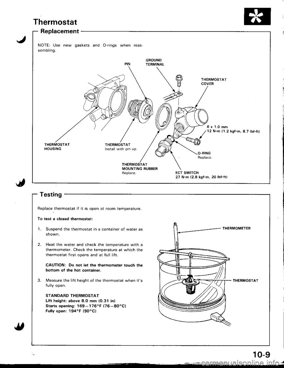
Thermostat
Replacement
NOTE: Use new gaskets and O-rings when reas'
sembling.
GROUNDTERMINAL
6 x 1.0 mm12 N.m {1.2 kgt.m,8.7 lbf.ft)
THERMOSTATInstall with pin up.O RINGReplace
ECT SWITCH27 N.m {2.8 kgf.m, 20 lbf.ftl
J
1.
Replace _thermostat if it as open at room temperature.
To test a closed thermostat:
Suspend the thermostat in a container of water as
shown.
Heat the water and check the temperature with a
thermometer. Check the temperature at which the
thermostat lirst opens and at full litt.
CAUTION: Do not let the ihermometer touch the
bottom of the hot container.
Measure the lilt height of the thermostat when it's
fully open.
STANDARD THERMOSTAT
Lift height: above 8.0 mm (O.31 inr
Stalts opening: 169- 1760 F (76-8OoC)
Fully open: 194o F l9OoCl
THERMOMETER
THERMOSTAT
2.
3.
10-g
. )
Page 203 of 1680
Water Pump
NOTE:
a Use new O-rings and new spgcial bolts when reassembling.
a Use liquid gasket, Part No. O8718 0001.
R;lll$ 818c1. 818c5 ensines:
ECT GAUGE SENDING UNITI N.m 10.9 kg{'m, 7 lbf'ftlApply liquid gasket
to the threads.
lllustrated lndex
6 x 1.0 mm11 N.m (1 .1 kgt.m.8.0 rbf.frt
ECT GAUGESENDING UNIT
818B1 engine:
OUTLET
ECT SWITCH27 N.m {2.8 kgf.m,20 lbf.fr)
ECT SENSOR
ENGINE COOLANTTEMPERATT,IRE IECTI SENSOR18 N'm (1.8 kgt.m, 13lbl'ft)
6 x 1.O mm11 N.m {1.1 kgI.m, 8.0 lbf.ft}
OUTLETCOVER
WATER PUMPInspecl|on,page 10-11
KNOCK SENSOR ADotv trouid oasket31 N.m 13.2 kgt.m, to ."t,nq .uif""".23 lbl.ftl
{818C1. 818C5 engines)
\,
O,RINGReplace.',O-RINGReplace.
6x1.0mm'12 N.m 11.2 kgt.m,8.7 lbI.fr)
THERMOSTAT HOUSINGASSEMBLY
O-RINGSReplace.
6 x 1.0 mm12 N.m (1.2 kgf.m, 8.7 lbI'ft)
COVER
10-10