Page 734 of 1680
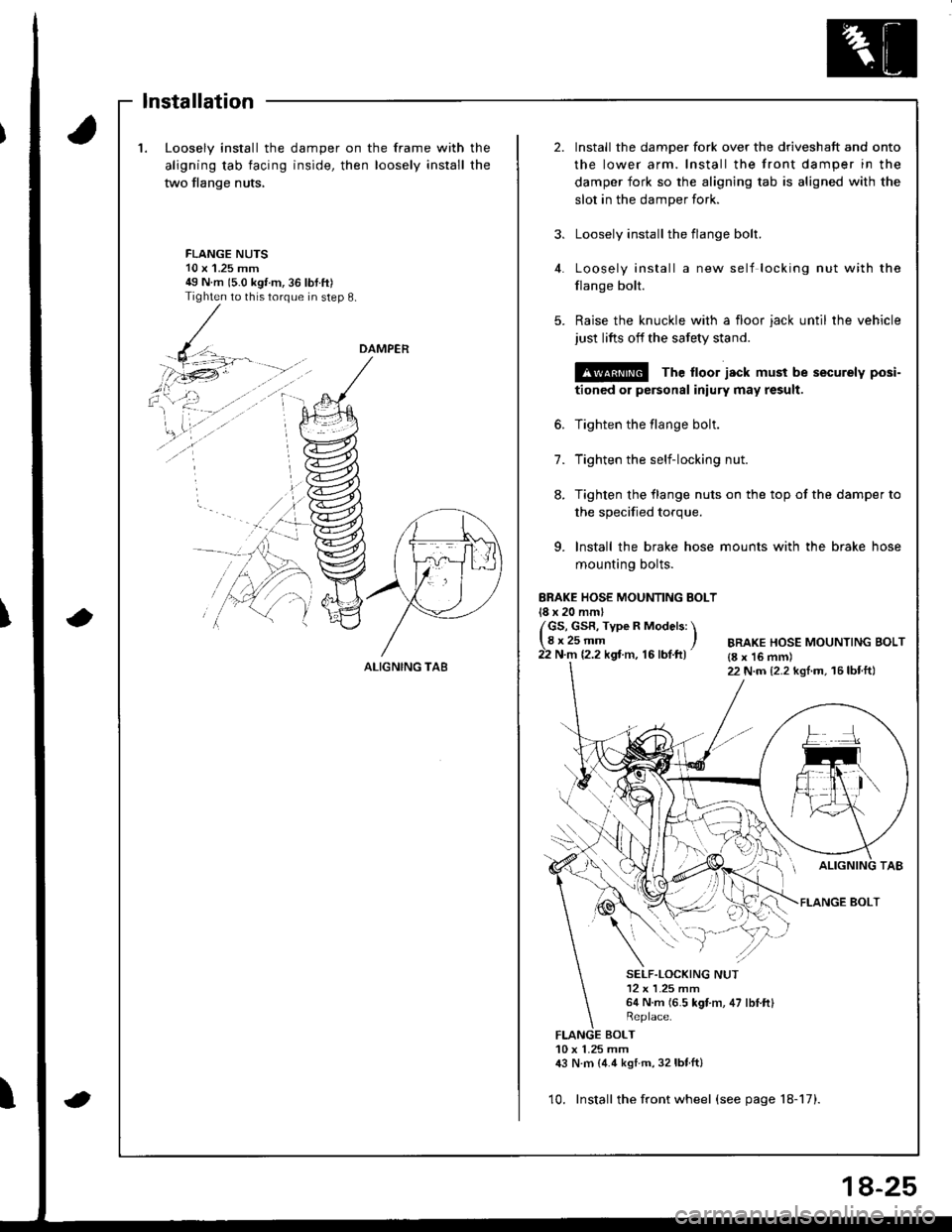
1.Loosely install the
aligning tab facing
two flange nuts,
damper on the frame with
inside, then loosely install
the
the
2.Install the damper fork over the driveshaft and onto
the lower arm. Install the front damper in the
damper fork so the aligning tab is aligned with the
slot in the damper fork.
Loosely install the flange bolt.
Loosely install a new self locking nut with the
flange bolt.
Raise the knuckle with a floor jack until the vehicle
just lifts off the safety stand.
@ The ltoor jack must be securely posi-
tioned or personal iniury may result.
Tighten the flange bolt.
Tighten the self-locking nut.
Tighten the flange nuts on the top of the damper to
3.
FLANGE NUTS10 x'1.25 mm49 N m 15.0 kgt m,36 lbtft)Tighten to this torque in step 8.
4.
5.
6.
7.
8.
the specified torque.
9. lnstall the brake hose mounts with the brake hose
mounting bolts.
ERAKE HOSE MOUNTING BOLT18 x 20 mml
/GS, GsR, Type R Models: \lgr25-- ,22 N.m 12.2 kgt m, 16 lbf.ft)BRAKE HOSE MOUNTING BOLT{8 x 16 mm)22 N.m {2.2 kgl.m, 16lbtft}
FLANGE BOLT
SELF.LOCKING NUT12 x L25 mm64 N.m (6.5 kgt m, 47 lbI.ftl
BOLT10 x 1.25 mm,|:} N.m {4.4 kstm, 32lbtft}
10. Install the front wheel (see page 18-17).
DAMPER
ALIGNING TA8
lnstallation
8-25
Page 738 of 1680
- Hub Bearing Unit
Removal
1. Loosen the wheel nuts slightly.
2. Raise the rear of vehicle, and support it with safety
stands in the proper locations (see section 1).
3. Remove the wheel nuts and rear wheel.
NOTE: Take care not to damage the hub uniton disassembly.
4. Pull the parking brake lever up.
5. Remove the hub cap.
6. Raise the locking tab on the spindle nut, then
remove the nut.
7. Remove the 6 mm brake disc retaining screws.
Replace.
8.
9.
Release the parking brake lever.
Remove the 6 mm flange bolts and caliper shield.
CALIPER SHIELDCheck for bending or damage.
6 mm FLANGE BOLTS
(cont'd)
18-29
Page 740 of 1680
- Hub Bearing Unit
4. Install the caliper shield with the 6 mm flange bolts.
6 mm FLANGE BOLTS9.8 N.m 11.0 kgI.m, 7 lbr.ftl
5. Tighten the 6 mm brake disc retaining screws,
6 mm BBAKE D|SC RETA|NTNG SCREWS9.8 N.m 11.0 kgf.m, 7.2 tbtftl
6. Install a new spindle nut, then tighten the nut.
7. Install a new hub cap.
8. Install the rear wheel with the wheel nuts.
NOTE: Before installing the wheel, clean the mating
surfaces of the brake disc and the wheel.
REAR WHEEL
WHEEL12 x 1.5 mm
SPINDLE NUT22 x 1.5 mm181 N.m {18.5 kgt.m. 134lbl.ftl
108 N.m 111.0 kg'f.m.80 lbf.tr)
Beplace.NOTE: After tightening, use a drift tostake the spindle nut shoulder againstthe spindle.
(cont'd)
18-31
Page 743 of 1680
Rear Suspension
Suspension Arms (cont'dl
Installation
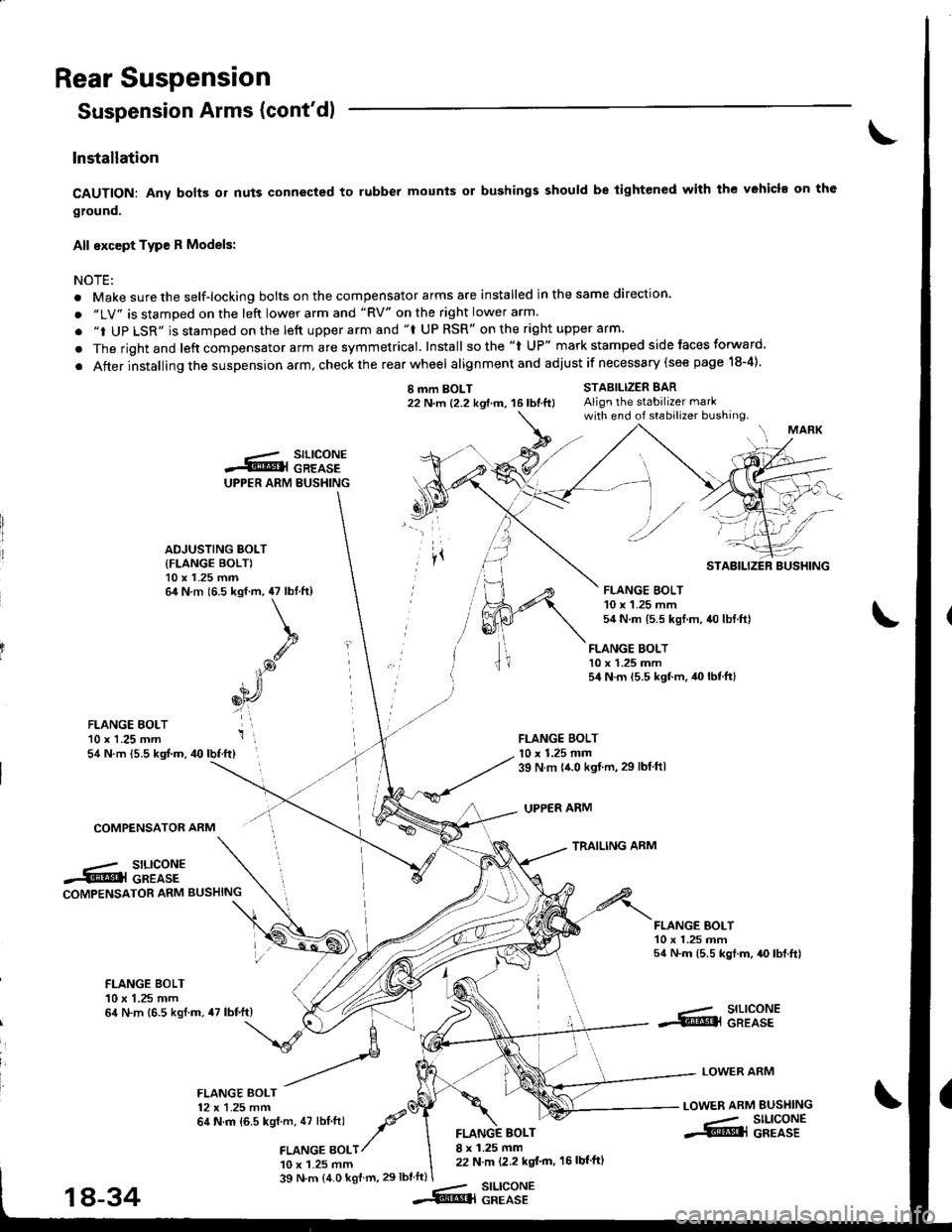
CAUTION: Any bolB or nuts connected to rubber mounts or bushings should be tightened with the vehicl. on th6
ground.
All except Type R Models:
NOTEi
. Make sure the self-locking bolts on the compensator arms are installed in the same direction.
. "LV" is stamped on the left lower arm and "RV" on the right lower arm.
. "i UP LSR" is stamped on the lett upper arm and "f UP RSR" on the right upper arm.
. The rightand left compensator arm are symmetrical. Install sothe "l UP" mark stamped side faces forward.
. After installing the suspension arm, check the rear wheel alignmentand adjust if necessary (see page 18-4).
I mm BOLT22 N.m {2.2 kgtm, 16lbtft}STABILIZER BARAlign the stabilizer markwith end of stabilizer bushing.
FLANGE BOLT10 x 1.25 mm54 N.m {5.5 kgf.m.40lbtft}
FLANGE BOLTl0 x 1.25 mm39 N m {{.0 kgt.m,29 lbtftl
UPPER ARM
TRAILING ARM
FLANGE EOLT'10 x 1.25 mm54 N.m {5.5 kgf.m, 40lbf.ft}
COMPENSATOR ARM
.-/ SILICONE.5tr@l GREASECOMPENSATOR ARM BUSHING
FLANGE BOI-T10 x 1.25 mm54 N.m (5.5 kgf.m, {O lbf.ft)
FLANGE BOLT10 x 1.25 mm64 N.m 16.5 kgl.m.47 lbf.ft)--- SILICONE.S!@l GREASE
LOWER ARM
LOWER ARM BUSI{ING
-- SILIGONE.S@l GREASE
FLANGE BOLT12 x 1.25 mm64 N.m {6.5 kgf m, 47 lbt.ftl -P'a
,amce gotr/
10 x 1.25 mm
BOLT8 x 1.25 mm22 N.m (2.2 kgt'm, 16 lbf'ftl
39 N.m (4.0 kgf m.29lbtft)stLtcoNEGREASE
UPPER ARM BUSHING
.-.- SILICONES@l GREASE
ADJUSTING BOLT
{FLANGE BOLT)10 x 1.25 mm64 N.m (6.5 kgf.m, 47 lbtft)
k
.g
iP
6[r,
i',
STABILIZER BUSHING
FLANGE BOLT10 x 1.25 mm54 N.m 15.5 kgt.m, 40 lbf.ftl
18-34--Rq
Page 744 of 1680
)Installation
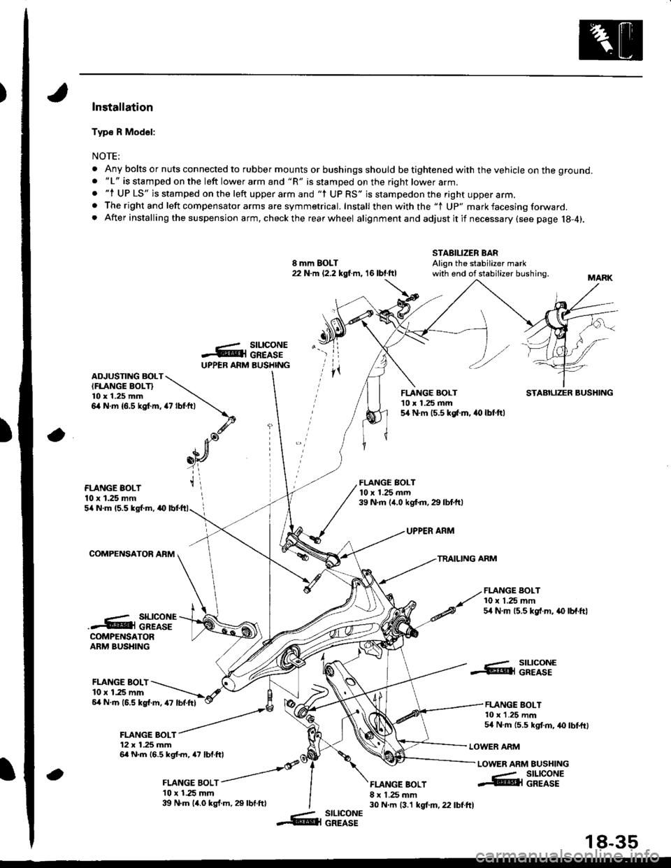
Typ€ R Model:
NOTE;
. Any bolts or nuts connected to rubber mounts or bushings should be tightened with the vehicle on the ground.. "L" is stamped on the left lower arm and "R" is stamped on the right lower arm.. "l UP LS" is stamped on the left upper arm and "l UP RS" is stampedon the right upper arm.. The right and left compensator arms are symmetrical. Install then with the "1 Up" mark facesing forward. After installing the suspension arm, checkthe rearwheel alignmentand adjustitif necessary(see page 18-4).
8 mm BOLT22 N.m (2.2 kgl m, 16 lbt.ftl
STABILIZER BARAlign the stabilizer markwith end of stabilizer bushing.
-ArUPPEB ARM
rz tot+,t \
\.d'. Ja),n[
_oY
t\
a
stLtcoNEGREASEBUSHINGADJUSTING BOLTIFLANGE BOLT}l0 x 1.25 mm6,4 N.m {6.5 kgt m,
FLANGE BOLT'10 x 1.25 mm5,[ N.m 15.5 kg[.m. 40 lbt.ftl
STABILIZER BUSHING
FLANGE BOLT10 x 1.25 mm
FLANGE BOLT10 x 1.25 mrn39 N.m (,r.0 kgf.m.29 lbtftl5/a N.m 15.5 kgl.m, a0
COMPENSATOR AFM
UPPER ARM
TRAILING ARM
FLANGE BOLT10 x 1.25 mm54 N.m 15.5 kgf.m, .{) lbf.ftl..- SILICONE.4@i cREAsECOMPENSATORARM BUSHING
FLANGE BOLI10 r 1.25 mm6,4 N.m (6.5 kgl.m, 47 lbf.Itl
FLANGE BOLT12 x 1.25 mm6a N.m 16.5 kgl.m, a7 lbf.ftl
, ror"orr /
l0 x 1.25 mm39 N.m 14.0 kgf.m, 29 lbt.ftl
FLANGE BOLT8 x 1.25 mm30 N.m 13.1 kgt m, 22 lbf.ftl
..- SILICONE.@ll GREASE
FLANGE BOLT10 x 1.25 mm54 N.m {5.5 kgt m, 40 lbtftl
LOWER ARM
LOWER ARM EUSHING
a
--- SILICONE@l GREASE
-- slLlcoNE&l GREASE
18-35
Page 749 of 1680

Rear Damper
Lower the rear suspension and position the damper
with the welded nut pointed toward the front of the
vehicle.
DAMPER
2. Loosely install the two flange nuts.
Hatchback:Sedan:
lnstallation
. ',.?7,:..r9\,ir '..
EY
FLANGE NUTS10 x 1.25 mmTighten these nuts in step 7 on the next page.
18-40
3. Install the wheel sensor wire bracket.
NOTE: Be careful when installing the sensors to
avoid twisting wires.
Raise the rear suspension with a floor iack until the
vehicle just lifts off the safety stand.
@ The floor jack must be securely posi-
tionod or personal iniury may result.
5. Install the damper mounting bolt and the flange
bolt, then tighten the bolts.
NOTE: The damper mounting bolt and the flange
bolt should be tightened with the damper under
vehicle load.
FLANGE EOLT10 x 1.25 m.n54 N.m (5.5 kgf m, 40 lbt.ftl
FLANGE BOLT10 x 1-25 mm54 N.m ls.s kgf m, 40 lbtft)
6. Tighten the three wheel sensor wire bracket bolts
{for vehicles with ABS).
9.8 N.m {1.0 kg{.m, 7.2 lbtftlBOLTS
Page 767 of 1680
Rear Brake Pads
Inspection and Replacement
Never use an air hose or dry b.ush to clean brake
assemblies.
Use an OSHA-approved vacuum cleaner to avoid
breathing brake dust.
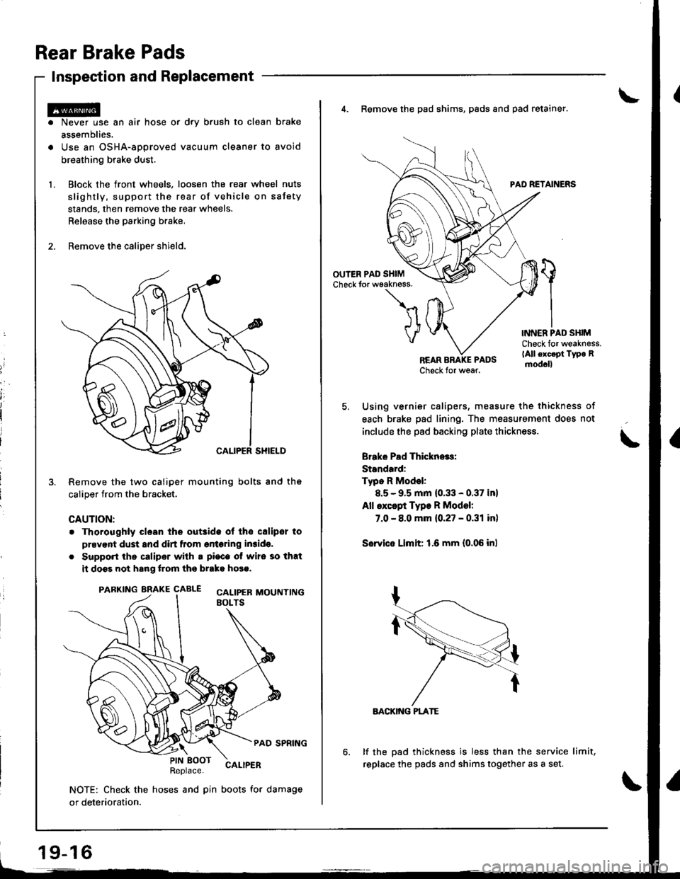
Block the front wheels. loosen tha rear wheel nuts
slightly, support the rear of vehicle on sstety
stands, then remove the rear wheels.
Relaase the parking brake,
Remove the caliper shield.
Remove the two caliper mounting bolts and the
caliper trom the bracket.
CAUTION:
. Thoroughly clesn the out3ide ol tho csliper to
prsvent dust and dirt from entering in3ido,
. Support the caliper with a pi€c€ ot wire so that
it doss not hang lrom ths brako hose.
PARKING BRAKE CAALE cALtpEB MOUTTT|NGEOLTS
PAD SPRING
Replace.CALIPER
NOTE: Check the hoses and pin boots for damage
or deterioration.
\PIN EOOT
19-16
4. Remove the pad shims, pads and pad retainer.
PAD RETAINERS
'l
VINNER PAD SHIMCheck for weakness.(All exc.pt Type Rmod.ll
Using vernier calipers, measure the thickness of
each brake pad lining. The measurement does not
include the pad backing plate thickness.
Brake Pad Thickn..s:
Standard:
Typo R Model:
8.5 - 9.5 mm (0.33 - 0.37 in)
All except Type R Model:
7.0 - 8.0 mm {0.27 - 0.31 in)
Sorvie Limit: 1.6 mm {0.06 inl
BACKIiIG PLATE
lf the pad thickness is less than the service limit,
replace the pads and shims together as a set.
Page 1129 of 1680
;
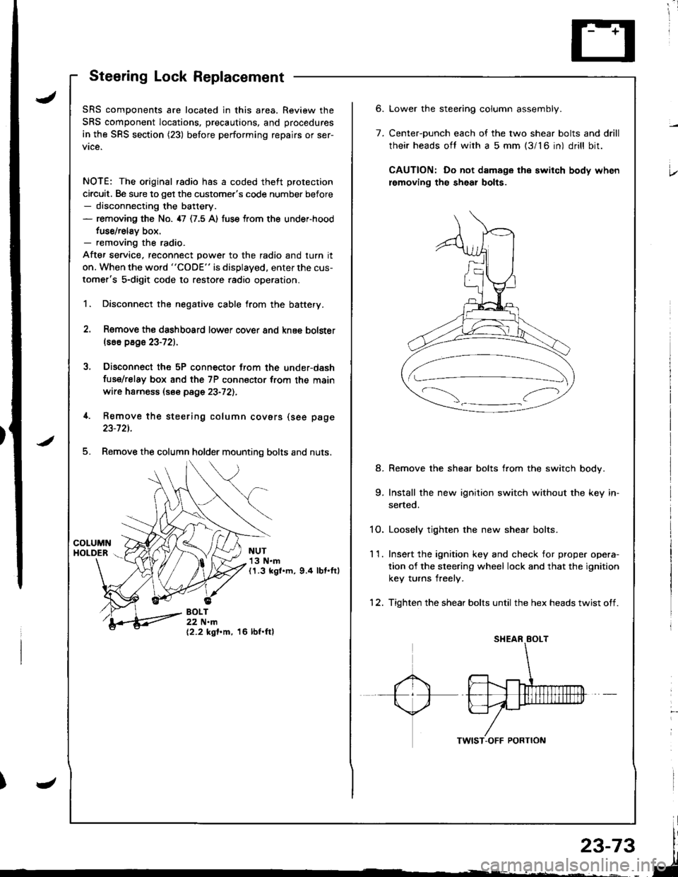
Steering Lock Replacement
SRS components are located in this area. Review the
SRS component locations, precautions, and procedures
in the SRS section (23) before performing repairs or ser-
vice.
NOTE: The original radio has a coded theft protection
circuit. Be sure to get the customer's code number before- disconnecting the battery.- removing the No. 47 (7.5 A) fuse trom the under-hood
fuse/relav box.- removing the radio.
After service, reconnect power to the radio and turn it
on. When the word "CODE" is displayed. enter the cus-
tomer's 5-digit code to restore radio operation.
1. Disconnect the negative cable from the battery.
2. Remove ths dsshboard lower cover and knee bolster(s6o p8ge 23-72).
3, Disconnect the 5P connector from the under-dash
fuse/relay box and the 7P connsctor from th€ main
wire harness (see page 23-72l.,
4. Remove the steering column covars (see page
23-721.
5. Remove the column holder mounting bolts and nuts.
NUT13 N.m(1.3 kgl.m, 9.4 lbt.ftl
BOLT22 N.m(2.2 kgf.m, 16 lbf.ftl
6.
7.
Lower the stee.ing column assembly.
Center-ounch each of the two shear bolts and drill
their heads oft with a 5 mm {3/16 in) drill bit.
CAUTION: Do not damage the switch body when
lemoving th€ sheal bolts.
Remove the shear bolts from the switch body.
Install the new ignition switch without the key in-
serted.
1O. Loosely tighten the new shear bolts.
11. Ins€rt the ignition key and check for proper opera-
tion of the sleering wheel lock and that the ignition
key turns freely.
12. Tighten the shear bolts until the hex heads twist off.
8.