1998 ACURA INTEGRA coolant reservoir
[x] Cancel search: coolant reservoirPage 195 of 1680

lllustrated Index
!$!!@ sv"t"m is under high plessure when the
engine is hot, To avoid dangei of releasing scalding
engine coolant, remove the cap only when engine is cool.
Total Cooling System Capacity {lncluding heater and
leservoir)
Bl8Bl engine:
MIT: 6.4 l. {6.8 US qt, 5.6 lmp qt)
Ant 6.7 t (7.1 US qt,5.9 lmp qt)
B18C1, 818C5 engines:
Mfi:6.7 t (7.1 US qt, 5.9 lmp qt)
CAUTION: lf any engine cgolant spills on painted por-
tions of the body, rinse it off immediately.
NOTE:
a Check all cooling system hoses for damage, leaks or
deterioration and replace il necessary.
a Check all hose clamps and retighten if necessary.
a Use new O-rings when reassembling.
RADIATOREngine coolant refilling and bleeding,page 10-6Leak test, page 10 8Inspecl soldered joints andseams for leaks,RAOIATOR CAPPressure test, page 10-8
UPPERRADIA
rl
]
CONDENSERFAN SHROUD{s€o section 22)
6 x 1.0 mm7 N.m {0.7 kgl.m, 5 lbf'ftl
5x0.8mm4.4 N.m (0.45 kgl.m,3.3 tbt.ft)
Blow out dirt from betweencore fins with compressed air.lf insects, etc., are cloggingradiator, wash them o{f withlow paessure water,
TOR HOSE
\*
\sffi((
@)
ATF COOLERHOSES181881 €ngin
S!g
R
U
COOLANTRESERVOIR
M/T: Manual lransmissionA/T: Automatic transmissionATF: Automatic t.ansmission fluid
FAN SHROUD
10-2
Page 199 of 1680

Radiator
Engine Coolant Refilling and Bleeding
CAUTION: When pouring engine coolant, be sure to shut
th6 relay box lid and not to l€t coolant spill on th6 el€c-
trical parts or the paint. lf any coolant spills, rinse it off
immediately.
1. Slide the heater temDerature control lever to maxi-
mum heat.
Make sure the engine and radiator are cool to the
touch.
2. Remove the radiator cap.
3. Loosen the drain plug, and drain the coolant.
4. Remove the drain bolt from the cvlinder block.
ji
Ii'
l:ll
ENGINE DRAIN EOLT78 N.m {8.0 kgt'm,54 lbt.ft)Apply liquid gasket tobolt thread when installing.WASHERReplace.
10-6
5. Apply liquid gasket to the drain bolt threads, then
reinstall the bolt with a new washer and tighten it
securely.
6. Tighten the radiator drain plug securely.
7. Remove, drain and reinstall the reservoir. Fillthe tank
halfway to the MAX mark with water, then up to
MAX mark with antifreeze.
COOLANTRESERVOIR
I
I
I
Page 200 of 1680

8.Mix the recommended antifreeze with an equal
amount of water in a clean container.
NOTE:
a Use only genuine Honda antifreeze/coolant.
a For best corrosion protection, the coolant concen-
tration must be maintained year-round at 500,6
minimum. Coolant concentrations less than 507o
may not provide sufficient protection against cor,
rosion or freezing.
a Coolant concentrations greater than 60% will im-
pair cooling efliciency and are not recommended.
CAUTION:
a Do not mix different brands of anti-lrcezel
coolants.
a Do not use additional rust inhibitots or anti-tustproducts; they may not be compatible with the
coolant.
Engine Coolant Refill Capacity [including reservoir
{0.6 { (0.6 US qt, 0.5 lmp qr)ll:
81881 engine:
Ml7:1-1t {/t.6 US qt. 3.9 lmp qtl
818B1, 818C1 engin€s:
AlTt 1.7 | 15.0 US qt, 4.1 lmp qt)
818C1, B18C5 engines:
MlTt 1.7 t 15.0 US $, 4.1 lmp qtl
FILLER NECK
9.Pour coolant into the radiator up to the base of the
tiller neck.
10. Startthe engine and let jt run until itwarmsup(the
radiator fan comes on at least twice).
1 1 . Turn olf the engine. Check the level in the radiator,
add coolant if needed.
'12. Put the radiator cap on tightly, then run the engine
again and check for leaks.
10-7
Page 1009 of 1680
.J
5.
6.
7.
8.
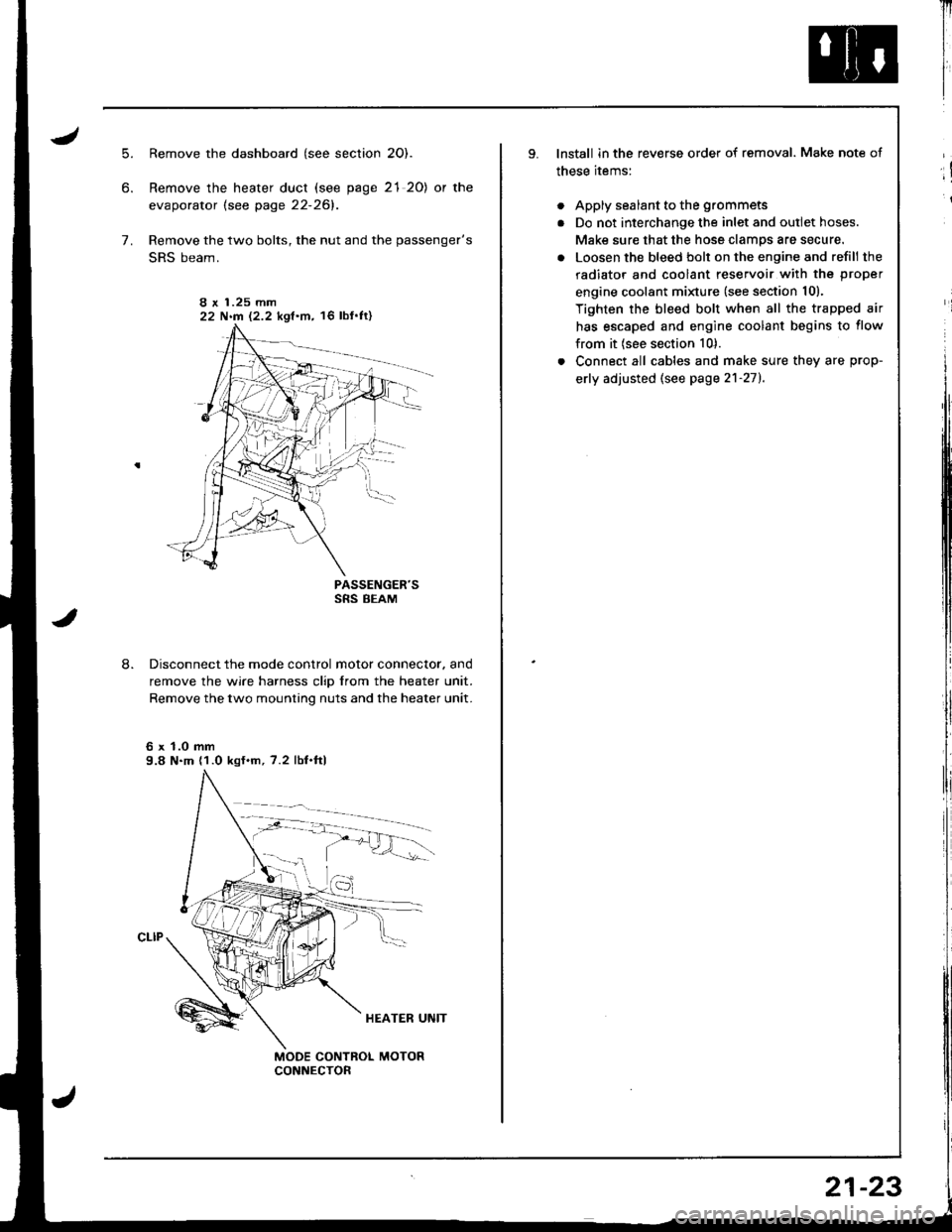
Remove the dashboard (see section 2O).
Remove the heater duct (see page 21 20) or the
evaporator lsee page 22-261.
Remove the two bolts, the nut and the passenger's
SRS beam.
PASSENGER'SSRS BEAM
Disconnect the mode control motor connector. and
remove the wire harness clip from the heater unit.
Remove the two mounting nuts and the heater unit.
6 x 1.0 mm9.8 N.m (1.0 kgf.m, 7.2 lbf.ftl
I r 1.25 mm22 N.m 12.2 kgf.m, 16 lbf'ft)
Il
I
I
lnstall in the reverse order of removal. Make note of
these items:
. Apply sealant to the grommets
. Do not interchange the inlet and outlet hoses.
Make sure that the hose clamps are secure.
. Loosen the bleed bolt on the engine and refill the
radiator and coolant reservoir with the proper
engine coolant minure (see section 10).
Tighten the bleed bolt when all the trapped air
has escaped and engine coolant begins to flow
from it (see section 10).
. Connect all cables and make sure they are prop-
erly adjusted (see page 2'l-271.
;!
i
21-23
Page 1054 of 1680
Condenser
J
Replacement
RADIATOR UPPERMOUNT BRACKETS
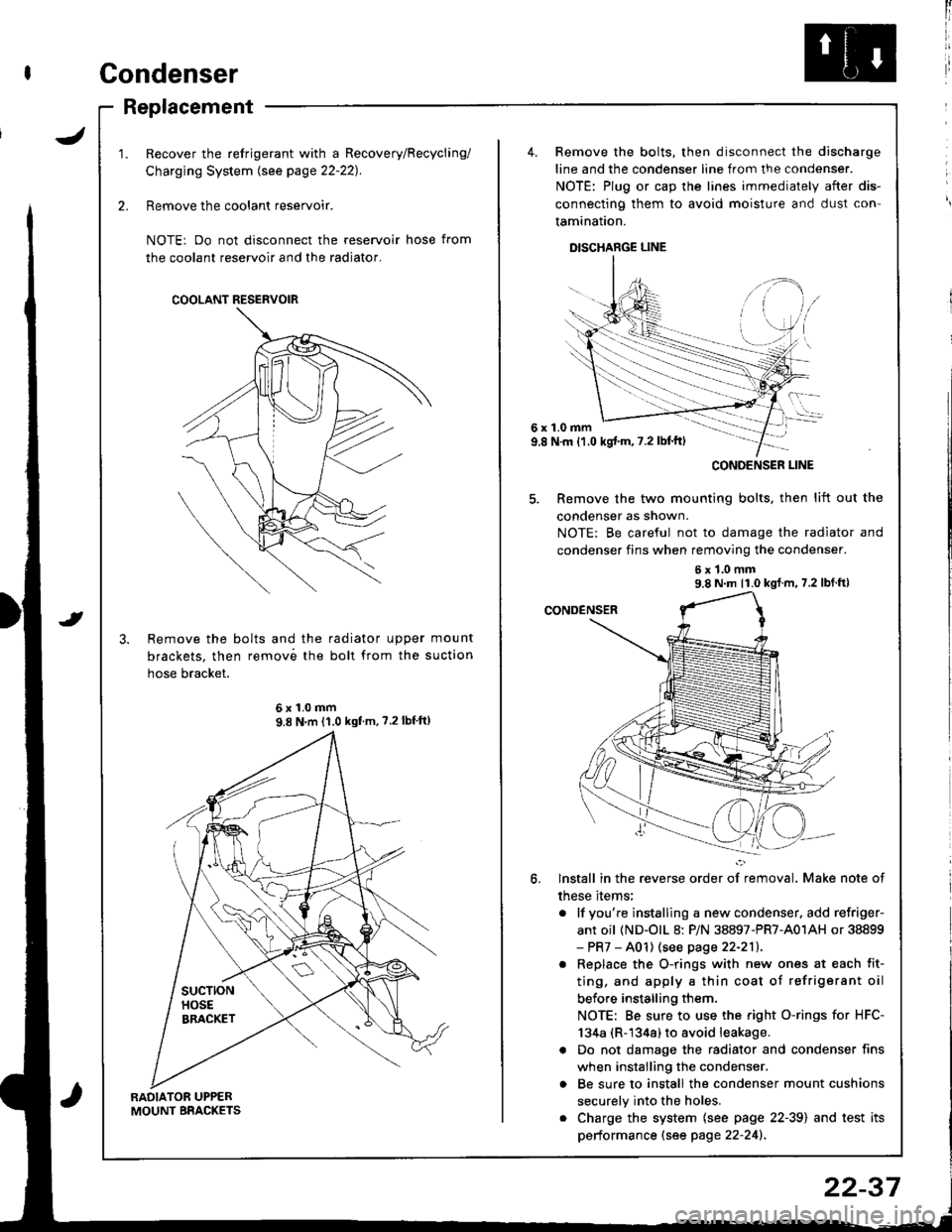
Recover the refrigerant with a Recovery/Recycling/
Charging System lsee page 22-221.
Remove the coolant reservoir.
NOTE: Do not disconnect the reservoir hose from
the coolant reservoir and the radiator.
Remove the bolts and the radiator upper mount
brackets. then remov6 the boll from the suction
hose bracket.
COOLANT RESERVOIR
6x1.0mm9.8 N'm 11.0 kgf'm, ?.2lbf'ft)
4. Remove the bolts, then disconnect the discharge
line and the condenser line from the condenser.
NOTE: Plug or cap the lines immediately after dis-
connecting them to avoid moisture and dust con'
tamination.
DISCHARGE LINE
6x1.0mm9.8 N.m {1.0 kgj'm, 7.2 lbl'ft)
5. Remove the two mounting bolts, then lift out the
condenser as shown.
NOTE: Be careful not to damage the radiator and
condenser fins when removing the condenser.
6x1.0mm9.8 N m 11.0 kgf m, 7.2 lbf ft)
lnstall in the reverse order of removal. Make note of
these items;
. lf you're instslling a new condenser, add refriger-
ant oil (ND-olL 8: P/N 38897-PR7-A01AH or 38899- PR7 - A01) (see page 22-211.
. Replace the O-rings with new ones at each fit-
ting, and apply a thin coat of refrigerant oil
before installing them.
NOTE: Be sure to use the right O-rings for HFC-
134a (R-1344) to avoid leakage.
a Do not damage the radiator and condenser fins
when installing the condenser.
o Be sure to install the condenser mount cushions
securely into the holes.
. Charge the system {see page 22-39) and test its
performance (see page 22-241.
CONOENSER LINE
22-37
Page 1647 of 1680
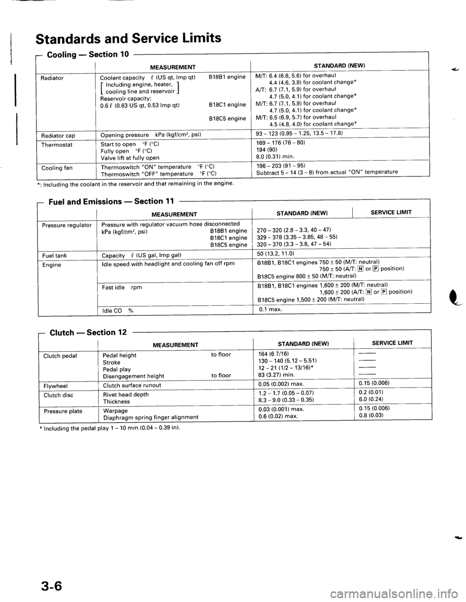
Standards and Service Limits
missions - Section 11
* Including the pedal play 1 - 10 mm (0.04 - 0.39 in).
0Gooling - Sectlon
MEASUREMENTSTANDARD (NEW}
RadiatorCoolant capacity / (US qt, lmp qt) 81881 engine
I Including engine, heater, II cooling line and reservoir IReservoir capacity:0.6 f (0.63 US qt, 0.53 lmp qt) 818C1 engine
818C5 engine
M/T: 6.4 (6.8, 5.6) for overhaul4.4 14.6,3.9) for coolant change*
A,/T: 6.7 (7.1, 5.9) for overhaul4.7 $.0,4.1)for coolant change*
M/T: 6.7 (7.1,5.9) for overhaul4.7 (5.0, 4.1) for coolant change*
M/T: 6.5 (6.9, 5.7) for overhaul4.5 (4.8, 4.0) for coolant change*
Radiator capOpening pressure kPa (kgf/cm'�, Psi)93 - 123 (0.95 - 1.25, 13.5 - 17.8)
ThermostatStart to open 'F ("C)
Fully open "F ("C)
Valve lift at fully open
169 - 176 (76 - 80)194 (90)
8.0 (0.31)min.
Cooling fanThermoswitch "ON" temperature "F ('C)
Thermoswitch "OFF" temperature "F ("C)196 - 203 (91 - 95)Subtract 5 - 14 (3 - 8) from actual "ON" temperature
*: Including the coolant in the reservoir and that remaining in the engine
Fuel and E
MEASUREMENTSTANDARD (NEW}SERVICE LIMIT
Pressure regulatorPressure with regulator vacuum hose disconnected
kPa (kgf/cm'�, psi) 81881 engine818C1 engine818C5 engine
270 - 320 (2.8 - 3.3, 40 - 47].
329 - 378 (3.35 - 3.85, 48 - 55)
320 - 370 (3.3 - 3.8, 47 -541
Fuel tankCapacity / (US gal, lmp gal)50 (13.2, 11.0)
Engineldle speed with headlight and cooling fan off rpm81881, 818C1 engines 750 t 50 (M/T: neutral)750 I 50 (A/T: N or E Position)818C5 engine 800 t 50 (M/T: neutral)
Fast idle rpmB1881, 818C1 engines 1,600 t 200 (M/T: neutral)1,600 t 200 (A/T: E or E Position)818C5 engine 1,500 t 200 (M/T: neutral)
ldle CO %0.1 max.
Clutch - Section 'lZ
MEASUREMENTSTANDARD (NEW}SERVICE LIMIT
Clutch pedalPedal height to floor
StrokePedal playDisengagement height to floor
164 (6 7/16)130 - 140 (5.12 - 5.51)12 -21 (12 - 13/16)*83 (3.27) min.
FlywheelClutch surface runoul0.05 (0.002) max,0.15 (0.006)
Clutch discRivet head depthThickness
1.2 - 1.7 (0.05 - 0.07)8.3 - 9.0 (0.33 - 0.35)0.2 (0.01)
6.0 (0.24)
Pressu re plateWarpageDiaphragm spring finger alignmenl
0.03 (0.001) max.0.6 (0.021 max.
0.15 (0.006)
0.8 (0.03)
3-6
Page 1670 of 1680
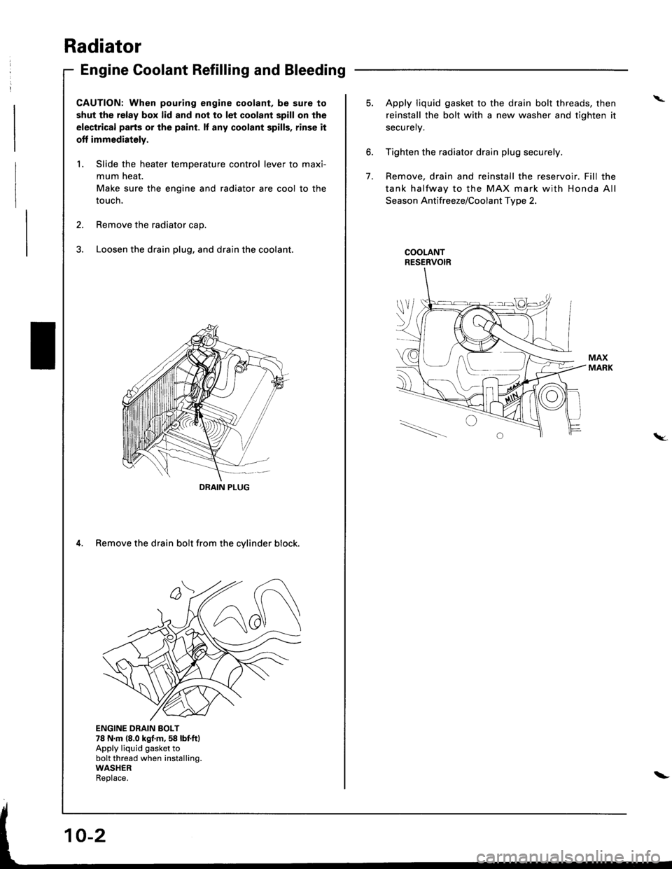
Radiator
Engine Goolant Refilling and Bleeding
CAUTION: When pouring engine coolant, be sure to
shut the relay box lid and not to let coolant spill on the
electrical parts or the paint. lf any coolant spills, rinse it
off immediately.
1. Slide the heater temperature control lever to maxi-
mum heat.
Make sure the engine and radiator are cool to the
touch.
2. Remove the radiator caD.
3. Loosen the drain plug, and drain the coolant.
4. Remove the drain bolt from the cylinder block.
ENGINE DRAIN BOLT78 N.m (8.0 kgf.m,58 lbf.ftlApply liquid gasket tobolt thread when installing.WASHERReolace.
DRAIN PIUG
I \.--
\_-l - I
\
6.
7.
5. Apply liquid gasket to the drain bolt threads, then
reinstall the bolt with a new washer and tighten it
securely.
Tighten the radiator drain plug securely.
Remove, drain and reinstall the reservoir. Fill the
tank halfway to the MAX mark with Honda All
Season Antifreeze/Coolant Type 2.
COOLANTRESERVOIR
tW.
\-
Page 1671 of 1680
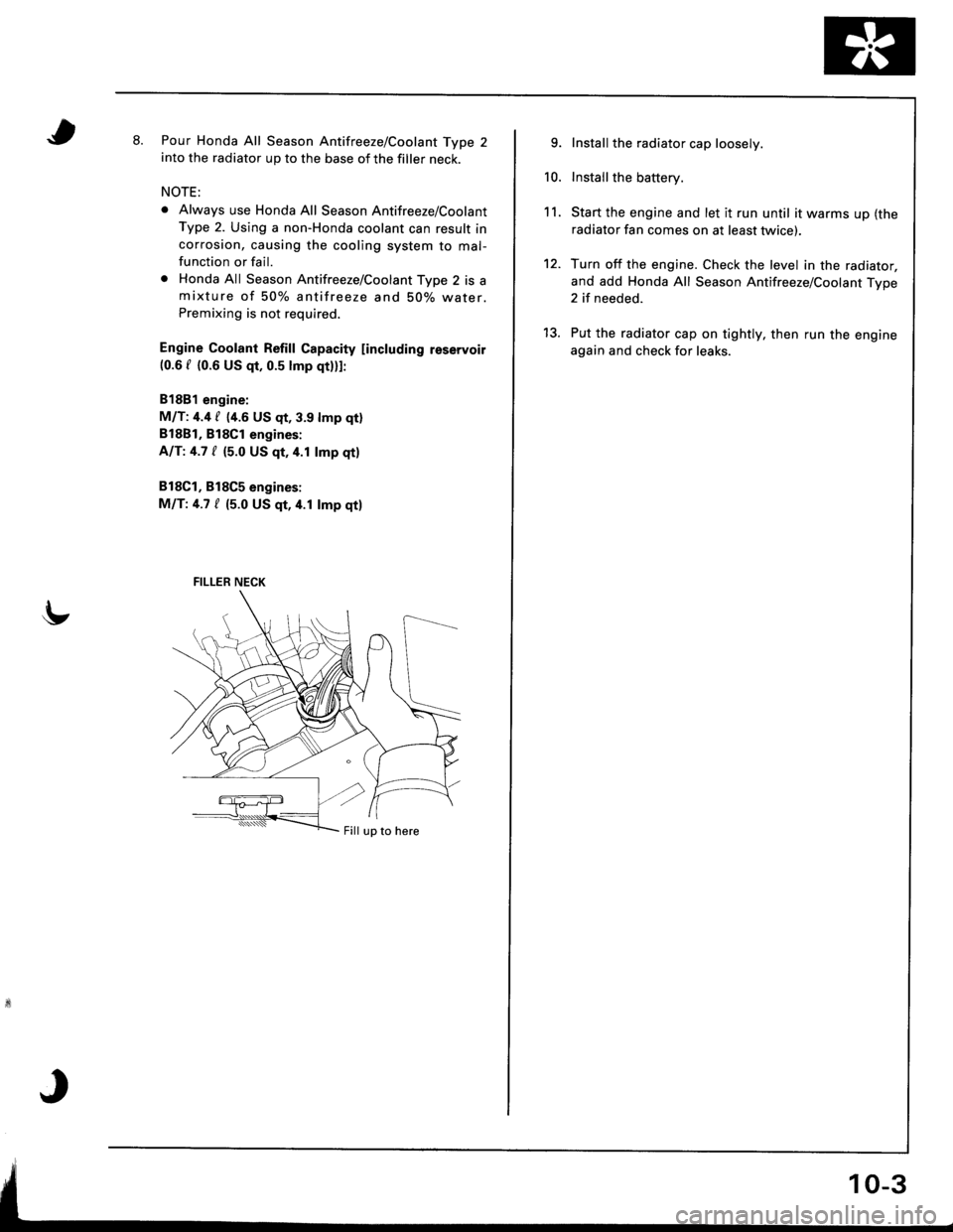
tt.Pour Honda All Season Antifreeze/Coolant Type 2into the radiator up to the base of the filler neck.
NOTE:
o Always use Honda All Season Antifreeze/Coolant
Type 2. Using a non-Honda coolant can result incorrosion, causing the cooling system to mal-function or fail.
o Honda All Season Antifreeze/Coolant Type 2 is amixture of 50% antifreeze and 50% water.Premixing is not required.
Engine Coolant Refill Gapacity [including reservoir(0.6 f {0.6 US qt, 0.5 lmp qtlll:
81881 engine:
M/T: 4.4 / {4.6 US qt, 3.9 lmp qtl
B18B1, Bl8Cl engines:
AIT:4.7 / (5.0 US qt,4.1 lmp qtl
818C1, B18C5 engines:
MIT:4.7 / (5.0 US qt,4.1 lmp qtl
FILLER NECK
Fill up to here
9.
10.
11.
12.
Install the radiator cap loosely.
Install the battery.
Start the engine and let it run until it warms up (the
radiator fan comes on at least twice).
Turn off the engine. Check the level in the radiator,
and add Honda All Season Antifreeze/Coolant Type2 if needed.
Put the radiator cap on tightly, then run the engine
again and check for leaks.
13.