1998 ACURA INTEGRA value
[x] Cancel search: valuePage 668 of 1680

Inspection and Adjustment
Pump Belt
NOTE: When using a new belt, first adjust the deflection
or tension to the values for the new belt, then readjust
the deflection or tension to the values for the used belt
after running engine for five minutes,
Inspection
Attach the soecial tool to the belt and measure the ten-
sion of the belt.
Tension:
Usad Belt: 390 - 54O N {/10 - 55 kgf. 88 - 120 lbf}
Nsw Belt: 740 - 880 N {75 - 90 kgf. 170-2(X)lbf)
NOTE:
. lf there are cracks or any damage evident on the belt,
replace it with a new one.
. Follow the manufacturer's instructions for the tension
gauge.
ii
:i
i
I
,;h
,lt l
I
i
CRANKSHAFT PULEYBELT TENSION GAUGE07JGG - 001010A
Inspect the pump belt for cracks or any damage.
Replace the belt with a new one if necessary.
Mea3urement without Bah Tonsion Gaugo:
Apply a force of 98 N {10 kgt,22 lbll and measure the
deflection between the power steering pump and the
crankshaft pulleys,
Drllection:
Us.d B6h: 11.5 - 13.5 mm (0.45 - 0.53 in)
New Bsh: 8.0 - 10.0 mm 10.31 - 0.39 inl
POWER STEERING PULLEY
17-20
Adiustment
1. Loosen the power steering pump mounting bolts.
2. Turn the adjusting bolt to get the proper belt ten-
sion, then retighten the bolts.
3. Stan the engine and turn the steering wheel from
lock-to-lock several times. then stop the engine and
recheck the deflection of the belt.
24 N.m l2.a kgf.m, 17 lbf.ftl
Page 858 of 1680
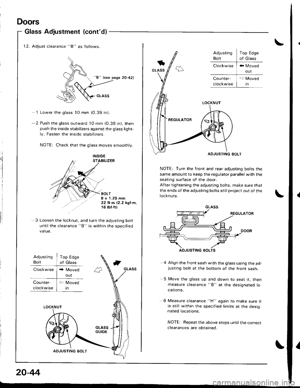
12. Adjust clearance "8" as follows.
)^
d "8" {see pase 20-42}
(6
:\D \crnss
1 Lower the glass 1O mm (0.39 in).
2 Push the glass outward lO mm (0.39 in), thenpush the inside stabilizers against the glass light-
ly. Fasten the inside stabilizers.
NOTE: Check that the glass moves smoothly.
i
ilINSID€STAEILIZER
BOLT8 x 1.25 mm22 N.m 12.2 kgl.m,16 tbt ftl
3 Loosen the lo"knrt, "nd turn the adjusting bolt
until the clearance "B" is within the specilied
value.
Adiusting
Bolt
Clockwise
Top Edge
of Glass
Counter-
cloc kwise
LOCKNUT
ADJUSTING BOLT
20-44
Doors
Glass Adjustment (cont'd)
out
\
LOCKNUT
REGULATOR
ADJUSTING BOLT
NOTE: Turn the front and rear adjusting bolts the
same amount to keep the regulator parallel with the
seating sur{ace ot the door.
After tightening the adjusting bolts, make sure that
the ends of the adjusting bolts still project out of the
locknuts.
4 Align the front sash with the glass using the ad-justing bolt at the bottom of the lront sash.
5 Move the glass up and down to seat it, thenmeasure clearance "B" at the designated locations.
6 Measure clearance "H" again to make sure itis still within the specified limirs at the desig,nated locations.
NOTE: Repeat the above steps until the correct
clearances are obtained.
Top Edge
of Glass
GLASS
ADJUSTING BOLTS
I
Page 860 of 1680
Doors
Glass Adjustment (cont'dl
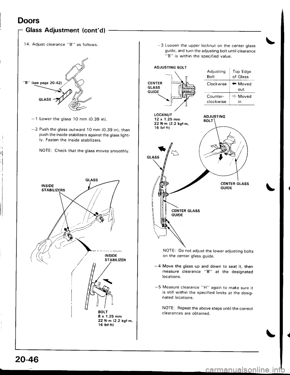
'14. Adiust clearance "B" as Jollows.
"8" lsee page 20-421
- 1 Lower the glass 1O mm (0.39 in).
2 Push the glass outward 10 mm 10.39 in), thenpush the inside stabilizers against the glass light-ly. Fasten the inside stabrIzers.
NOTEr Check that rhe glass moves smoothly.
BOLT8 x 1.25 mm22 N.m (2.2 kgf.m,'t6 tbt.fr)
20-46
-
-.\
CENTER [L\LGLAss lilffiGUTDE I li$lliun
\fiJrtrlAl-,/"
.-3 Loosen the upper locknut on the center glassguide, and turn the adjusting bolt until clearance"B" is within the specified value.
ADJUSTING BOLT
LOCKNUT
22 N.m 12.2 kgt tn,16 lb{.ttl
*
GLASS
NOTE: Do not adjust the lower adjusting boltson the center glass guide.
-4 Move the glass up and down to seat jt, then
measure clearance "B" at the designatedlocations.
- 5 Measure clearance "H" again to make sure itis still within the specified limits ar the desig,nated locations.
NOTE: Repeat the above steps until the correctclearances are obtained.
Top Edge
of Glass
Page 1334 of 1680
)
Precautions/Procedures
General Precautions
Carefully inspect any SRS part before you install it,
Do not install any part that shows signs of being drop-
ped or improperly handled. such as dents, cracks or
deformstion:
- Airbags- Cable reel- SRS unit
' Use only a digital multimeter to check the system lf
it's not a Honda multimeter. make sure its output is
10 mA (0.01 A) or less when switched to the smallest
value in the ohmmeter range. A tester with a higher
output could damage the airbag circuit or cause acci-
dental deployment and possible injury.
r Do not install used SRS parts from anothercar.When
making SRS repairs, use only new parts.
r Except when performing electrical inspections,
always disconnect both the negative cable and posl-
tive cable from the batterY, and wait at least three
minutes before beginning work.
r Replacement of the combination light and wiper/
washer switches and cruise control switch can be
done without removing the steering wheel:
- Combination light and wiperlwasher switch replace-
ment (see page 23-268).- Cruise controi sevresume switch replacement (see
page 23-259t�.
. Whenever the ignition switch is ON (ll), or has been
turned OFF for less than three minutes, be caretul not
to bump the SRS unit; the airbags could accidentally
deploy and cause damage or iniuries.
. Whenever the airbag has been activated, replace the
SRS unit.
. The original radio has a coded theft protection circuit.
Be sure to get the customer's code number beJore dis-
connecting the battery cables.
23-281
Airbag Handling and Storage
Do not try to disassemble the airbag. lt has no service-
able parts. Once an airbag has been operated
(deployed), it cannot be repaired or reused.
For temporary storage of the airbag during service,
please observe the following precautions:
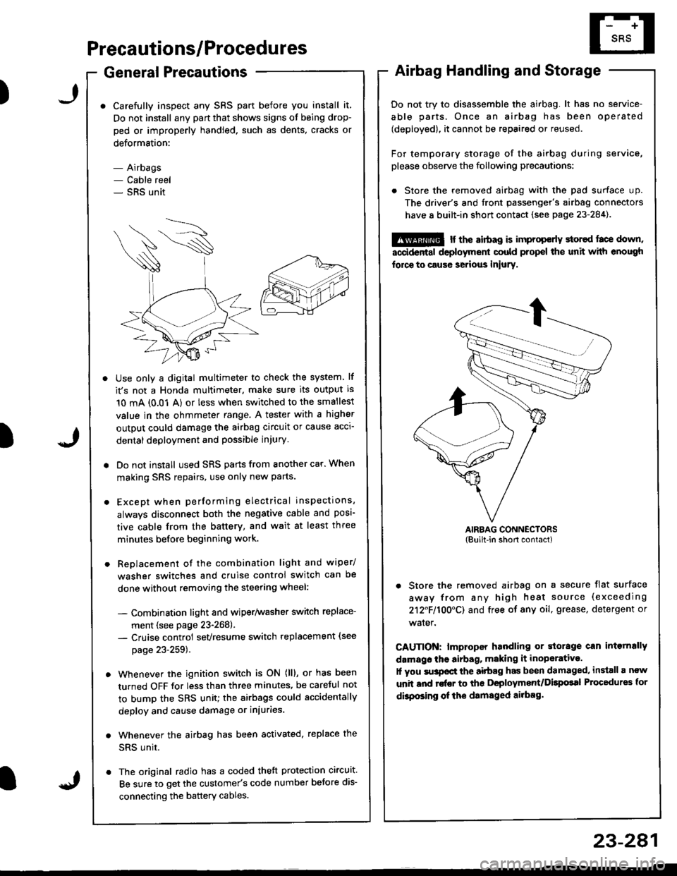
. Store the removed airbag with the pad surface up.
The driver's and tront passenger's airbag connectors
have 8 built-in short contact (see page 23-284).
@ r the airbag is improp€rly storcd face down,
accidental deployment could propel the unit with enough
force to caus6 serious iniury.
AIRBAG CONNECTORS(Built-in short contact)
. Store the removed airbag on a secure flat surface
away from any high heat source (exceeding
212F110O'CI and free of any oil, grease, detergent or
water.
CAUTION: lmproper handling or storage can intornally
damags the airbag, making it inoperative.
1l you su3pocl the aitbag has been damaged, install a ncw
unit and rofEr to ths Deployment/Dilpolal Procedures for
dbposing of ihe damsged ailbag.
)
Page 1340 of 1680
)
Troubleshooting
Self-diagnostic Procedures
The self-diagnostic function of the SRS system allows it to locate the causes of system problems and to store this informa-
tion in memorv. For easier troubleshooting, this data can be retrieved via 8 dats link circuit.
o When you turn the ignition switch ON (ll), the SRS indicator will come on. lf it goes off after six seconds, the system is
normat.
. lf there is 8n abnormality, the system locstes and defines the problem, stores this information in memory, and turns
th€ SRS indicator light on. The data will remain In the memory even when the ignition switch is turned off or if the bat-
terv is disconnected.
. When you connect the SCS service connector to the service check connector (2P), and turn the ignition switch ON {ll),
the sRs indicator light will indicate the diagnostic trouble code (DTCI by th€ number of blinks.
. After reading and recording the DTC, proceed with the troubleshooting for this code
Pr6crution!
. Use only a digital multimeter to check the system, lf it's not a Honda multimeter, make sure its output is 10 mA (0.01 A)
or less when switched to the smallest value in the ohmmeter range. A tester with a higher output could damsge the
airbag circuit or cause sccidental airbag deployment and possible injury.
. Whenever the ignition switch is ON (ll), or has been turned OFF for less than three
SRS unit; the airbags could accidentally deploy and cause damage or injuries'
. Before you remove the SRS main harness, disconnect the driver's airbag connector
conneclor.
and the front passenger's airbag
. Make sure the battery is sufficiently charged (s6e psge 23-67). lf the battsry is dead or low, msasuring values won't be
correct,
a Do not touch a tester probe to the terminals in the SRS unit or harness connectors, and do not connect the terminals
with a jumper wire. Use only the backprobe set and the SCS service connector.
For backprobing spring-loaded lock type connectors, refer to psge 23-283.
Reading the DTC
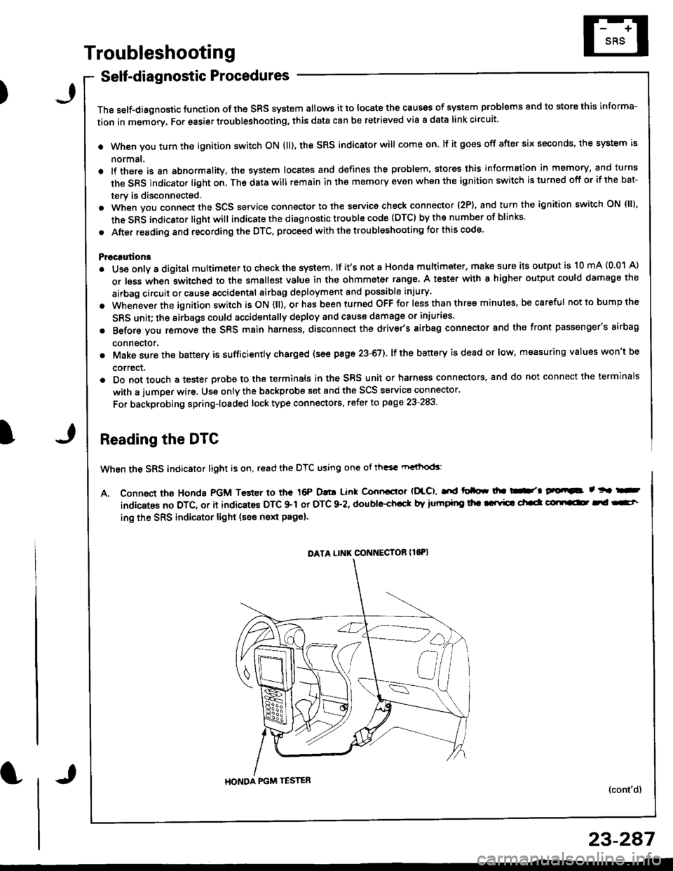
When the SRS indicator light is on, read the DTC using one ot th"sc rn"ihod<
A. Connect the Honda PGM Toster io the 16P D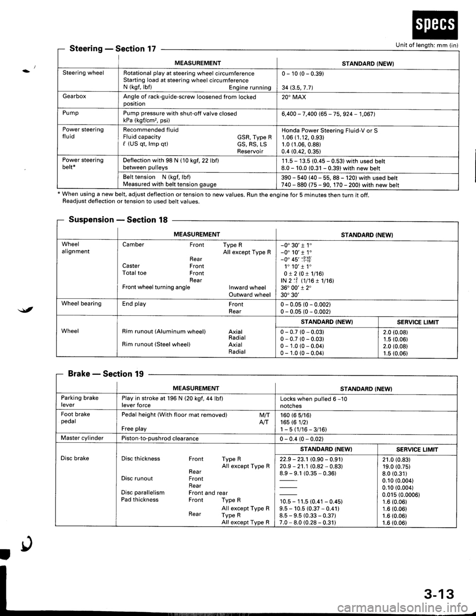
MEASUREMENTSTANDARD (NEWI
Steering wheelRotational play at steering wheel circumferenceStarting load at steering wheel circumferenceN (kgf, lbf) Engine running
0 - 10 (0 - 0.39)
34 (3.5,7 .71
GearboxAngle of rack-guide-screw loosened from lockedoosition20'MAX
PumpPump pressure with shut-off valve closedkPa (kgf/cm,, psi)6,400 - 7,400 (65 - 75, 924 - 1,067],
Power steeringfluidRecommended fluidFluid capacity GSR, Type Rf (US qt, lmp qtl cS, RS, LSReservoir
Honda Power Steering Fluid-V or S1.06 (1.12,0.93)
1.0 (1.06,0.88)
0.4 (0.42, 0.35)
Power steeringbelt*Deflection with 98 N (10 kgf,22 lbflbetween pulleys1 1.5 - 13.5 (0.45 - 0.531 with used belt8.0 - 10.0 (0.31 - 0.39) with new belt
Belt tension N (kgf, lbf)Measured with belt tension gauge390 - 540 (40 - 55, 88 - 120) with used belt740 - 880 (75 - 90, 170 - 2001with new belt
SteeringSection 17
* When using a new belt, adjust deflection or tension to new values. Run the engine for 5 minutes then turn it off.Readiust deflection or tension to used belt values.
Suspension - Section 18
BrakeSection 19
Unit of length: mm (in)
$t
MEASUREMENTSTANDARD (NEWI
WheelalignmentCamber Front Type RAll except Type RRearCaster FrontTotal toe FrontRearFront wheel turning angle Inward wheelOutward wheel
-0'30'r 1"-0' 10'r 1.-0" 45'�1?:i3i1. 10'�1 1.0!210!1116!,lN 2 lf (t7t6 1 1716136. 00'1 2"30'30'
Wheel bearingEnd play FrontRear0 - 0.05 (0 - 0.002)0 - 0.05 (0 - 0.002)
WheelRim runout (Aluminum wheel) AxialRadialRim runout (Steel wheel) AxialRadial
STANDARD (NEW}SERVICE LIMIT
0 - 0.7 (0 - 0.03)0 - 0.7 (0 - 0.03)0 - 1.0 (0 - 0.04)0 - 1.0 (0 - 0.04)
2.0 (0.08)
1.5 (0.06)2.0 (0.08)1.5 (0.06)
MEASUREMENTSTANDARD (NEW}
Parking brakeleverPlay in stroke at 196 N (20 kgf,44 lbf)lever forceLocks when oulled 6 -10
notches
Foot brakepedalPedal height (With floor mat removed)
Free play
M/TAtT160 (6 5/161165 rc 1nl1-5(1/16-3/16)
Master cylinderPiston-to-oushrod clearance0 - 0.4 (0 - 0.021
Disc brakeDisc thickness Front Type RAll except Type RRearDisc runout FrontRearDisc parallelism Front and rearPad thickness Front Type R
All except Type RRear Type RAll except Type R
STANDARD (NEWISERV]CE LIMIT
22.9 - 23.1 (0.90 - 0.91120.9 - 21.1 (0.82 - 0.83)
1= t (0.35-0.361
10.5 - 11.5 (0.41 - 0.45)9.5 - 10.5 (0.37 * 0.41)8.5 - 9.5 (0.33 - 0.37)7.0 - 8.0 (0.28 - 0.31)
21.0 (0.83)19.0 (0.75)
8.0 (0.31)
0.10 (0.004)
0.10 (0.004)
0.015 (0.0006)1.6 (0.06)
1.6 (0.06)1.6 (0.06)
1.6 (0.06)
Page 1655 of 1680
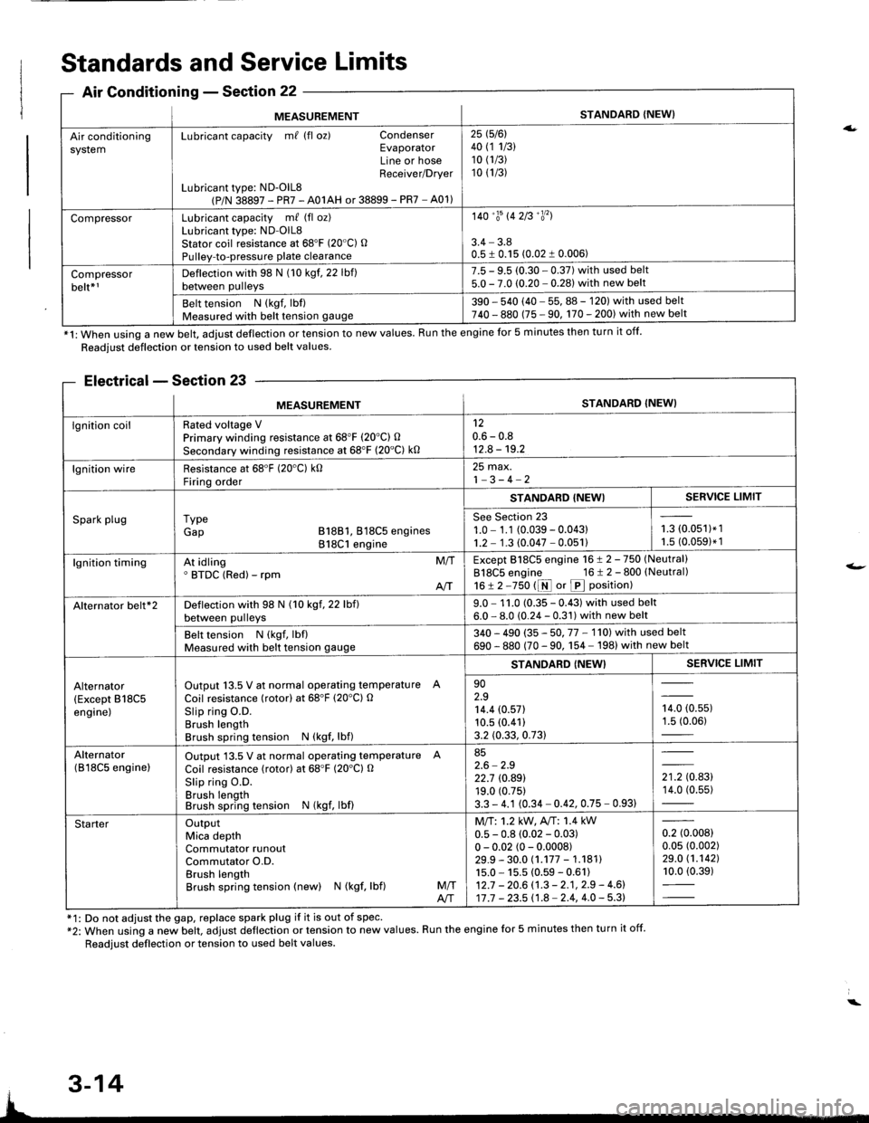
ng
MEASUREMENTSTANDARD {NEW}
Air conditioningsystemLubricant capacity m/ (fl oz) CondenserEvaporatorLine or hoseReceiver/Drver
Lubricant type: ND-OlL8(P/N 38897 - PR7 - A01AH or 38899 - PR7 - A01)
25 1516l40 (1 1/3)10 (1/3)
10 (1/3)
CompressorLubricant capacity m/ (fl oz)Lubricant type: ND-OlL8Stator coil resistance at 68'F (20"C) OPulley-to-pressure plate clearance
140'�trs 142B'�y'�l
3.4 - 3.80.5 I 0.15 (0.02 1 0.006)
Compressorbelt*rDeflection with 98 N (10 kgf. 22 lbf)between pulleys
7.5 - 9.5 (0.30 - 0.37) with used belt5.0 - 7.0 (0.20 - 0.281 with new belt
Belt tension N (kgf, lbf)Measured with belt tension gauge390 - 540 (40 - 55, 88 - 120) with used belt740 - 880 (75 - 90, 170 - 200) with new belt
*1: When using a new belt, adjust deflection or tension to new values. Run the engine for 5 minutes then turn it off.
Standards and Service Limits
Air Conditionins - Section 22
Readjust deflection or tension to used belt values.
Electrical - Section 23
f1: Do not adjust the gap, replace spark plug if it is out of spec'*2: When using a new belt. adjust deflection or tension to new values. Run the engine for 5 minutes then turn it off.
Readjust deflection or tension to used belt values.
a.
t-
MEASUREMENTSTANDARD (NEW}
lgnition coilRated voltage VPrimary winding resistance at 68"F (20'C) O
Secondary winding resistance at 68'F (20"C) k0
120.6 - 0.812.8 - 19.2
lgnition wireResistance at 68'F (20'C) k0Firinq order
25 max.1-3-4-2
Spark plugI ypeGap B18B1, 818C5 engines818C1 engine
STANDABD {NEWISERVICE LIMIT
See Section 231.0 - 1.1 (0.039 - 0.04311.2 - 1.3 (0.047 - 0.051)i-= roru',t.',1.5 (0.0591* 1
lgnition timingAt idling' BTDC (Red) - rpmM/T
AIT
Except 818C5 engine 16 ! 2 -750 (Neutral)
818C5 engine 16 t 2 - 800 (Neutral)
16!2-750 t1r{ or p position)
Alternator belt*2Deflection with 98 N (10 kgf, 22 lbf)between pulleys9.0 - 1 1.0 (0.35 - 0.43) with used belt6.0 - 8.0 (0.24 - 0.31) with new belt
Belt tension N (kgf, lbflMeasured with belt tension gauge340 - 490 (35 - 50. 77 - 1'l0l with used belt
690 - 880 (70 - 90. 1 54 - 198) with new belt
Alternator(Except B18C5engine)
Output 13.5 V at normal operating temperature A
Coil resistance (rotor) at 68'F (20'C) OSlip ring O.D.Brush lengthBrush spring tension N (kgf, lbf)
STANDARD {NEW}SERVICE LIMIT
902.914.4 (0.571
10.5 (0.41)
3.2 (0.33, 0.73)
,0, to.uur1.5 (0.06)
Alternator(B l8C5 enginelOutput 13.5 V at normal operating temperature A
Coil resistance (rotor) at 68"F (20'Cl O
Slip ring O.D.Brush lengthBrush spring tension N (kgf, lbf)
852.6 - 2.922.7 rc.89119.0 (0.75)
3.3 - 4.1 (0.34 - 0.42, 0.75 - 0.93)
',to.tg14.0 (0.55)
StarterOutputMica depthCommutator runoutCommutator O.D.Brush lengthBrush spring tension (new) N (kgf, lbf)M/TA/T
Mll:1.2 kW, A"rT: 1.4 kW0.5 - 0.8 (0.02 - 0.03)0 - 0.02 (0 - 0.0008)29.9 - 30.0 (.177 - 1.18111s.0 - 15.5 (0.59 - 0.61)12.7 - 20.6 (.3 - 2.1, 2.9 - 4.6)17 .7 - 23.5 11.8 - 2.4, 4.0 - 5.3)
0.2 (0.008)
0.05 (0.002)
29.0 (1.1421
10.0 (0.39)
3-14