1998 ACURA INTEGRA value
[x] Cancel search: valuePage 450 of 1680
Description
Hydraulic Flow (cont'dl
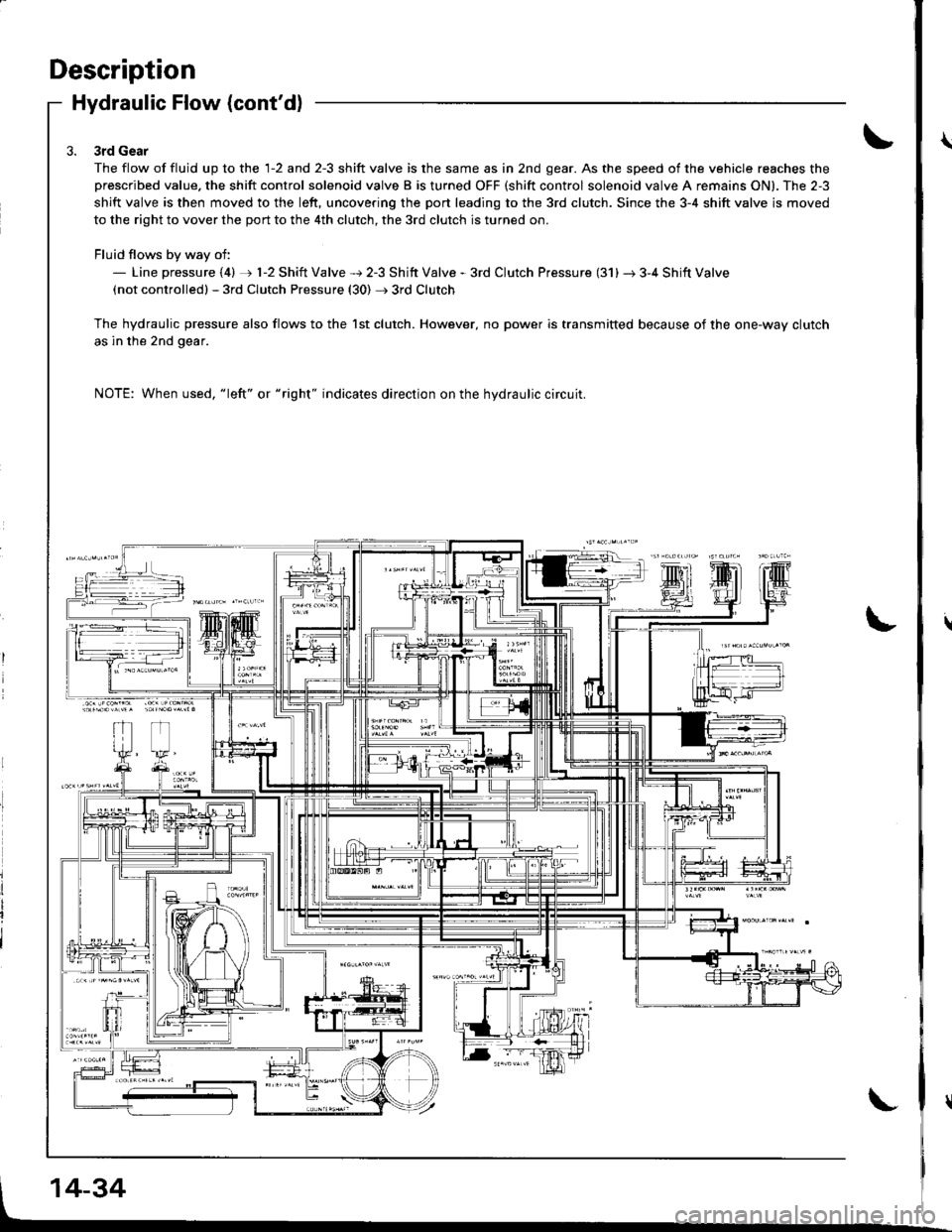
3rd Gear
The flow of fluid up to the 1-2 and 2-3 shift valve is the same as in 2nd gear. As the speed of the vehicle reaches theprescribed value. the shift control solenoid valve B is turned OFF (shift control solenoid valve A remains ON). The 2-3
shift valve is then moved to the left, uncovering the port leading to the 3rd clutch. Since the 3-4 shift valve is moved
to the right to vover the port to the 4th clutch, the 3rd clutch is turned on.
Fluid flows by way of:- Line pressure (4) rj) 1-2 Shift Valve + 2-3 Shift Valve - 3rd Clutch Pressure (31) r 3-4 Shift Valve(not controlledl - 3rd Clutch Pressure (30) + 3rd Clutch
The hydraulic pressure also flows to the lst clutch. However, no power is transmitted because of the one-way clutch
as in the 2nd gear.
NOTE: When used, "|eft" or "right" indicates direction on the hydraulic circuit.
14-34
Page 451 of 1680
Iq1 Position
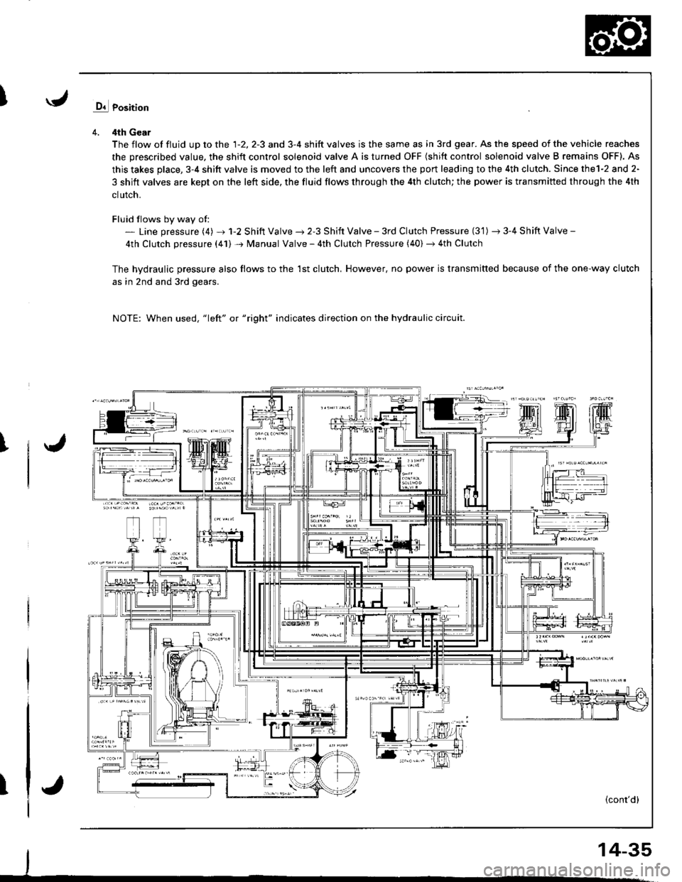
4. 4th Gear
The flow of fluid up to the 1-2, 2-3 and 3-4 shift valves is the same as in 3rd gear. As the speed of the vehicle reaches
the prescribed value, the shift control solenoid valve A is turned OFF (shift control solenoid valve B remains OFF). As
this takes place, 3-4 shitt valve is moved to the left and uncovers the port leading to the 4th clutch. Since thel-2 and 2-
3 shift valves are kept on the left side, the fluid flows through the 4th clutch; the power is transmitted through the 4th
clutch.
Fluid flows by way of:- Line pressure (4) + 1-2 Shift Valve ) 2-3 Shift Valve - 3rd Clutch Pressure (3'1) -t 3-4 Shift Valve -
4th Clutch pressure (41) + Manual Valve - 4th Clutch Pressure (40) + 4th Clutch
The hvdraulic pressure also flows to the 1st clutch, However, no power is transmitted because of the one-way clutch
as in 2nd and 3rd gears.
NOTE: When used, "1eft" or "right" indicates direction on the hydraulic circuit.
I
T(cont'd)
14-35
Page 525 of 1680

L
(t RtcHT sroE covER
@ MAINSHAFT sPEEo sENsoR(O O-RINGS Reptace.
@ couNTERSHAFT spEEo sENsoR
@ HARNESS BRACKET
@ RoLLER
O coLLAR
@ O-RING Replace.
@ FEEo PIPE FLANGE
@ o-RtNG Reptace.
O) SNAP RING
@ 3RD cLUTcH FEED PIPE
@ COUNTERSHAFT LocKNUT (FLANGE NUT) RepIace,
@ couNTERSHAFT CONtcAL spRtNG wAsHER Reptace.
@ PARKING GEAR
G) ONE-WAY cLUTcH
@ COUNTERSHAFT lST GEAR
@ NEEoLE BEARTNG
@ COUNTERSHAFT 1ST GEAR COLLAR
€0 o-RING Reprace.
@ 1sT-HoLD AccUMULAToR ptsTok
@ 1sr-HoLD AccUMULAToR spRtNG
@ o-RING Reptace.
@ rsr-HoLD AccUMULAToR covER
@ SNAP RING
@ PARKING BRAKE PAWL
@ PARKING BRAKE PAWL SPRING
€0 PARKTNG BRAKE PAWL SHAFT
@ PARKTNG BRAKE pawl sroppER
€0 LOCK WASHEF Replace.
@ PARKTNG BRAKE STOP Setecrive oart
@ PARKING BRAKE LEVER
@ PARKING ERAKE LEVER SPRING
@ DowEL PrN
@ o-RlNGs Reptace.
@ RtcHT StOE COVER GASKET Reptace.
@ 1sr cLUTcH FEED ptpE
@ O-R|NGS Reptace.
@ FEEO P|PE GUTOE
TOROUE SPECIFICATIONS
@ SNAP R|NG
@ MAINSHAFT LocKNUT (FLANGE NUT) Replace
@ MAtNSHAFT coNtcAL spRtNG wAsHER Reptace.
@ 1sT clurcH ASSEMBLY
@ O-RINGS Reptace.(4D THRUST wASHEB
@ THRUST NEEDLE EEARING
@) NEEDLE EEARING
@ MAINSHAFT 1sT GEAB
@ MAINSHAFT ,IsT GEAR coLLAR
@ ROLLER
€) coLLAR
@ o-R|NG Reptace.
@ FEED PIPE FLANGE
@ o-RtNG Reptace.
@ SNAP RING
@ 1sT-HoLD cLUTcH FE€D ptpE
@ SUB-SHAFT LOCKNUT TFLANGE NUT) Reptace.
@ suB-SHAFT CONTCAL SpRtNG WASHER Reptace.
@ SUB-SHAFT 1sT GEAR
@ LocK WASHER Reptace.
@ THRoTTLE coNTRoL DRUM
6, THRoTTLE coNTRoL DRUM SPRING
@ OIL SEAL Replace.
@ THRoTTLE coNTRoL cAELE BRAGKET
@ sHtFT coNTRoL soLENoto HARNESS
G0) JOINT BOLT
@ ATF COOLER LINE
@ SEAL|NG wASHERS Reptace.
@ ATF cooLER LINE
@ ATF DrPsflcK
@ JOINT BoLT
@ vEHrcLE SPEED sENsoR
@ o-RING Reptace.
(, DRAIN PLUG
@ SEAL|NG wasHER Replace.
Bolti Nut No.Torque ValueSizeRemarks
5A
6A
6B
8A
12J
18D
r9s
21M
23C
8 N.m (0.8 kgf.m, 6 lbf'ft)
12 N.m (1.2 kgf.m,8.7 lbf.ft)
14 N.m { 1 .4 kgf .m, 1 0 lbf .ft)
22 N'm 12.2 kgf 'm, 16 lbf .ft)
28 N.m (2.9 kgf.m. 2'1 lbl.It)
49 N.m {5.O kgl.m, 36 lbf.tt)
93 N.m (9.5 kgt.m, 69 lbf.tt)
78 N.m (8.0 kgt.m, 58 lbf .ft)
103-O- 103 N.m (1O.5 - O- 10.5 kgf.m.7 5.9 - O- 75.9 tbt.ft)
5xO.8mm
6 x 1.O mm
6 x 1.O mm
8 x 1.25 mm
12x1.25mm
18 x 1.5 mm
19 x 1.25 mm
2t x |.25 mm
23 x 1.25 mm
Joint bolt
Drain plug
Sub-shaft locknut
Mainshaft locknut: Left-hand threads
Countershaft locknut: Left hand
threads
{l
14-109
Page 527 of 1680
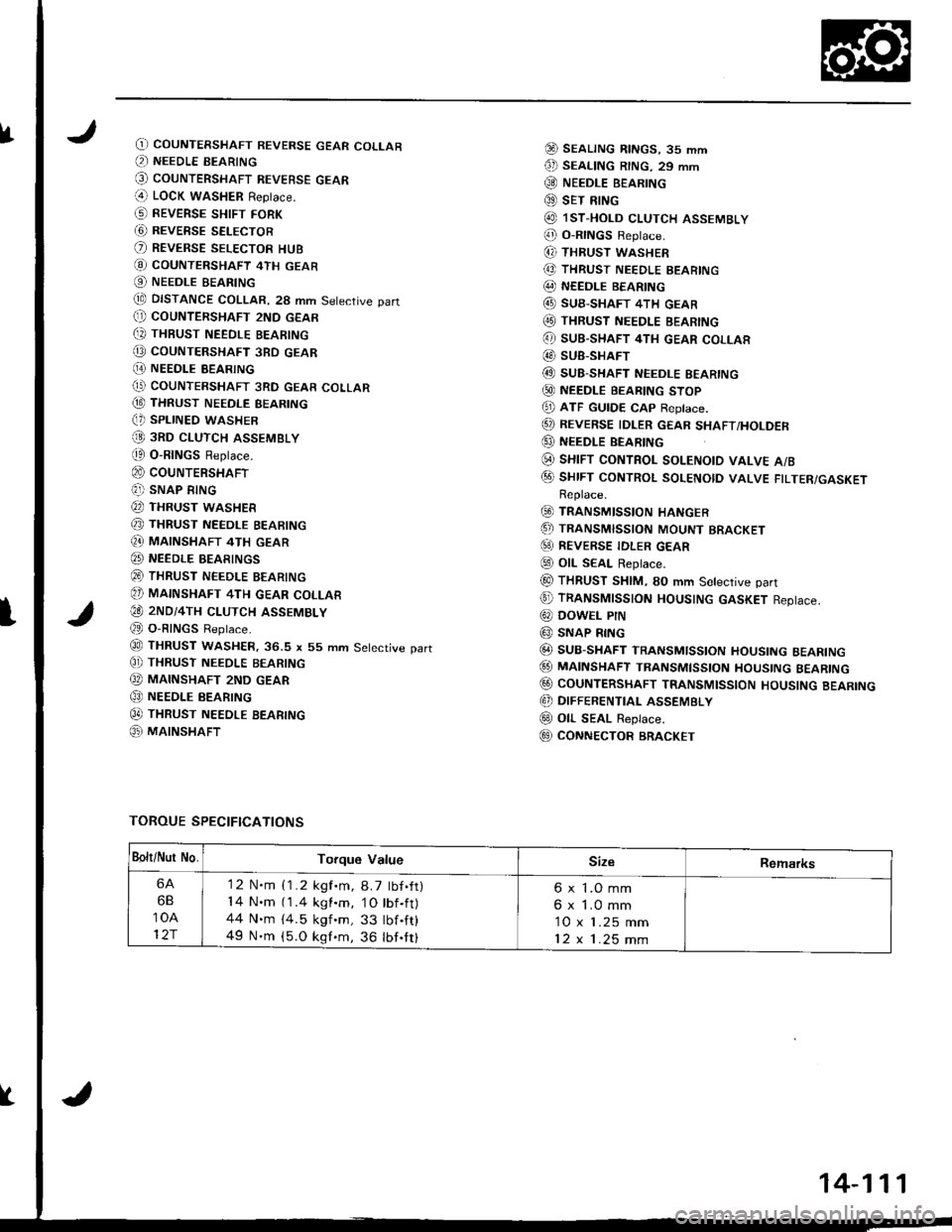
fO) COUNTERSHAFT REVERSE GEAR COLLAR(, NEEDLE BEARING
@ couNTERSHAFT REVEBsE GEAR(4 LOCK waSHER Replace.
G) REVERSE sHtFr FoRK
G) REVERSE SELECTOR
O REVERSE SELEcToR HUB
@ coUNTERSHAFT 4TH GEAR
O NEEDLE BEARING
tE DISTANCE COLLAR, 28 mm Setective part(} COUNTERSHAFT 2ND GEAR
[, THBUST NEEDLE BEARING
@ coUNTERSHAFT 3RD GEAR
[E NEEDI.E BEARING(' COUNTERSHAFT 3RD GEAR COLLAR
@ THRUST NEEDLE BEARING(, SPLINED WASHER
@ 3RD cLUTcH ASSEMBLY
t0 O-RINGS Replace.
@ couNTERSHAFT(?]) SNAP RING
@ THRUST WASHER
@ THRUST NEEDLE BEARING
Q} MAINSHAFT 4TH GEAR
@ NEEDLE BEARINGS
@ THRUST NEEDLE BEARING
@ MAINSHAFT 4TH GEAR coLLAR
€O 2ND/4TH cLUTcH ASSEMBLY
@ O-RINGS Reptace.
@ THRUST WASHER.36.S x 55 mm Setective part
C]) THRUST NEEoLE BEARING
@ MAINSHAFT 2ND GEAR
@ NEEDLE BEARING
0t THRUST NEEDLE BEARTNG
@ MAINSHAFT
@ SEALTNG RtNGs, 35 mm
€D SEAL|NG R|NG. 29 mm
@ NEEDLE B€ARING
@ sET RING
@ lsT.HoLD cLUTCH ASSEMBLY
@ o-RtNGs Reptace.
(, THRUST WASHER
@ THRUST NEEDLE BEARING
@ NEEDLE BEARING
@ SUB-SHAFT 4TH GEAR(O THRUST NEEDLE BEARING
@ sUB-SHAFT 4TH GEAR coLLAR
@ SUB-SHAFT
@ SUB-SHAFT NEEDLE EEARING
@ NEEDLE BEARTNG sToP
@ ATF GUTDE cAp Reptace.
@ REVERSE IDLER GEAR sHAFT/HoLDER
@ NEEDLE BEARING
(i) sHrFT coNTRoL soLENotD vALvE A/B
@ sHrFT coNTRoL soLENotD vALVE FTLTER/GASKETReplace.
@ TRANSMISSIoN HANGER
.5, TRANSMISSIoN MoUNT BRACKET
@) REVERSE TDLER GEAR
@ otL SEAL Replace.
@ THRUST SHIM, SO mm Setective part
@ TRANSMTSSTON HOUSTNG GASKET Reptace.
@ DowEL PtN
@ SNAP RING
@ SUB-SHAFT TRANSMlsstoN HoustNG BEARTNG
@ MA|NSHAFT TRANsMtssroN HoustNG BEARTNG
@ CoUNTERSHAFT TRANSMIssloN HoUsING BEARING
@ DIFFERENTIAL ASSEMBLY
@ oll- SEAL Replace.
E9 CONNECTOR BRACKET
TOROUE SPECIFICATIONS
I
Bolt/Nur No.Torque ValueSizeRemarks
6A
6B
10A
12r
'12 N.m {1.2 kgf.m, 8.7 tbf.ft)14 N.m (1.4 kgl.m, 1O tbf.ft)44 N.m {4.5 kgf 'm, 33 tbf .ft}
49 N.m (5.O kgf.m, 36 lbf.tt)
6 x 1.O mm
6 x 1.0 mm
10 x 1.25 mm
12x1.25mm
14-111
Page 529 of 1680
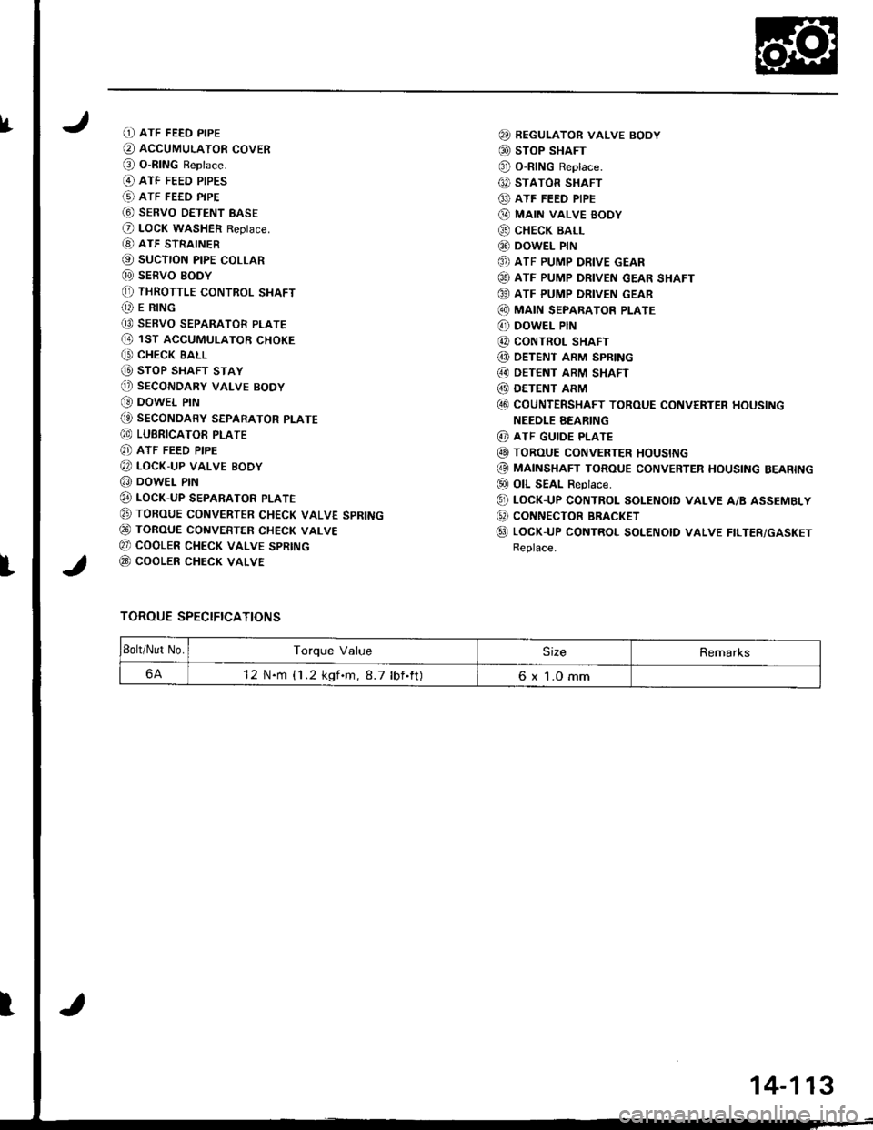
IfD ATF FEED PIPE
O AccUMULAToR covER
@ o-RING Reptace.(O ATF FEED PIPES
(!) ATF FEED PIPE
@ sERvo DETENT BASE
O LocK WASHER Reptace.
[8) ATF STRAINER
@ sucTroN ptpE coLLAR
@ sERVO EODY(, THRoTTLE coNTRoL SHAFT(t E R|NG
Q9 SERVO SEPARATOR PLATE(D 1ST ACCUMULAToR cHoKE
C' CHECK EALL
@ sToP SHAFT STAY
@) SECONDARY VALVE BODY
OO DOWEL PIN
(t SEcoNDARY SEPARAToR PLATE
@ LUBRICAToR PTATE
8] ATF FEED PIPE
@ LocK-uP vALvE BoDy
@ DowEL PrN
@ LocK-uP SEPARAToR PLATE
E TORoUE CoNVERTER cHEcK VALVE SPRING
€0 ToRouE CoNVERTER cHEcK vALvE
Q) COOLER CHECK VALVE SPRING
@ cooLER cHEcK VALVE
TOROUE SPECIFICATIONS
@ REGULAToR vALvE BoDY
@ sToP SHAFT
@ o-RING Reptace.
6, STATOR SHAFT
@ ATF FEED PIPE
@ MA|N VALVE BOOY
@ cHEcK BALL
@ DowEL PrN
@ ATF PUMP DRIVE GEAR
@ ATF PUMP DRIVEN GEAR SHAFT
OO ATF PUMP DRIVEN GEAR
@ MA|N SEPARAToR PLATE
6' DowEL PIN
@ CONTROL SHAFT
@ DETENT ARM SPRING
@ OETENT ARM SHAFT
@ DETENT ARM
@ coUNTERSHAFT ToRoUE coNVERTER HoUSING
NEEOLE BEARING
@ ATF GUIDE PLATE
@ ToRouE coNvERTER HoustNG
@ MAINSHAFT ToRoUE coNvERTER HousING BEARING
@ oll SEAL ReDtace.
@ LocK-up coNTRoL soLENotD vALvE A/B ASSEMBLy
@ coNNEcToR BRACKET
@ LocK-UP coNTRoL SoLENoID vALvE FILTER/GASKET
Replace.
Bolt/Nut No.Torque ValueSizeRemarks
6A12 N.m {1 .2 kgf.m,8.7 lbf.ft)6 x 1.0 mm
I
14-113
Page 613 of 1680

Differential
Ted Roll
(B18C1
er Bearinr
engine)
Preload Adjustment (cont'd)aperelng
7. lf the tapered roller bearing preload is not within the
standard, select the 79.5 mm shim from the follow-
ing table which will give the tapered roller bearing
preload closest to the standard mean value o{ 2.50
N.m (25.5 kgt.cm, 22 lbf.in).
NOTE: Changing the 79.5 mm shim to the next size
will increase or decrease tapered roller bearing
preload about O.3-0.4 N.m (3-4 kgl.cm,
2.6 - 3.5 lbf.in).
79.5 mm SHIM
Part NumberThickness
41460-PsD-0000.66 mm (0.0260 in)
AB41461 - P5D - 0001.17 mm (0.0461 in)
AC41462-PsD-0001.20 mm (0.0472 in)
AD41463-P5D-0001.23 mm (0.0484 in)
AE41464-PsD-000'1.26 mm (0.0496 in)
AF41465-PsD-0001.29 mm (0.0508 in)
AG41466-PsD-0001.32 mm (0.0520 in)
AH41467-PsD-0001.35 mm 10.0531 in)
AI41468-PsD-0001.38 mm (0.0543 in)
41469-P5D-0001.41 mm (0.0555 inl
AK41470-PsD-0001.44 mm (0.0567 in)
AL41471 - PsD - 000'1.47 mm {0.0579 in}
41472-P5D-0001.50 mm (0.0591 in)
AN41473-PsD-0001.53 mm {0.0602 in}
AO41474-P50-0001.56 mm (0.0614 in)
AP41475-PsD-0001.59 mm (0.0626 in)
AO41476-P5D-000'1.62 mm {0.0638 in}
AR41477-P5D-0001.65 mm (0.0650 in)
41478-P5D-0001.68 mm (0.0661 in)
41479-P50-0001.71 mm (0.0673 in)
AU41480-PsD-0001.74 mm (0.0685 in)
41481 - PsD - 000'1.77 mm (0.0697 in)
41482-PsD-000'1.80 mm (0.0709 in)
AX41483-P5D-0001.83 mm (0.0720 in)
8. Recheck the tapered roller bearing preload.
9. How to select the correct 79.5 mm shim:
1) Compare the tapered roller bearing preload you
get with the 79.5 mm shim that was removed
with the soecified mean Dreload of 2.50 N'm
(25.5 kgf .cm, 22 lbf.in).- 2l ll vour measured tapered roller bearing preload
is less than specified, subtract your's from the
specitied.
lf vour's is more than specitied, subtract the
soecified from vour measurement.
For example with a 1.38 mm {0.0543 in) shim:
@ specified 2.50 N.m (25.5 kgf.cm, 22 lbl.in)- you measure 0.54 N.m (5.5 kg{.cm, 5lbl.in}
2.0 N.m (20 kgf.cm, 18lbf.in) less
@you measure 3.29 N.m (33.5 kgI.cm, 29 lbt.in)- specified 2.50 N.m (25.5 kgf.cm, 22 lbf.in)
0.8 N.m (8 kgf.cm,7lbf.in) more
-3) Each shim size up or down from standard
makes about O.3-0.4 N.nt (3-4 kgf.cm,
2.6-3.5 lbl.in) difterence in tapered roller
bearing preload.
a In example @, your measured tapered roller
bearing preload was 2.O N.m (2O kgt.cm,
18 lbf in) less than standard so you need a
79.5 mm shim live sizes thicker than stan-
dard {try the 1.53 mm (O.0602 in) shim and
recheck).
a ln example @ your's was 0.8 N.m {8
kgf.cm,7lbf.in) more than standard. so
you need a thrust shim two sizes thinner (try
the 1 .32 mm (O.O52O in) shim and recheck).
1O. After adjusting the tapered roller bearing preload, as-
semble the transmission, and installthe lransmission
housing (see section 13).
8 x 1.25 mm
27 N,m (2.8 kgt'm, 20 lbf.ft)
11. Rotate the difterential assembly in both directions
to seat the tapered roller bearings.
1 5-16
\
Page 622 of 1680

Limited Slip Differential (B18C5 engine)
Tapered Roller Bearing Preload Adiustment (cont'd)
7. lf the tapered roller bearing preload is not within the
standard, select the 79.5 mm shim from the follow-
ing table which will give the tapered roller bearing
preload closest to the standard value of 2.50 N'm
(25.5 kgicm, 22 lbf in). Changing the 79.5 mm shim
to the next size will increase or decrease tapered
roller bearing preload about 0.3 - 0.4 N'm (3 - 4
kgl.cm, 2.6 - 3.5 lbf.in).
79.5 mm SHIM
Part NumberThickness
41460-PsD-0000.66 mm (0.0260 in)
A841461 - P5D - 0001.17 mm (0.0461 in)
AC41462-P5D-0001.20 mm (0.0472 in)
AD41463-P5D-0001.23 mm (0.0484 in)
AE41464-P5D-0001.26 mm (0.0496 in)
AF41465-P5D-0001.29 mm (0.0508 in)
41466-PsD-0001.32 mm (0.0520 in)
AH41467-PsD-0001.35 mm (0.0531 in)
AI41468-P5D-0001.38 mm (0.0543 in)
AJ41469-PsD-0001.41 mm (0.0555 in)
AK41470-PsD-0001.44 mm (0.0567 in)
AL41471 - PsD - 0001.47 mm (0.0579 inl
41472-P5D-0001.50 mm (0.0591 in)
AN41473-P5D-0001.53 mm (0.0602 in)
AO41474-PsD-0001.56 mm (0.0614 in)
AP41475-P5D-0001.59 mm (0.0626 in)
AO41476-P5D-0001.62 mm (0.0638 in)
AR41477-P5D-0001.65 mm (0.0650 in)
AS41478-PsD-0001.68 mm (0.0661 in)
AT41479-P5D-0001.71 mm (0.0673 in)
AU41480-PsD-0001.74 mm (0.0685 in)
41481 - PsD - 0001.77 mm (0.0697 in)
41482-P5D-000'1.80 mm (0.0709 in)
AX41483-P5D-0001.83 mm (0.0720 in)
15-26
\
8. How to select the correct 79,5 mm shim:-1) Compare the tapered roller bearing preload you
get with the 79.5 mm shim that was removed
with the sDecified preload of 2.50 N'm (25.5
kgf.cm, 22 lbf.in).-2) lf vour measured tapered roller bearing preload
is less than specified, subtract your's from the
sDecified.
lf your's is more than specified, subtract the
specified from your measurement.
For example with a 1.38 mm (0.0543 in) shim:
@ specified 2.50 N.m (25.5 kgf.cm,22 lbiin)- you measure 0.54 N.m (5.5 kgf'cm, 5 lbf in)
2.0 N.m (20 kgf.cm, 18 lbf.in) less
@ you measure 3.29 N.m (33.5 kgf.cm, 29 lbf in)
- specified 2.50 N'm (25.5 kgf'cm, 22 lbf in)
0.8 N.m {8 kgf.cm. 7 lbf in) more
-3) Each shim size up or down from standard
makes about 0.3 - 0,4 N.m (3 - 4 kgf'cm,
2.6 - 3.5 lbf.in) difference in tapered roller
bearing preload.
o In example @, your measured tapered roller
bearing preload was 2.0 N.m (20 kgf.cm,
18 lbf.in) less than standard so you need a
79.5 mm shim five sizes thicker than stan-
dard (try the 1.53 mm (0.0602 in) shim and
recheck).
. In example @, your's was 0.8 N.m (8
kgf.cm,7 lbf.in) more than standard, so you
need a thrust shim two sizes thinner (try
the 1.32 mm {0.0520 in) shim and recheck).
Recheck the tapered roller bearing preload.
After adjusting the tapered roller bearing preload,
assemble the transmission, and install the transmis-
sion housing.
Rotate the difterential assembly in both directions
to seat the tapered roller bearings.
10.
11.
Page 656 of 1680
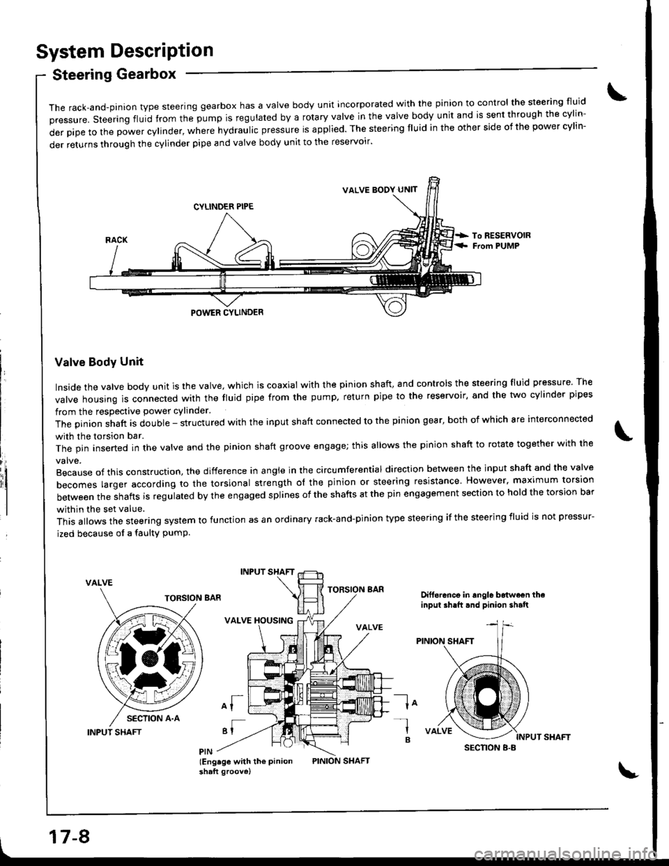
System DescriPtion
Steering Gearbox
it
The rack,and-pinion type steering gearbox has a Valve body unit incorporated with the pinion to control the steering fluid
pressure. steering fluid from the pump is regulated by a rotary valve in the valve body unit and is sent through the cylin-
derpipetothepowercy|inder,wherehydrauIicpressureisapp|ied.Thesteeringf|Uidintheothersideofthepowercy|in-
der returns through the cylinder pipe and valve body unit to the reservoir'
Valve Body Unit
Inside the valve body unit is the valve, which is coaxial with the pinion shaft, and controls the steering fluid pressure The
valve housing ls connected wirh the fluid pipe from the pump. return pipe to the reservoir, and the two cylinder pipes
from the respective power cylinder.
The pinion shaft is double - structured with the input shaft connected to the pinion gear, both of which are interconnected
with the torsion bar.
The pin inserted in the valve and the pinion shaft groove engage; this allows the pinion shaft to rotate together with the
Because of this construction. the difference in angle in the circumferential direction between the input shaft and the valve
becomes larger according ro the torsional strength ol the pinion or steering resistance. However. maximum torsion
between the shafts is regulated by the engaged splines of the shafts at the pin engagement section to hold the torsion bar
within the set value.
This allows the steering system to function as an ordinary rack-and-pinion type steering if the steering iluid is not pressur-
ized because of a faulty PumP.
VALVE
INPUT SHAFT
INPUT SHAFT
VALVE XOUSING
of
'I
lEng.ge with th€ Pinionshaft groove)
TORSION BARDift6rance in angle b6twe€n theinput ih.ft.nd pinion shalt
la-l
B
VALVE BODY UN]T
SECNON B.B
17-8