Page 470 of 1680

Diagnostic
Trouble Code(Drc)*
,94
lndicator
Light
SymptomPossible CauseRefer to
Page
P1153(1)Blin ks
Lock-up clutch does not engage,
Lock-up clutch does not disen-
gage.
Disconnected lock-up control solenoid
valve A connector
Short or open in lock-uP control
solenoid valve A wire
Faulty lock-up control solenoid valve A
14-56
P1758
t2lBlinks
. Lock-up clutch does not engage.Disconnected lock-up control solenoid
valve B connector
Short or open in lock-uP control
solenoid valve B wire
Faulty lock-up control solenoid valve B
14-58
P1790(3)Blinks
. Lock-up clutch does not engage.Disconnected throttle position (TP)
sensor connector
Short or open in TP seflsor wire
Faulty TP sensor
14-60
P1191(4)Blinks
. Lock-up clutch does not engage.Disconnected vehicle speed sensor
{VSS} connector
Shon or open in VSS wire
Faulty VSS
14-61
P1705
(5)Blinks
. Fails to shift other than 2nd - 4th
gears.
. Lock-up clutch does not engage.
. Shod in AvT gear position switch wire
. Faulty A,/T gear position switch14-62
P1706(6)OFF
' Fails to shift other than 2nd -
3rd - 4th gears.
. Lock-up clutch does not engage.
Disconnected A/T gear position switch
connector
Open in A/f gear position switch wire
Faulty A/f gear position switch
14-64
P0753
(71Blinks
. Fails to shift (between 1st - 4th
or 2nd - 3rd gear only).. Fails to shift (stuck in 4th gear).
Disconnected shift control solenoid
valve A connector
Short or open in shift control solenoid
valve A wire
Faulty shift control solenoid valve A
14-66
P0758(8)Blinks
. Fails to shift (stuck in 1st or 4th
gears).
Disconnected shift control solenoid
valve B connector
Short or open in shift control solenoid
valve B wire
Faulty shift control solenoid valve B
14-68
P0120(9)Blin ks
Lock-up clutch does not engage.Disconnected countershaft speed sen-
sor connector
Short or open in countershaft speed
sensor wrre
Faulty countershaft speed sensor
1+10
P1192
00)Blinks
. Lock-up clutch does not engage,Disconnected engine coolant tempera-
ture (ECT) sensor connector
Short or open in ECT sensor wire
Faulty ECT sensor
14-72
P0725
{1 1)OFF
Lock-up clutch does not engage.Disconnected ignition coil connector
Short or open in ignition coil wire
Faulty ignition coil
14-73
Symptom-to-ComPonent Chart
Electrical System
(DTC)*: The DTCS in the parentheses are the codes the E indicator light indicates {blinks) when the service check connec-
tor is connected to the special tool (SCS service connector)
4-54
Page 472 of 1680

Electrical Troubleshooting
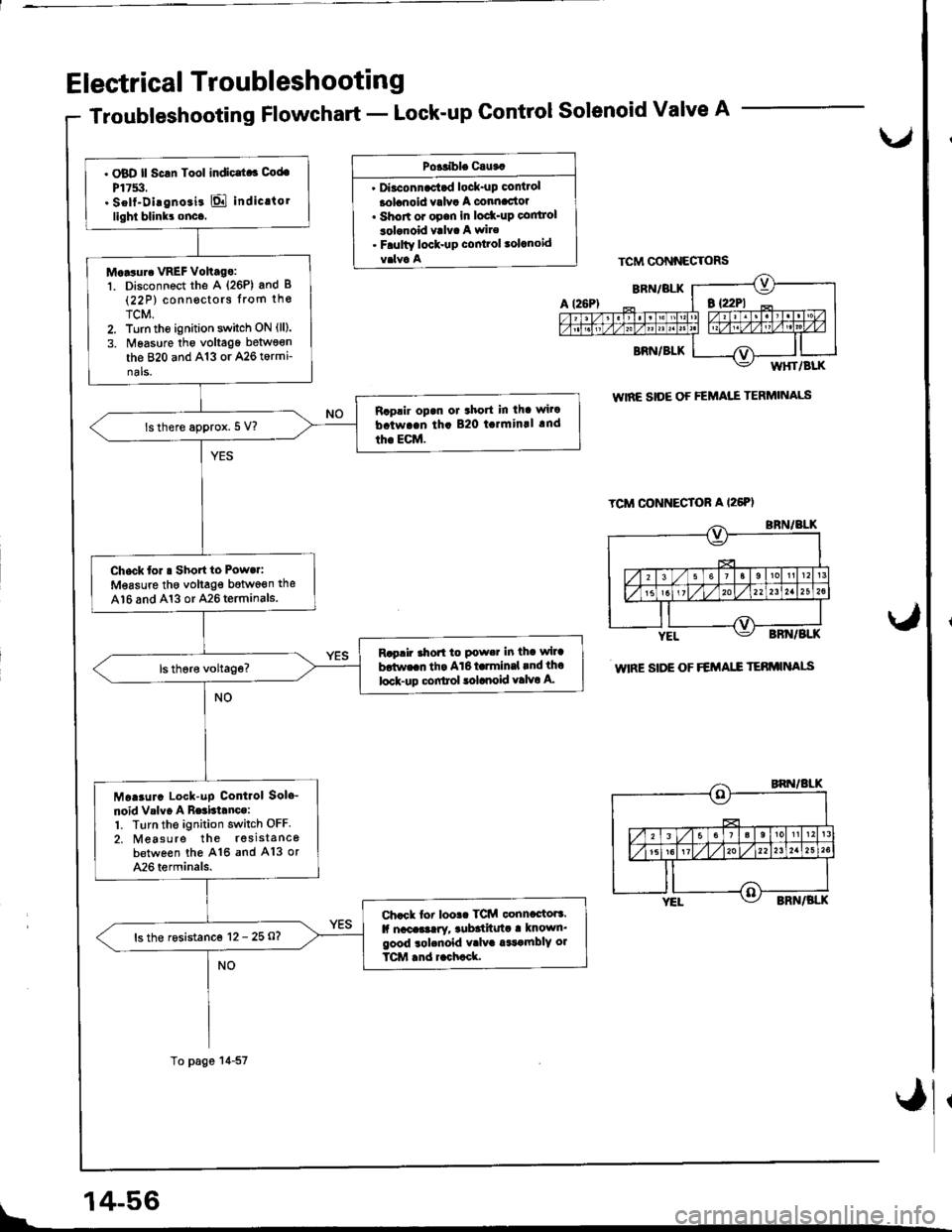
Troubleshooting Flowchart - Lock-up Control Solenoid Valve A
Po+tible Cauta
' Diaconnac'tad lock-up control
lolanoid valva A connac'toa. Shon or opan in lod(-up co|ltrol
3olonoid valva A wire. Faulty lock-up cont?ol lolanoid
TCM CONNECTORS
WIRE SIOE OF FEMAI."E TERMINALS
WIRE SIDE OF FEMA.E TEBMINAIS
L/
. OBD ll Scrn Tool indic|t.3 Cod.
P17!i:t.. Self-Dirgnoii! E indic.torlight blinkr onco.
M.Nur. VREF Voh.go:'t. Disconnect the A (26P) and B(22 P) conn€ctors lrom th€
TCM.2. Turn tho ignition switch ON (ll).
3. Nleasure tho voltage betwson
the 820 and A13 or A26 tormi-nals.
Raplir opan or 3hort in tha wi.a
b.twa.n th. B20 t.lmin!l .nd
th€ EcM.lsthere approx. 5 V?
Check tor a Short to Powa.i
Measure tho voltag€ botwoen the
A16 and A13 or A26 terminals.
Rap!fu ahorl to Pow.t in tha wlra
b!tw..n th. A16 t rmln.l rnd tho
lock-up c!filtol lolaooid valvo A.
Moaaurc Lock-uP Contlol Sole-
noid Vrlvo A Be3bianco:1. Ttrrn the ignition switch OFF.
2. Measure the rssistancebetween the A16 and A13 or
A26 terminals.
Chack tor loolc TCM conncctora.lf naca!3!ry, rub3tftuta a known'good rolcnold v.lva a$amblY ol
TCM .nd r.ch.ck.
ls the rosistanco 12 - 25 O?
To page 14-57
\
14-56
Page 474 of 1680

Electrical Troubleshooti n g
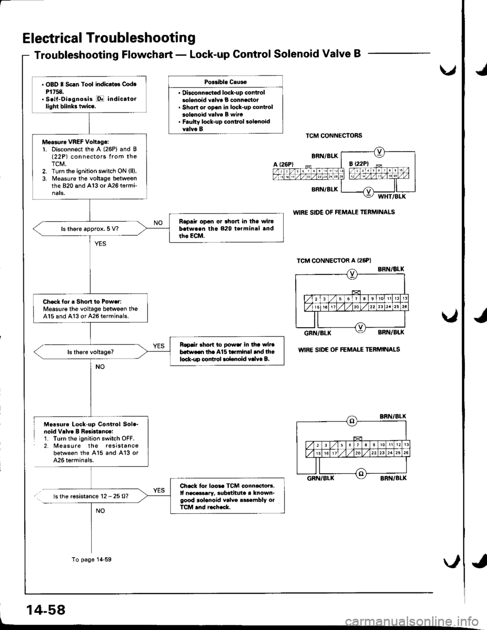
Troubleshooting Flowchart - Lock-up Control Solenoid Valve B
Poitibl. Cau3o
. Dbconn.stsd lock-up controlsolenoid valv6 B connectol. Short or open in lock-up cont.ol3olonoid valva B wiro. Faulty lock-up conttol solcnoidvalva BTCM CONNECTORS
WIRE SIDE OF FEMALE TERMINALS
wlRE SIDE OF FEMAIE TERMINALS
Moa3ure Lock-up Control Sol.-noid Vrlv. B R$btanco:1. Turn the ignition switch OFF.2. Measure the reslstancebotween the A15 and A13 or426 terminals.
.. ls the r€sistance 12 -25A?
14-58
u,
NO
. OBD ll Scrn Tool indicrt.3 Cod.P1758.. Self-Oiagnosis E indicato.light blink3 twics.
Moasuro VREF Vohago:1. Disconnect the A (26P) and B(22P) connectors from theTCM.2. Turn the ignition switch ON (ll).
3. Measure tho voltage betweenthe 820 and A13 or 426 termi-nats.
Rapair opan or lhort in iho wirobatwaan tho 820 terminal andth. ECM.ls there approx. 5 V?
Check for a Shon to Powar:Measure the voltage between th€A15 and A13 or A26 terminals.
Rapair .hort to powar in tha wircbatr.,aon tha A15 ta.mlnal and thalock.up control rol.noid valva B.
Chack for loo.. TCM connactoB.It necassrry, 3ub3thuta ! known-good 3olcnoid valve .ir€mbly olTCM .nd r6ch.ck.
To page 14-59
*d
*,
Page 482 of 1680

Electrical Troubleshootin g
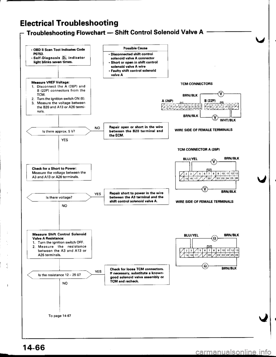
Troubleshooting Flowchart - Shift Gontrol Solenoid Valve A
,
Possiblc Cause
. Dbconnoctod shift controlsolonoid vrlv€ A conneclot. Short or oDen in 3hift controlsolenoid valve A wire. Faulw 3hift control solanoid
Morsure VREF Vohag6:1. Disconnect the A (26P) andB (22P) connectors trom theTCM,2. Turn the ignition switch ON (ll).
3. Measure the voltage betweenthe 820 and A13 or 426 termi-nals.
TCM CONNECTORS
WIRE SIDE OF FEMALE TERMINALS
WIRE SIDE OF FEMALE TERMINALS
14-66
TCM CONNECTOR A (26PI
. OBD ll Scan Tool Indicat . Codem7$.. Self-Diagnosis E indicatorligln blinb sovon times.
Repair open or 3hort in the wirobetwoon tho 820 terminal 3nd
the ECM.ls there approx. 5 V?
Chock lol a Short to Power:Measure the voltage between the
43 and Al3 or 426terminals.
Repail short to powgr in the wirebelwoon the A3 termin.l and th6shift control solonoid valvo A.
Measure Shift Contlol SolenoidValvo A R63btenc.:1. Turn the ignition switch OFF.2. Measure the resista ncebetween the 43 and A13 or426 torminals.
Chock for loo3. TCM connectors.ll nec€ssary, 3ubsthute a known-good solenoid v.lve sssombly orTCM and r6check.
ls the resistance 12 - 25 O?
To page 14-67
Page 483 of 1680
From pege 14-66
Chock Shitt Control SolonoidValvo Alor a Short Circuit:1. Disconnect the 3P connectortrom lhe shift control solenoidvalve assembly,2. Check lor continuity betwoenthe A3 and A13 or A26 termi-nals,
Rapair sho.t to ground in thswi.c batwocn tha A3 torminalind th6 shift control 3olanoid
Mearur. Shitt Control Sol.noidValv. A Re3istsnce at th. Sol€-noid Connactor:Measur€ the rosistance betweenterminal No. 1 of the shift controlsolenoid connector and bodyoround.
Chcck tor ooen in th6 wir6betwocn the A3 tclminll .nd tho.hift control 3ol6noid vrlvo A.ls the rosistsnce 12 - 25 0?
Repl.c6 th. .hltt control .016-noid valvo aarcmbly.
TCM CONNECTOR A I26PI
WIRE SIDE OF FEMALE TERMINALS
SHIFT CONTROL SOLENOID
CONNECTOR
Ll /i3 tL
ar-urvelf-
@
IL--
TERMINAL SIDE OF MALE TERMINALS
14-67
Page 484 of 1680

Electrical Troubleshootin g
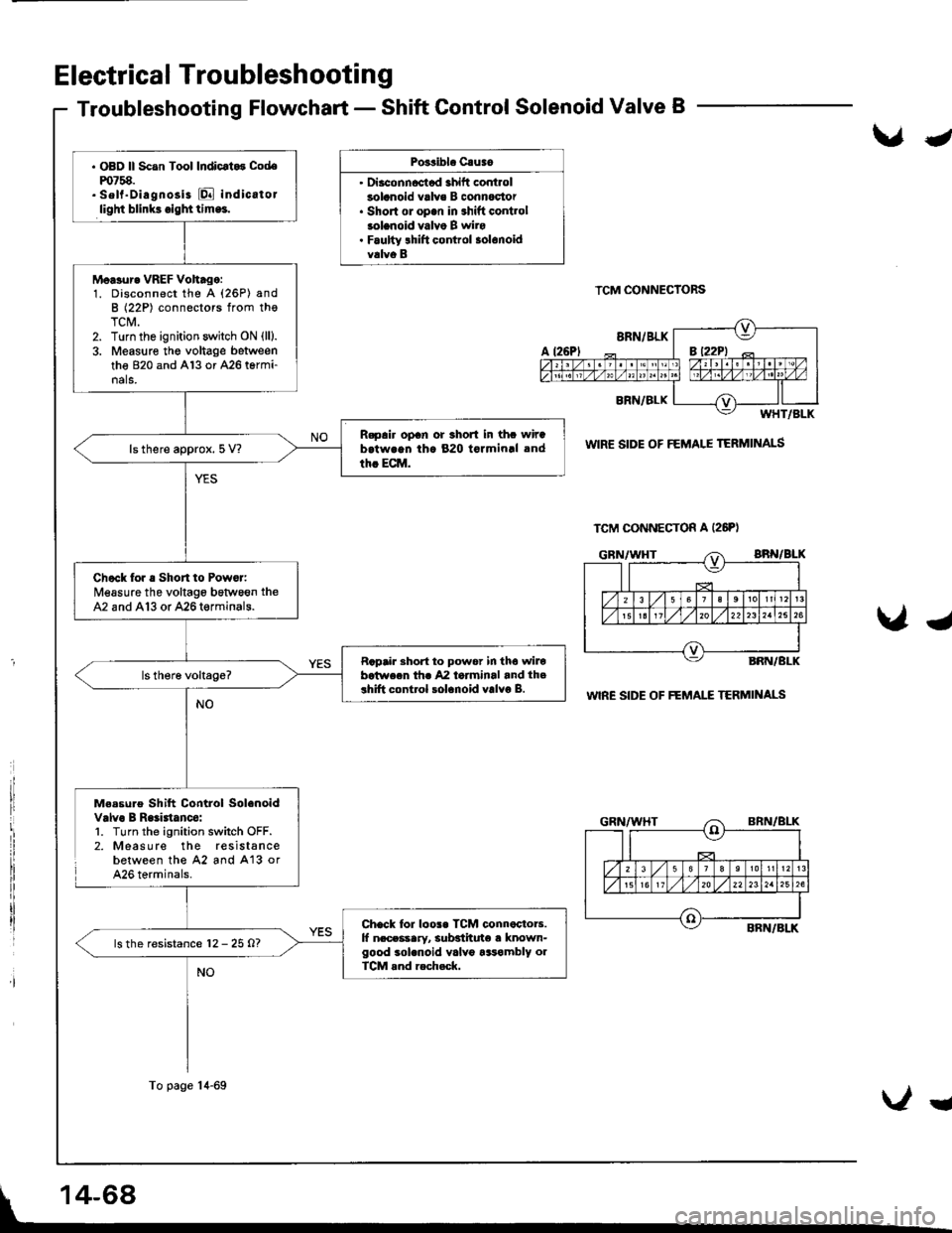
Troubleshooting Flowchart - Shift Control Solenoid Valve B
Po3sibl. Cauao
' Diaconncctad ahift controlsolanoid valve B connoc'tor. Short ol op.n in shift contlolsolanoid valvo B wiro. Faulty lhift control solonoidvalvo B
TCM CONNECTORS
WIR€ SIDE OF FEMALE TERMINALS
WIRE SIDE OF FEMAI."E TERMII{ALS
Me.sure Shift Control Solenoidvalvo B Raliatanco:l. Turn the ignition switch OFF.2. Measure the resistancebetween the 42 and A'13 orA26 terminals.
J
Ug
TCM CONNECTON A (26PI
. OBD ll Scan Tool Indicrt.3 Codem758.. sell"Diagnosi3 [Q indicatorlight blink3.igl|ttlm.!.
Moasur. VREF Voh.go:1. Disconnect the A (26P) andB (22P) connectors from thoTCM.2. Turn the ignition switch ON (lll.
3. Measure the voltage betweenthe 820 and Al3 or A26 termi-nals.
R.pair opan or 3hort in thc wirab.twrqn th. 820 tormin.l and
th. ECM.ls there approx. 5 V?
Check for . Short to Powor:Measure the voltage bstween theA2 and A13 or 426termin8ls.
Rapair Bhort to power in tho wilobotwecn thr 42 laiminal and th.3hift control solanoid valvo B.
Chack lor loos. TCM connactoB.lf n.ceasary, subsiituto a known-good sol.noid valv6 tasambly olTCM rnd rech.ck.
ls the resistance 12 - 25 O?
To page 14-69
Ug
Page 485 of 1680
u
From pag€ 14-68
Chock Shitt Control Sol.noidV.lv! B tor r Short Circuit:1. Disconngct th6 3P connoctortrom the shift control solenoidvalve sssombly.2. Check for continuitv betwo€nth€ A2 and 413 or 426 tormi-nals.
Rapalr lhort to ground in ihowirc batwoan lhc A2 tarminaland th6 ihlft control 30lcnoidvalva B.
M...ur. Shift Control Sol.noidValv. B R.rid.[c. rt tha Sol.-noid Connactor:Measure the resistanc6 betweenterminal No, 3 of th€ shitt controlsolenoid connector and bodyground,
Ch.ck for open in lh. wi..batwaon th6 42 torminrl rnd thoahitt control lolanoid valva B.
ls the resistance l2 - 25 0?
TCM CONNECTON A I26PI
WIRE SIDE OF FEMALE TERMINALS
SHIFT CONTROL SOLENOIDCONN€CTOR
GRN/WHT
TERMINAL SIDE OF MALE TERMINALS
14-69
Page 496 of 1680

Electrical Troubleshootin g
Troubleshooting Flowchart - LC Control System
\.r.Poeribl. C.ua.
control
NOTE: Do not continue with this troubleshootingot any other DTCS have beeo corrected.until thg caus€s
v
t,
I
'I
14-80
Chock lor Anothor Cod6:Check whether the OBD lltool indicates another codo.
P6rform tha TroublorhootingFlowcha for tho indicrladCodolsl.R.ch.ck fof codo P0740 !ft.tt.oublo3hooting.
Does the OBD ll scan tool indi-cate another code?
Tost Line Proisurg:Measure the line pressure (see
pag6 14-98).
R.prir tho hydraulic syltcm !!n.cGsary (soc pago 1+98).ls the line prsssure within theservic€ limit?
Repl!c6 th6 Lock-up ControlSolenoid Velva As3ambly .ndRschock:1. Replace the lock-up controlsolenoid valve y'y'B assembly(see page '!4-87).
2. Turn the ignition switch OFFand reset the TCM memoryby removing the BACK UPfuse in the und€r-hood fuse/rolay box tor more than 10seconos.3. Using the OBD ll scan tool,check that the engine coolanttemperatures is 176'F (80'C)
4. Drive the vehicle at 55 mph(88 km/h) constantly lor rnorethan one mrnute,5. Recheck for code P0740.
Does the OBD ll scan tool indi-cate codo P0740?Tha iy3t6m ir OK .t thi! timc.
V
I
J