Page 438 of 1680
Description
Electronic Control System (cont'd)
Circuit Diagram and Terminal Locations
IGNITIONSWITCH
LOC(-UPCONTFOL
LOCK - UP COIITBOLSOLENOIO VALVE B
SHIFI CONTROLSOLENOID VALVE A
sHrFtc0NtRotSOLENOIDVALVES
€cT
SAFOS S
AT CHK
ACCt
scs
LG1
LG1
NMSG
NC
NCSG
vcc2
TPS
sG2
ECT
BAios s
AT CNI(
ACCt
LG1
LG2
257I10112356789lo
151620222324252612l417lg20
14-22
r
{
Page 439 of 1680
The valve bodies include the main valve body, the secondary valve body, the regulator valve body, the servo body andthe lock-up valve bodv.
The ATF pump is driven by splines behind the torque converter which is attached to the engine, Fluid {lows through
the regulator valve to maintain specified pressure through the main valve body to the manual valve, directing pressure
to each of the clutches.
SHIFT CONTROL SOLENOIDVALVE ASSEMBLY
RIGHT SIDE COVER
LOCK'UP VALVE BODYSERVO BODY
SECONDARY VALVEBODY
VALVE BODY
REGULATOR VBODY
LOCK-UPOIL PUMP GEARS
SOLENOID VALVEASSEMBLYTOROUEHOUSING
{cont'd)
%<->--::/ )C)
IrY,
14_23
'
Page 440 of 1680
Description
Hydraulic Control (cont'd)
Regulator Valve Body
The regulator valve body is located on the main valve body. The regulator valve body consists of the regulator valve,
the torque converter check valve, the cooler check valve, and the lock-up control valve.
LOCK.UP CONTROL VALVE
Lock-up Valve Body
The lock-up valve body with the lock-up shift valve and lock-up timing B valve is located on the regulator valve body.
LOCK-UP SHIFY VALVE
TIMI[\'G B VALVE
REGUI-ATOR VALVE
COOLER CHECK VALVE
Page 441 of 1680

I
I
Rogulator Valve
The regulator valve maintains a constant hydraulic pressure from the ATF pump to the hydraulic control system. while
also furnishing fluid to the lubricating system and torque converter.
Fluid flows through B and B'. The fluid enters through B and flows through the valve orifice to A, pushing the regulator
valve to the right. According to the level of hydralic pressure through B. the position of the valv€ changes, and the
amount of the fluid through D from B' thus changes. This operation is continued, maintaining the line pressure.
NOTE: When used, "left" or "right" indicates direction on the illustration below.
{ENGINE NOT RUNNINGI{ENGINE RUNNINGI
STATOR SHAFT
Stator Reactior Hydrrulic Prcsrure Control
Hydraulic pressure incresse, according to torque, is performed by the regulator valve using stator torque reaction. The
stator shaft is splined to the stator and its arm end contacts the regulator spring cap. When the vehicle is accelerating or
climbing (Torque Converter Range), stator torque reaction acts on the stator shaft and the stator shaft arm pushes the reg-
ulator spring c8p in the direction of the srrow in proportion to the reaction. The spring compresses and the regulator valve
moves to incrsase the regulated conlrol pressure or line pressure. Line pressure is maximum when the stator reaction is
maximum.
TOR VALVE
{cont'dl
From ATF PUMP
I
STATOB SHAFTSTATOR SHAFT ARM
14-25
Page 442 of 1680
Description
Hydraulic Control (cont'dl
Main Valve Body
The main valve body hous€s the manual valve, the 1 2 shift valve, the 2-3 shilt valve, the 4th exhaust valve, the CPC
valve, and the reliel valve.
The primary {unctions of this valve body are switching ATF passages on and olf, and controlling the hydraulic pressure
going to the hydraulic control system.
4TH EXHAUST VALVE2-3 SHIFT VALVECPC VALVE
RELIEF VAI-VE
MANUAL VALVE
MAIN VALVE EODY
Secondary Valve Body
The secondary valve body is located on the main valve body. The secondary valve body houses the 3-2 kick-down valve,
the 4-3 kick-down valve, the 2-3 orifice control valve, the orifice control valve. the 3-4 shitt valve, the modulator valve,
and the servo control valve.
ORIFICE CONTROLVALVE2-3 oRtFtCE CONTROT_ VALVE
3-4 SHIFT VALVE
1-2 SHIFT VALVE
MOOULACONTROL VALVE
Page 443 of 1680
Servo Body
The servo body is located on the secondary valve body.
The servo body houses the servo valve (integrated with the shift fork shaft), the throttle valve B, and the accumulator pis-
tons.
THROTTLE
Accumulator Pistons
The accumulator pistons are assembled in the servo body and right side cover. The 1st-hold clutch accumulator piston is
in the right side cover, and the 1st,2nd,3rd, and 4th accumulator pistons are in the servo bodv.
lST.HOLD ACCUMULATORPISTON
lST ACCUMUI.ATOR
2ND ACCUMULA3RO ACCUMULATOR PISTON
THBOTTLE LONG VALVE
RIGHT SIDE COVER
14-27
Page 444 of 1680

Description
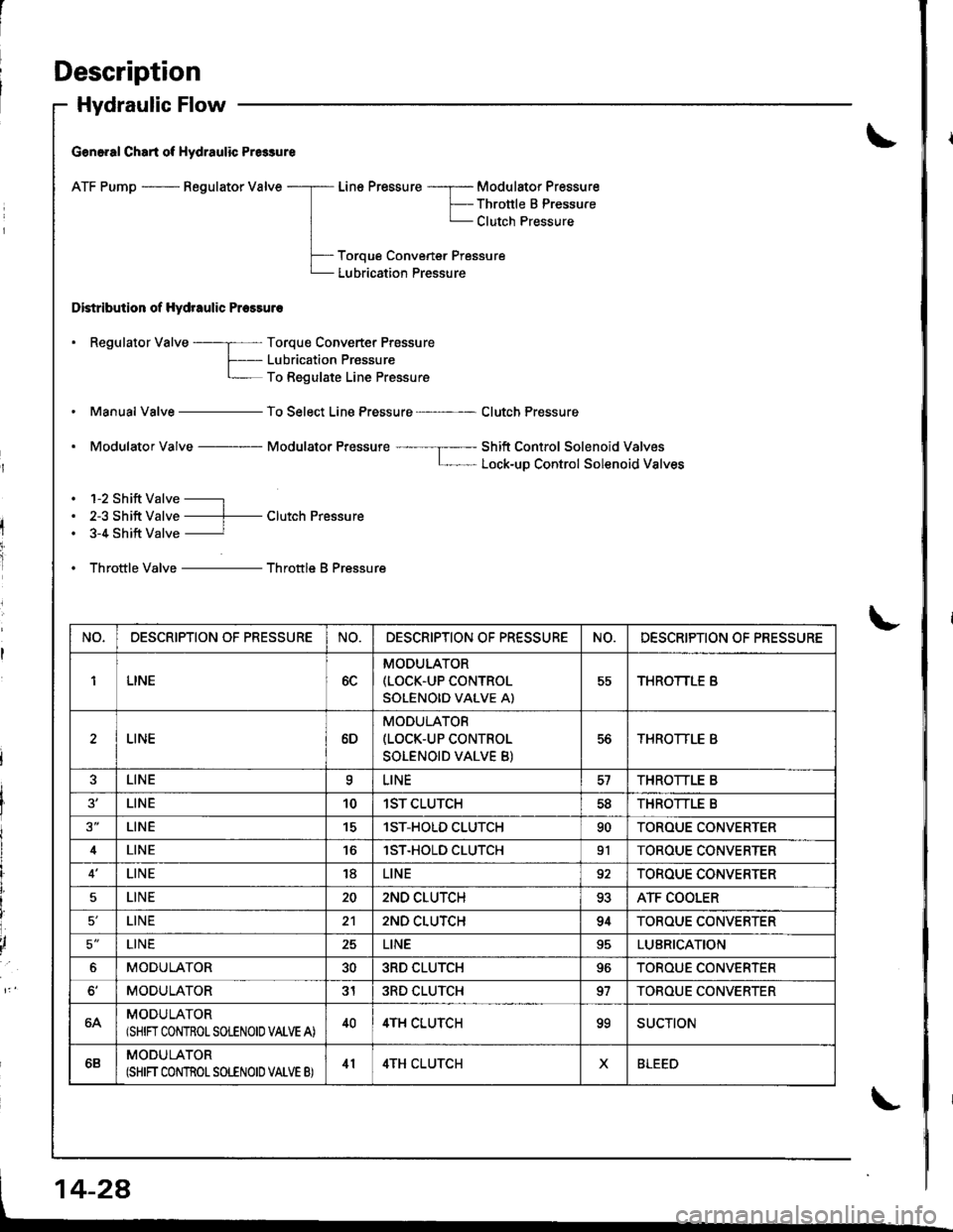
Hydraulic Flow
G€n6.al Chart of Hydraulic Pr6sure
ATF Pump - Regulator Valve
Distribution of Hydraulic Pressuro
Line Pressure -----r- Modulator Pressure
F-- Thronle B PressureL Clutch Pressure
Toroue Convener Pressure
Lubrication Pressure
. Regulator Valve ----; Torque Converter Prossure
f- Lubricaiion PrassureL To Regulate Line Pressure
Manual Valve - To Select Line Pressure - Clutch Pressure
. Modulator Valve Modulator Pressure ---- --I----- Shift Control Solenoid ValvosL- Lock-uD Control Solenoid Valves
. 1-2 Shift Valve -----l
. 2-3 Shift Valve ----f- Clutch Pressure. 3-4 Shift Valve ----------r
. Throttle Valve - Throttle B Pressure
NO,DESCRIPTION OF PRESSURENO.DESCRIPTION OF PR€SSURENO.DESCRIPTION OF PRESSURE
1LINE6C
MODULATOR(LOCK.UP CONTROL
SOLENOID VALVE A)
55THROTTLE B
LINE6D
MODULATOR(LOCK-UP CONTROL
SOLENOID VALVE B)
56THROTTLE B
LINEaLINETHROTTLE B
LINE101ST CLUTCH5dTHROTTLE B
LINE151ST-HOLD CLUTCH90TOROUE CONVERTER
4LINElST.HOLD CLUTCH91TOROUE CONVERTER
LINE18LINE92TOROUE CONVERTER
5LINE202ND CLUTCH93ATF COOLER
LINE212ND CLUTCH94TOROUE CONVERTER
5'LINE25LINELUBRICATION
6MODULATOR303RD CLUTCH96TOROUE CONVERTER
MODULATOR313RD CLUTCH97TOBOUE CONVERTER
64MODULATOR(SHIN CONTROLSOLENOIO VALVE A)404TH CLUTCHooSUCTION
6BMODULATOR(SHIFT CONTROT SOLENOID VATVE B)414TH CLUTCHXBLEED
Page 445 of 1680
I
I
I
Llfl Position
As the engine turns, the ATF pump also starts to operate. Automatic transmission fluid (ATF) is drawn from (99) and
discharged into (1). Then, ATF pressure is controlled by the regulator valve and becomes line pressure (1). The torque
converter inlet pressure {92} enters (94) ol torque converter through the orilice and discharges into {9O).
The torque converter check valve prevents the torque converter pressure from rising.
Under this condition, the hydraulic pressure is not applied to the clutches.
NOTE: When used, "l€ft" or "right" indicates direction on the hydraulic circuit.
(cont'dl
14-29