1998 ACURA INTEGRA valve
[x] Cancel search: valvePage 355 of 1680

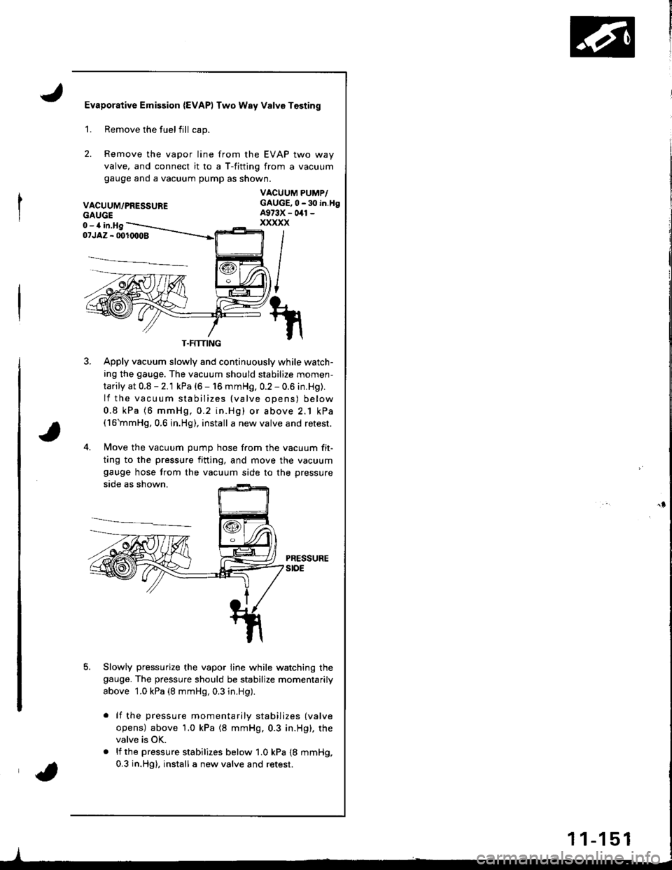
Evaporative Emission {EVAPI Two Way Valve Tosting
2.
Remove the fuelfill cap.
Remove the vapor line from the EVAP two way
valve, and connect it ro a T-fitting from a vacuum
gauge ano a vacuum pump as shown.
VACUUM/PRESSURE
1.
GAUGE0-a in,Hg
VACUUM PUMP/GAUGE,0 - 30 in.tlgA973X - 041 -
xxxxx
i/NI
t/
il\/
1il|
07JAZ - 001(X)08
3. Apply vacuum slowly and continuously while watch-
ing the gauge. The vacuum should stabilize momen-
tarily at 0.8 - 2.1 kPa (6 - 16 mmHg, 0.2 - 0.6 in.Hg).
lf the vacuum stabilizes {valve opens) below
0.8 kPa (6 mmHg,0.2 in.Hg) or above 2.1 kPa(16'mmHg,0.6 in.Hg), install a new valve and retest.
4. Move the vacuum oumo hose from the vacuum fit-
ting to the pressure fining, and move the vacuum
gauge hose from the vacuum side to the pressure
side as shown.
PRESSUREstoE
Slowly pressurize the vapor line while watching thegauge. The pressure should be stabilize momentarily
above 1.0 kPa (8 mmHg, 0.3 in.Hg).
lf the pressure momentarily stabilizes (valve
opens) above'1.0 kPa (8 mmHg.0.3 in.Hg), the
valve is OK.
lf the pressure stabilizes below 1.0 kPa {8 mmHg,
0.3 in.Hg), install a new valve and retest.
T.FMING
1 1-1 51
Page 417 of 1680

Automatic Transmission
Special Tools ................ '14-2
Descraption .................... 14-3
Clutches ............ ...... 14-6
Power Flow ..,........... 14-8
Electronic Control System ..................... 1 4-1 8
Hydraulic Control ...... 14-23
Hydraulic Flow .........- 14-28
Lock-up System ........ 14-38
Electrical System
Component Location -................................ 1 4-45
Circuit Diagram ............. 14-46
TCM Terminal Voltage/
Measuring Conditions ......,.................... 1 4-48
Troubleshooting Procedures .. . ... ........ ...... ... 14-50
Symptom-to-Component Chart
Electrical System ...... 14-54
Electrical Troubleshooting
Troubleshooting Flowcharts .......... ... ...,.. 14-56
Lock-up Control Solenoid Valve A/B Assembly
Test .................. ...... 14-A7
Replacement ............. 14-a7
Shilt Control Solenoid Valve A/B Assembly
Test .................. ...... '14-88
Replacement .,..,........ 14-88
lvlainshaf t/Countershaft Speed Sensors
Replacement ....-......,. 14-89
Transmission Control Module (TCM)
Replacement ............. 14-89
Hydraulic System
Symptom-to-Component Chart
Hydraulic System ...... 14-90
Road Test ,................... 14-94
Stall Speed
Test .................. ...... 14-97
Fluid Level
Checking/Changing .... 14-98
Pressure Testing ........... 14-99
Transmission
Transmission
Removal ............. ...... 14-10�4
lllustrated lndex
Transmission/Right Side Cover ............... 1 4-1 08
Transmission Housin9 ................,..,....... 1 4-1'1 O
Torque Converter Housing/ValveBody .................. .. 14-112
Right Side Cover
Removal ............. ...... 14-114
Transmission Housing
Removal ............. ...... 14-1 l6
Torque Converter Housing/Valve Body
Removal ............. ...... l4-1 18
Valve Caps
Description ...........-... 14-120
Valve Body
Repair ................ ...... 14-12'l
Valve
Assembly
ATF Pump
Inspeclton
Main Valve Body
Disassembly/lnspection/Reassembly
Regulator Valve Body
Disassembly/lnspection/Reassembly
Lock-up Valve Body
Disassembly/lnspection/Reassembly
Secondary Valve Body
Disassembly/lnspection/Reassembly
Servo Body
....... 14-124
....... 14-126
....... 14-127
....... 14 124
Disassembly/lnspection/Reassembly .......
1st-hold Accumulator/Right Side Cover
Disassembly/lnspection/Reassembly .......
Mainsha{t
14-130
14-132
Disassembly/lnspection/Reassembly ....... 14-133
Inspection ................. 14-134
Countershaft
Disassembly/lnspection/Reassembly,..,.., l4-136
Disassembly/Reassembly ..,...,..,.........,,.. 1 4-1 37
Inspection ......,...,..,... 14-138
One-way Clutch
Disassembly/lnspection/Reassembly ....,.. 14-141
Sub-shaft
Disassembly/lnspection/Reassembly ...,,..'14-142
Disassembly/Reassembly ....................... 1 4- l 43
Sub-shaft Bearings
Replacement ,..,,.,,..,.. 14-144
Clutch
lllustrated Index ................................... I 4-1 45
Disassembly ............. 14-144
Reassembly .............. 14-150
Torque Converter Housing Bearings
Mainshaft Bearing/Oil Seal
Replacement ......... 14-154
Countershaft Bearing Replacement ......... 1 4- 1 55
Transmission Housing Bearings
Mainshaft/Countershaft BearingReplacement ......,.. 14-'156
Sub-shaft Bearing Replacement .,............ 1 4-1 57
Reverse ldler Gear
Installation .........-..... 14-158
Parking Brake Stop
Inspection/Adjustment .......................... 1 4-1 58
Transmission
Reassembly .............. 14-160
Torque Converler/Drive Plate ..............,.,,.,, 1 4-1 67
Transmission
Installation ............... 14-168
Cooler Flushing ......... 14-172
ATF Cooler Hoses
Connection ,..,,,....,,.,, '14-'174
*shift cable
Removal/lnstallation . . .. .... ... .... ... .... .. . ... .. 14-'l75
Adjustment ,..,...,,,,.,, 14-'116*Shilt lever
Disassembly/Reassembly ....................... 1 4-'17 7'Shift Indicator Panel
Adjustment .............. 14-178
\l
)g
Page 419 of 1680

Description
\J
t{
{
14-3
The automatic transmission is a combination of a 3-element torque converter and triple-shalt electronically controlled
automatic transmission which provides 4 speeds forward and 1 speed reverse. The entire unit is positioned in line with
the engrne.
Torque Converter, Gears, and Clutches
The torque converter consists of a pump, turbine, and stator, assembled in sigle unit. The torque converter is connected to
the engine crankshaft so they turn torether as a unit as the engine turns. Around the outside of the torque convener is a
ring gear which meshes with the starter pinion when the engine is being started. The entire torque converter assembly
serves as a flywheel while transmitting power to the transmission mainshaft.
The transmission has three parallel shafts; the mainshaft. the countershaft, and the sub shaft. The mainshaft is in-line with
the engine crankshaft.
The mainshaft includes the 1st, and 2ndl4th clutches,and gear for 3rd, 2nd, 4th, reverse, and 1st. (3rd gear is integral with
the mainshaft, while reverse gear is integral with the 4th gear.)
The countershaft includes the 3rd clutch and gears for 3rd,2nd, 4th, reverse, 1st, and parking. Reverse and 4th gears can
be loched to the countershaft at its center,providing 4th gear or reverse, depending on which way the selector is moved.
The sub-shaft includes the 1st-hold clutch and gears fo 1st and 4th.
The gears on the mainshaft are in constant mesh with those on the countersahft and sub-shaft.When certain combinations
of gears in the transmission are engaged by clutches. power in transmitted from the mainshaft to the countershaft via the
sub-shaft to orovude oil, lo'1. E, E. and E.
Electronic Control
The electronic control svstem consists of the Transmission Control Module (TCM), sensors, and four solenoid valves.
Shilting and lock-up are electronically controlled for comfortable driving under all conditions.
The TCM is located below the dashboard, behind the lelt side kick panel on the driver's side.
Hydraulic Control
The valve bodies include the main valve body, the secondary valve body, the regulator valve body, the serbvo body, and
the lock-up valve body, through the respective separator plates, They are bolted to the torque converter housing,
The main valve body contains the manual valve, the 1-2 shift valve, the 2-3 shitt valve, the Clutch Pressure Control
lCPC) valve, the 4th exhaust valve, the reliel valve, and the ATF pump gears.
The secondary valve body contains the 4-3 kick-down valve, the 3-2 kick-down valve, the 2-3 orifice control valve, the
3-4 shift valve, the orilice control valve, the modulator valve, and the servo control valve.
The regulator valve body contains the pressure regulator valve, the lock-up control valve, the torque converter check
valve, and the cooler check valve.
The servo body contains the servo valve, which is integrated with shift fork shaft, the throttle valve B, and the accumula-
tors.
The lock-up valve body contains the lock-up shift valve and the lock-up timing B valve, and is bolted to the regulator valve
ooqy.
Fluid from the regulator passes through the manual valve to the various control valves.
Shift Control Mechanism
Input to the TCM from various sensors located throughout the car determines which shift control solenoid valve should
be activated. Activating a shitt control solenoid valve changes modulator pressure, causing a shift valve to move. This
pressurizes a line to one ol the clutches, engaging that clutch and its corresponding gear.
Lock-uD Mechanism
In @ position, in 2nd, 3rd and 4th, and @ position in 3rd, pressurized fluid can be drained lrom the back oI the tor-
que converter through a fluid passage, causing the lock-up piston to be held against the torque converter cover. As this
takes place, the mainshaft rotates at the same speed as the engine crankshaft. Together with hydraulic control, the TCM
optimizes the timing of the lock-up mechanism.
The lock-up valves controlthe range of lock-up according to lock-up control solenoid valves A and B, and throttle valve B.
When lock-up control solenoid valves A and B activate, modulator pressure changes. Lock-up control solenoid valves
A and B are mounted on the torque converter housing, and are controlled by the TCM.
(cont'd)
Page 421 of 1680

I
,
TOROUEASSEMBLY
VEHICLE SPEED SENSOR IVSS}
VALVEBODIES
1ST HOLD CLUTCH
3RD CLUTCH
COUNTERSHAFTSPEED SENSOR
MAINSHAFTSPEED SENSOR
1ST CLUTCH
I
I
COUNTERSHAFT
14-5
Page 425 of 1680
![ACURA INTEGRA 1998 Service Repair Manual l
t
LNI Position
Hydraulic pressure is not applied to the clutches. Power is not transmitted to the countershaft.
[] Position
Hydrsulic pressure is not applied 10 the clutches. Power is not transmitt ACURA INTEGRA 1998 Service Repair Manual l
t
LNI Position
Hydraulic pressure is not applied to the clutches. Power is not transmitted to the countershaft.
[] Position
Hydrsulic pressure is not applied 10 the clutches. Power is not transmitt](/manual-img/32/56983/w960_56983-424.png)
l'
t
LNI Position
Hydraulic pressure is not applied to the clutches. Power is not transmitted to the countershaft.
[] Position
Hydrsulic pressure is not applied 10 the clutches. Power is not transmitted to the countershaft.
The countershaft is locked by the parking brake pawl interlocking the parking gear.
TOROUE CONVERTEB
PARKING GEAR
REVERSE SELECTOR
REVERSE GEAR
REVERSE SEI.ECTORHUB
SERVO VALVE/SHIFT FORK SHAFT
{cont'd)
14-9
Page 433 of 1680

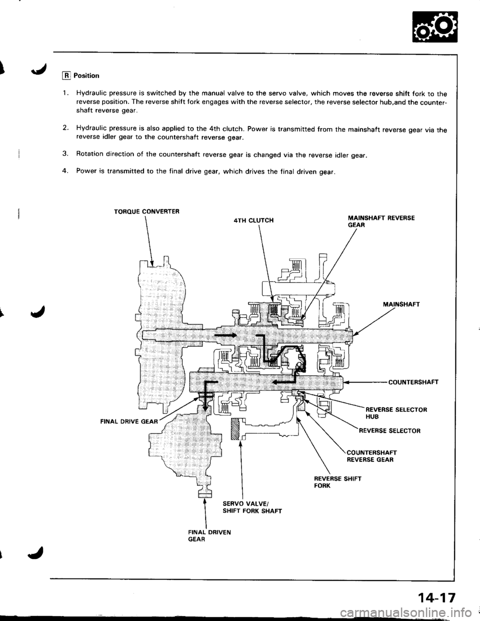
ILB.l Position
'1. Hydraulic pressure is switched by the manual valve to the servo valve, which moves the reverse shitt fork to thereverse position. The reverse shitt fork engages with the reverse selector, the reverse selector hub,and the counter-shaft reverse gear.
2. Hydraulic pressure is also applied to the 4th clutch. Power is transmitted from the mainshaft reverse gear vta rnereverse idler gear to the countershalt reverse gear.
3. Rotation direction of the countershaft reverse gear is changed via the reverse idler gear.
4. Power is transmitted to the final drive gear, which drives the linal driven gear.
TOROUE CONVERTER
4TH CLUTCH
MAINSHAFT
COUNTERSHAFT
REVERSE SELECTORHUBFINAL ORIVE GEAR
REVENSE SELECTOR
COUNTERSHAFTREVERSE GEAR
Page 434 of 1680

Description
Electronic Control SYstem
14-18
{The electronic control system consists of the Transmission control Module {TcM), sensors, and four solenoid valves'
shifting and lock-up are electronically controlled tor comfortable driving under all conditions
The TCM is located below the dashboard, behind the left side kick panel on the driver's side.
Shilt Control
Lock-up ControlSolenoid Valve A
Lock up Control
Lock-up ControlSolenoid Valve I
I
Page 435 of 1680

Lock-uD Control
From sensor input signals, the TCM determines whether to turn the lock-up ON or OFF and activates lock-up control
solenoid valve A and/or B accordingiy. The combination oI driving signals to lock up control solenoid valves A and B
is shown in the table below.
ShiIt Contlol
The TCM instantaneously determines which gear should be selected by various signals sent from sensors, and actuates
the shift control solenoid valves A and B control shifting. Also, a Grade Logic Control System has been adopted to control
shifting in @ position while the vehicle is ascending or descending a slope, or reducing speed.
w"'u"
Lock-up condition
-\B
Lock'up OFFOFFOFF
Lock-up, slightONOFF
Lock-up, halfONON
Lock up, fullONON
LOCK-Upduring decelerationONDuty operationOFF-ON
Shift control solenoid valve
t"dil"" d;------\
B
tc!t' tcll
{1st)OFFON
(2nd )ONON
(3rd)ONOFF
{4th)OFFOFF
e {2nd)ONON
tr (1st)ONOFF
tr (Reverse)ONOFF
I'
(cont'd)
14-19