Page 875 of 1680

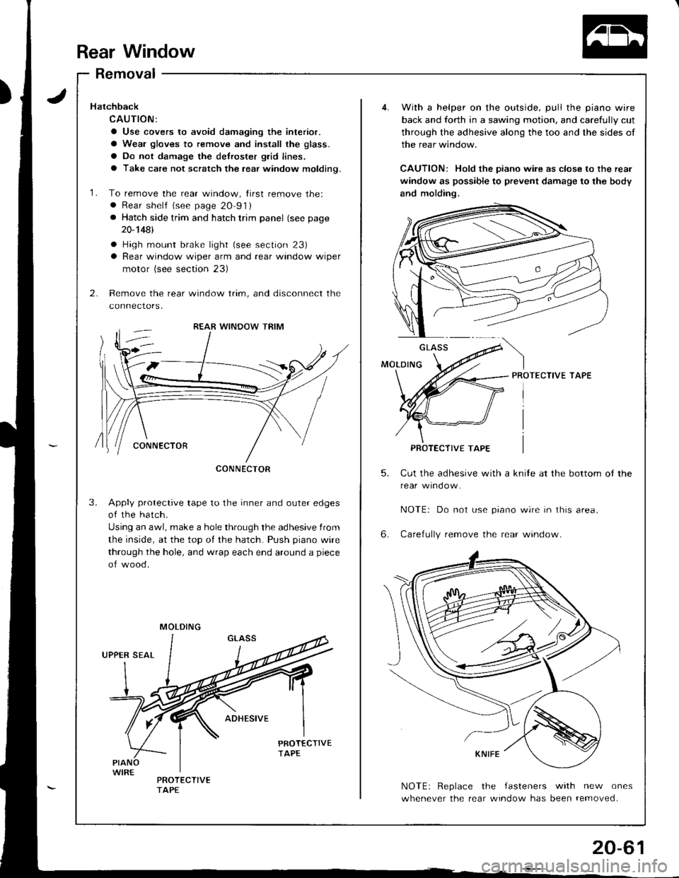
Rear Window
Removal
5.
6.
With a helper on the outside, pull the piano wire
back and forth in a sawing motion, and carefully cut
through the adhesive along the too and the sides of
the rear window.
CAUTION: Hold the piano wile as close to the rear
window as possible to prevent damage to the body
and molding.
PROTECTIVE TAPE
Cut the adhesive with a knile at the bottom ot the
NOTE| Do not use prano wrre In lhrs area.
Carefully remove the rear window.
NOTEr Replace the fasteners with new ones
whenever the rear window has been removed.
GLASS
PROTECTIVE TAPE
Hatchback
CAUTION:
a Use covers to avoid damaging the interior.
a Wear gloves to remove and install the glass.
a Do not damage the defroster glid lines.
a Take care not scratch the rear window moldino.
1. To remove the rear window, tirst remove the:. Rear shelf (see page 20 91). Hatch side trim and hatch trim panel (see page
20-14A1
a High mount brake light (see section 23)a Rear window wiper arm and rear window wiper
motor (see section 23)
2. Remove the rear window trim, and disconnect the
connectors,
Apply protective tape to the inner and outer edges
of the hatch.
Using an awl, make a hole through the adhesive from
the inside, at the top of the hatch. Push piano wire
through the hole, and wrap each end around a piece
of wood.
3.
CONNECTOR
MOLDING
Page 892 of 1680

Moonroof
Troubleshooting
SymptomP.obable Cause
Clogged drain tube.
Gap between glass weatherstrip and roof panel
De{ectrve or improperly Installed glass weatherstrip
Gap between drain seal and rool panel.
Excessive clearance between glass weatherstrip and roof panel-
Loose motor.
Worn gear or bearing.
Cable assemblv deformed.
1
2
3
4
1
2
3
1.
Water leaks
Wind noise
Motor noise
Glass does not move, but motor
turns
Clutch out ol adiustment.
Foreign matter stuck between guide rail and slider'
lnner cable loose.
Cable assembly not attached properly
,l
2
3
4
Glass does not move and motor
does not turn (glass can be moved
with moonroof wrench)
1. Blown fuse.
2. Faulty switch.
3. Battery run down.
4. Delective motor.
5. Faulty relay.
Glass Height Adiustment
The roof panel should be even with the glass weather-
srrip, to within 1.8 t O.5 mm {O.07 t 0.02 in} all the
way around. lf not, slide the sunshade back, and:
1. Tilt-up the glass.
2. Loosen the bolts and adjust the glass.
3. Repeat on opposite side if necessary.
1.8 i 0.5 mm 10.07 i 0.02 inl
V : Boll locations, 6
]-
ROOF PANELGLASS BRACKET
Side-to-side iit of glass weatherstrip can be adJust-
ed by loosening the frame mounting bolts and mov-
ing the frame right or left and {orward or backward
by hand (see page 2O-8Oi.
GLASS BRACKETGLASS WEATHERSTRIP
{
$
I
!
20-78
Page 899 of 1680

)
Troubleshooting
Glass Height Adjustment
The rooJ panel should be even with the glass weather
strip, to within 1.8 t 0.5 mm (O.O7 tO.O2 in) allthe way
around. It not, slide the sunshade back, and:
1. Tilt-up the glass.
2. Loosen the bolts and adjust the glass.
3. Repeat on opposite side if necessary.
1.810.5 mm {0.07 } 0.02 inl
Gr_ASS
4-(.'
ROOF PANELGLASS BRACKET
GLASS WEATHERSTRIP
4. Side-to-side fit oI glass weatherstrip can be adjust-
ed by loosening the frame mounting bolts and mov
ing the frame right or left and forward or backward
by hand (see page 20-87).
GLASS BRACKET
SymptomProbable Cause
Water leaks1. Clogged drain tube.
2. Gap between glass weatherstrip and roof panel.
3. Detective or improperly installed glass weatherstrip.
4. Gap between drain seal and roof panel.
Wind noise1. Excessive clearance between qlass weatherstriD and roof oanel.
Motor noiseI
2
3
Loose motor.
Worn gear or bearing.
Cable assembly deformed.
Glass does not move, but motor
turnS
1
2
3
Clutch out of adjustment.
Foreign matter stuck between guide rail and slider.
lnner cable loose.
Cable assembly not attached properly.
Glass does not move and motor
does not turn (glass can be moved
with moonroof wrench)
I
2
3
Blown fuse.
Faulty switch.
Battery run down.
Defective motor.
Faulty relay.5
{
s
I
20-85
Page 903 of 1680
1O. Separate the glass bracket,
and slider.
INNER CABLE
litt€r, slide stopper link
GLASSBRACKET
11.
SLIDER
NOTE: To install, apply multipurpose greaseto the lifter and slide stopper link.
Slide the anchor rod forward, then remove it from
the guide rail.
STOPPER
To install, insert the anchorrod by turnjng the stopper 9Oo.
ANCHOR ROD
14.
20-89
'12.Slide the guide rail backward, then remove the guide
rail from the inner cable.
NOTE: To install, apply caulking to the guide rail
mounting surtace on the frame.
Apply caolking beforeinstalling the guide rail.
'13. Remove the screws, then remove the cable assem
bly trom the f rame.
NOTE: Take care not to bend the cable tubes.
NOTE: To install, fill the groove Ineach grommet with sealant.
Installation is the reverse of the removal procedure.
NOTE:
a Damaged parts should be replaced.
a Apply grease to the sliding portion.
FRAME
Page 909 of 1680
Rear pillar trim panel/Rsar shelf trim panel/Real shelt
removal:
1. Remove both seat-back side bolsters {see page 20-
113).
2. Remove the upper portion of the rear door sill mold-
ing, then pull the rear door trim away on each side.
> : Clip locations, 2
REAR PILLAR TRIM PANEL
SII-I MOLDING
3. Remove both rear pillar trim panels.
> | Clip locations, 12
NOTE: When installing, make surethe rear window defogger wireharness is routed properly.
1
I
,
4. Remove the rear shell trim panel.
V: Clip locations, 2
5. Slip the rear seat belt through the slit in the rear shelf.
REAR SHELF
Remove the seat lock cover (see page 20 113) and
high mount brake light (see section 23).
20-95
Page 931 of 1680

zril
HSeat Belts
I
I
Front Seat Belt Replacement
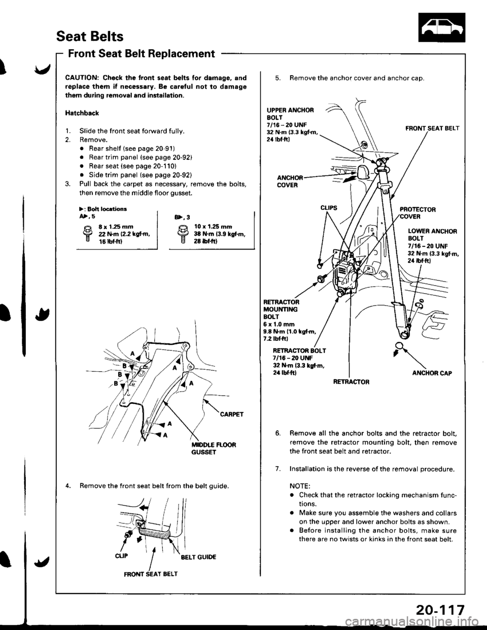
CAUTION: Ch€ck the tront seat belts for dsmage, and
replace them if necessary. Be car€ful not to damage
them during removal and installation.
Hatchback
1. Slide the front seat forward fully.
2. Remove.
. Rear shelf (see page 20-91)
. Rear trim panel (see page 20-92)
. Rear seat {see page 20-110}
. Side trim panel {see page 20-92)
3. Pull back the carpet as necessary, remove the bolts,
then remove the middle floor gusset.
>:8oh locldonsA>, 5
€t 8r1.25mmp zz trt'm tz.z rgf.m,e 16 bf.ftl
10 x t.25 mm:ta N.m 13.9 kgf.m,26 tbrftl
8>, 3
4. Remove the front seat belt from the belt quide.
BELT GUIDE
5. Remove the anchor cover and anchor cap.
UPPER ANCHOREOLT7/16 - 20 UNF32 N.m (3.3 kgt m,24 rbf.ftl
RETRACTORMOUNTI]IIGBOLT6r1.0mm9.8 N.m 11.0 tgf.m,1.2 tblJftl
PROTECTOR
LOWER ANCHORBOLT7/16-20 UNF32 N.m {3.3 kg{.m,24 tbf.ftl
ANCHOR CAP
AL-
RETMCTOR BOLT7/16 - 20 UtrtF32 N.m 13.3 lgi.m,2'a tbt ftl
7.
Remove all the anchor bolts and the retractor bolt.
remove the retractor mounting bolt, then remove
the front seat belt and retractor.
Installation is the reverse of the removal procedure.
NOTE:
o Check that the retractor locking mechanism func-
I|ons.
. Make sure you assemble the washers and collars
on the upDer and lower anchor bolts as shown.. Before installing the anchor bolts, make sure
there are no twists or kinks in the front seat belt.
RETRACTOR
Page 932 of 1680

Seat Belts
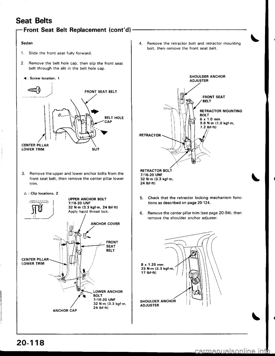
Front Seat Belt Replacement {cont'd}
Sedan
1. Slide the lront seat fully lorward.
2. Remove the belt hole cap, then slip the front seat
belt through the slit in the belr hole cap.
<: Screw location, 1
FRONT SEAT BELT
CENTERLOWER
3. Remove the uoDer and lower anchor bolts from the
front seat belt, then remove the center pillar lower
trim.
UPPER ANCHOR BOLT7/16-20 UNF32 N.m {3.3 kgl n, 24 lbt.tt)Apply liquid thread lock.
ANCHOR
$..
COVER
FRONTSEATBELT
LOWER ANCHORBOLT7/16-20 UNF32 N.m 13.3 ksf m,24 tbl.trl
I
I
I
/PILLARTRIM
A : Clip locations, 2
.144l I
Il ru, I
_:,t __,)
SLIT
20-118
ANCHOR CAP
4. Remove the retractor
bolt, then remove the
bolt and retractor mounting
Iront seat belt.
FRONT SEATBELT
RETRACTOR MOUNTINGEOLT6 x 1.0 mm9.8 N.m (1.O kgl m,7 .2 tbl.ltl
RETRACTOR
RETRACTOR BOLT7/16-20 UNF32 N.m (3.3 kgf.m,24 tbt.ft)
6.
Check that the retractor locking mechanism func-
tions as described on page 20-124.
Remove the center pillar trim (see page 20-94), then
remove the shoulder anchor adiuster.
8 x 1.25 mm23 N.m (2.3 kgt.m,17 lbr.frl
Page 935 of 1680
J
v
CAUTION: Check the.oar s€at belts tor damago, and l€placo th€m il necossary. Be carelul not to damage them during
r€moval and installation,
Hatchback
1. Remove:
. Rear shelf (see page 2O-91)a Rear trim panel (see page 20-92)
a Rear seat (see page 20-110)
a Side trim panel (see page 20 92)
2.Remove all the anchor bolts, the retractor bolt and the retractor mounting bolt, then remove the rea. seat belt and
center belt.
Check that the retractor locking mechanism functions as described on page 20-124,
RETRACTOR MOUNTINGBOLT6 x 1.0 mm9.8 N.m 11.0 kgf.m,7.2 tbt.ltlUPPER ANCHOR BOLT7/16-20 UNF32 N.m {3.3 kgl.m,24 tbl.lrl
COVER
RETRACTOR
REAR SEATBELT
RETRACTOR BOLT7/16-20 UNF32 N.m (3.3 kgf.m,24 tbt.ft)PROTECTORCOVER
CENTER BELT
LOWER ANCHOR BOLT7/16,20 UNF32 N.m {3.3 kgI.m,24 lbr.frl
T SELTBUCKLE
CENTER ANCHOR BOLT7/'16-20 UNF32 N.m (3.3 kgt.m,24 lbf.Ir)(cont'd )a