Page 25 of 3342
![SUBARU LEGACY 1997 Service Repair Manual 4-4
[wzsc2]
SERVICE
PROCEDURE
25
.
ABS
Control
Module
and
Hydraulic
Control
Unit
(ABSCM&H/U)
(ABS
5
.3i
Type]
{~~Y+)~
_~00
G4M0464
2
.
CHECKINGTHE
HYDRAULIC
UNIT
ABS
OPERATION
WITH
BRAKE
TESTER](/manual-img/17/57434/w960_57434-24.png "SUBARU LEGACY 1997 Service Repair Manual 4-4
[wzsc2]
SERVICE
PROCEDURE
25
.
ABS
Control
Module
and
Hydraulic
Control
Unit
(ABSCM&H/U)
(ABS
5
.3i
Type]
{~~Y+)~
_~00
G4M0464
2
.
CHECKINGTHE
HYDRAULIC
UNIT
ABS
OPERATION
WITH
BRAKE
TESTER")
4-4
[wzsc2]
SERVICE
PROCEDURE
25
.
ABS
Control
Module
and
Hydraulic
Control
Unit
(ABSCM&H/U)
(ABS
5
.3i
Type]
{~~Y+)~
_~00
G4M0464
2
.
CHECKINGTHE
HYDRAULIC
UNIT
ABS
OPERATION
WITH
BRAKE
TESTER
1)
In
the
case
of
AWD
AT
vehicles,
install
aspare
fuse
with
the
FWD
connector
in
the
engine
compartment
to
simu-
late
FWD
vehicles
.
2)
Prepare
for
operating
ABS
sequence
control
.
<
Ref,to
[W25D1
]*10
or
[W25D2]
.*10
>
3)
Setthe
front
wheels
orrear
wheels
on
the
brake
tester
and
set
the
select
lever's
position
at
"neutral"
.
4)
Operate
the
brake
tester
.
5)
Perform
ABS
sequence
control
.
<
Ref
.
to
[W25D1]*10
step
1
or
[W25D2]*10
step
1
.
>
6)
Hydraulic
unit
begins
to
work
;
and
check
the
following
working
sequence
.
(1)
The
FL
wheel
performs
decompression,
holding,
and
compression
in
sequence,
and
subsequently
the
FR
wheel
repeats
the
cycle
.
(2)
The
RR
wheel
performs
decompression,
holding,
and
compression
in
sequence,
and
subsequently
the
RL
wheel
repeats
the
cycle
.
7)
Read
values
indicated
on
the
brake
tester
and
check
if
the
fluctuationof
values,
when
decompressed
and
compressed,
meet
the
standard
values
.
Unit
:
N
(kg,
Ib)
Initial
value
When
decompressed
When
compressed
Front
wheel
981
(100,
221)
490
(50,
110)or
less
981
(100,
221)
or
more
Rear
wheel
981
(100,
221)
490
(50,
110)
or
less
981
(100,
221)or
more
8)
After
checking,
also
check
if
any
irregular
brake
pedal
tightness
is
felt
.
10
Page 103 of 3342
![SUBARU LEGACY 1997 Service Repair Manual
BRAKES
[ABS
5
.3i
TYPE]
IT8Y3J4-4d
8
.
Diagnostics
Chart
with
Trouble
Code
by
ABS
Warning
Light
`G/
Tn]
1
Mark
~-ABSCM&HlU
g4M1248A
P11
2
1
D
+V-
B4M0911
B
8YI
CHECK
TURNING
LL
FOUR
WHEEL](/manual-img/17/57434/w960_57434-102.png "SUBARU LEGACY 1997 Service Repair Manual
BRAKES
[ABS
5
.3i
TYPE]
IT8Y3J4-4d
8
.
Diagnostics
Chart
with
Trouble
Code
by
ABS
Warning
Light
`G/
Tn]
1
Mark
~-ABSCM&HlU
g4M1248A
P11
2
1
D
+V-
B4M0911
B
8YI
CHECK
TURNING
LL
FOUR
WHEEL")
BRAKES
[ABS
5
.3i
TYPE]
IT8Y3J4-4d
8
.
Diagnostics
Chart
with
Trouble
Code
by
ABS
Warning
Light
`G/
Tn]
1
Mark
~-ABSCM&HlU
g4M1248A
P11
2
1
D
+V-
B4M0911
B
8YI
CHECK
TURNING
LL
FOUR
WHEELS
FOR
FREE
CHECK
:
Have
the
wheels
been
turned
freely
suchas
when
the
vehicle
is
lifted
up,
or
operatedon
a
rolling
road?
The
ABS
is
normal
.
Erase
the
trouble
code
.
Go
to
step
8Y2
.
CHECK
SPECIFICATIONS
OF
ABSCM&HIU
.
Check
specifications
of
the
mark
to
the
ABSCM&H/U
.
Mark
Model
C3
AWD
AT
C4
AWD
MT
1
'
he
an
dRSCM
fnr
dWn
MAIIPI
inciallprl
nna
FWD
model?
CAUTION
:
Be
sure
to
turn
ignition
switch
to
OFF
when
removing
ABSCM&H/U
.
,rES
:
Replace
ABSCM&H/U
.
No
:
Go
to
step
8Y3
.
18Y3
I
CHECK
INPUT
VOLTAGEOF
G
SENSOR
.
1)
Turn
ignition
switch
to
OFF
.
2)
Remove
console
box
.
3)
Disconnect
G
sensor
from
body
.
(Do
not
disconnect
connector
.)
4)
Turn
ignition
switch
to
ON
.
5)
Measure
voltage
between
G
sensor
connector
termi-
nals
.
Connector
&
terminal
(P11)
No
.
1
(+)
-
No
.
3
(
)
:
CHECK
:
Is
thevoltage
between
4
.75
and
5
.25
V?
Go
to
step
8Y4
.
No
:
Repair
harness/connector
between
G
sensor
and
ABSCM&H/U
.
85
Page 195 of 3342
![SUBARU LEGACY 1997 Service Repair Manual
BRAKES
[ABS
5
.31
TYPE]
[T10AG5]
4-4d
10
.
DiagnosticsChart
with
Select
Monitor
1997
(F00)
ABS
4WD
"
AT
H4M
11171
G-SENS
(F
10)
2
.30
V
sannos271
10AG1
HECK
I
US
G
SE
ECT,MONT
OR
OF
ABSC](/manual-img/17/57434/w960_57434-194.png "SUBARU LEGACY 1997 Service Repair Manual
BRAKES
[ABS
5
.31
TYPE]
[T10AG5]
4-4d
10
.
DiagnosticsChart
with
Select
Monitor
1997
(F00)
ABS
4WD
\"
AT
H4M
11171
G-SENS
(F
10)
2
.30
V
sannos271
10AG1
HECK
I
US
G
SE
ECT,MONT
OR
OF
ABSC")
BRAKES
[ABS
5
.31
TYPE]
[T10AG5]
4-4d
10
.
DiagnosticsChart
with
Select
Monitor
1997
(F00)
ABS
4WD
"
AT
H4M
11171
G-SENS
(F
10)
2
.30
V
sannos271
10AG1
HECK
I
US
G
SE
ECT,MONT
OR
OF
ABSCM&H/U
1)
Press
[F],
[0]
and
[0]
on
the
select
monitor
.
2)
Read
the
select
monitor
display
.
CH~K
:
Is
an
ABSCM&HlU
for
4WD
model
installed
on
a
FWD
model?
Replace
ABSCM&H/U
.
No
:
Go
to
step
10AG2
.
I10AG2
CHECK
OUTPUT
I
SELECT
MONITOR
F
G
SENSOR
USING
1)
Press
[F],
[1]
and
[0]
on
the
select
monitor
.
2)
Read
the
select
monitor
display
.
K
:
Is
theindicated
reading
between
2
.1
and
2
.5
V
when
the
G
sensor
is
in
horizontal
posi-
tion?
,rE$
:
Go
to
step
10AG3
.
Go
to
step
10AG6
.
I
10AG3
I
CHECK
POOR
CONTACT
IN
CONNECTORS
.
CHECK
:
Is
there
poor
contact
in
connector
between
ABSCM&HIU
and
G
sensor?
<
Ref
.
to
FORE-
WORD
[T3C1]
.*10
>
Repair
connector
.
No
:
Go
tostep
10AG4
.
10AG4
CHECK
ABSCM&HlU
.
1)
Connect
all
connectors
.
2)
Erase
the
memory
.
3)
Perform
inspection
mode
.
4)
Read
out
the
trouble
code
.
c
:
Is
the
same
trouble
code
as
in
thecurrent
diagnosis
still
being
output?
Replace
ABSCM&H1U
.
No
:
Go
to
step
i0AG5
.
10AG5
CHECK
ANY
I
APPEARANCE
.THER
TROUBLE
CODES
CHECK
:
Are
other
trouble
codes
being
output?
Proceed
withthe
diagnosis
corresponding
to
the
trouble
code
.
A
temporary
poor
contact
.
187
Page 229 of 3342
G2M0375
3. Canister
A: REMOVAL AND INSTALLATION
1. 2200 cc FWD AND 2500 cc MODEL
1) Disconnect canister hoses from evaporation pipes.
2) Remove canister with bracket.
3) Installation is in the reverse order of removal.
CAUTION:
Insert air vent hose of canister into the hole on body.
B2M0952
2. 2200 cc AWD MODEL
1) Lift-up the vehicle.
2) Disconnect evaporation hoses from canister.
B2M0953
3) Remove canister from body.
4) Installation is in the reverse order of removal.
Tightening torque:
25±7 N⋅m (2.5±0.7 kg-m, 18.1±5.1 ft-lb)
B2M1201A
4. Purge Control Solenoid Valve
A: REMOVAL AND INSTALLATION
1) Disconnect connector from purge control solenoid
valve.
2) Disconnect vacuum hoses from purge control solenoid
valve.
3) Remove bolt which installs purge control solenoid valve
to intake manifold.
4) Take out purge control solenoid valve.
7
2-1SERVICE PROCEDURE
3. Canister - 4. Purge Control Solenoid Valve
Page 230 of 3342
G2M0375
3. Canister
A: REMOVAL AND INSTALLATION
1. 2200 cc FWD AND 2500 cc MODEL
1) Disconnect canister hoses from evaporation pipes.
2) Remove canister with bracket.
3) Installation is in the reverse order of removal.
CAUTION:
Insert air vent hose of canister into the hole on body.
B2M0952
2. 2200 cc AWD MODEL
1) Lift-up the vehicle.
2) Disconnect evaporation hoses from canister.
B2M0953
3) Remove canister from body.
4) Installation is in the reverse order of removal.
Tightening torque:
25±7 N⋅m (2.5±0.7 kg-m, 18.1±5.1 ft-lb)
B2M1201A
4. Purge Control Solenoid Valve
A: REMOVAL AND INSTALLATION
1) Disconnect connector from purge control solenoid
valve.
2) Disconnect vacuum hoses from purge control solenoid
valve.
3) Remove bolt which installs purge control solenoid valve
to intake manifold.
4) Take out purge control solenoid valve.
7
2-1SERVICE PROCEDURE
3. Canister - 4. Purge Control Solenoid Valve
Page 482 of 3342
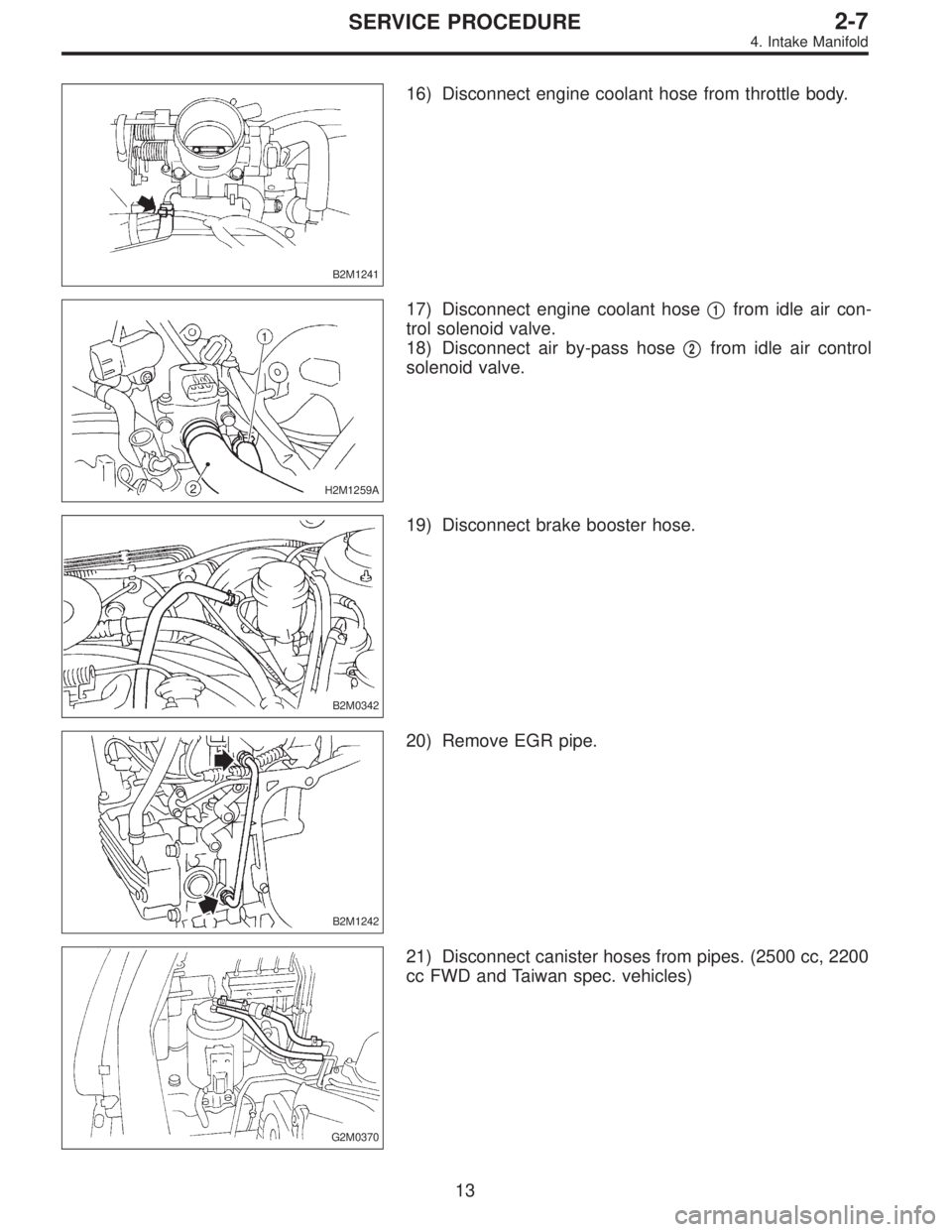
B2M1241
16) Disconnect engine coolant hose from throttle body.
H2M1259A
17) Disconnect engine coolant hose�1from idle air con-
trol solenoid valve.
18) Disconnect air by-pass hose�
2from idle air control
solenoid valve.
B2M0342
19) Disconnect brake booster hose.
B2M1242
20) Remove EGR pipe.
G2M0370
21) Disconnect canister hoses from pipes. (2500 cc, 2200
cc FWD and Taiwan spec. vehicles)
13
2-7SERVICE PROCEDURE
4. Intake Manifold
Page 488 of 3342
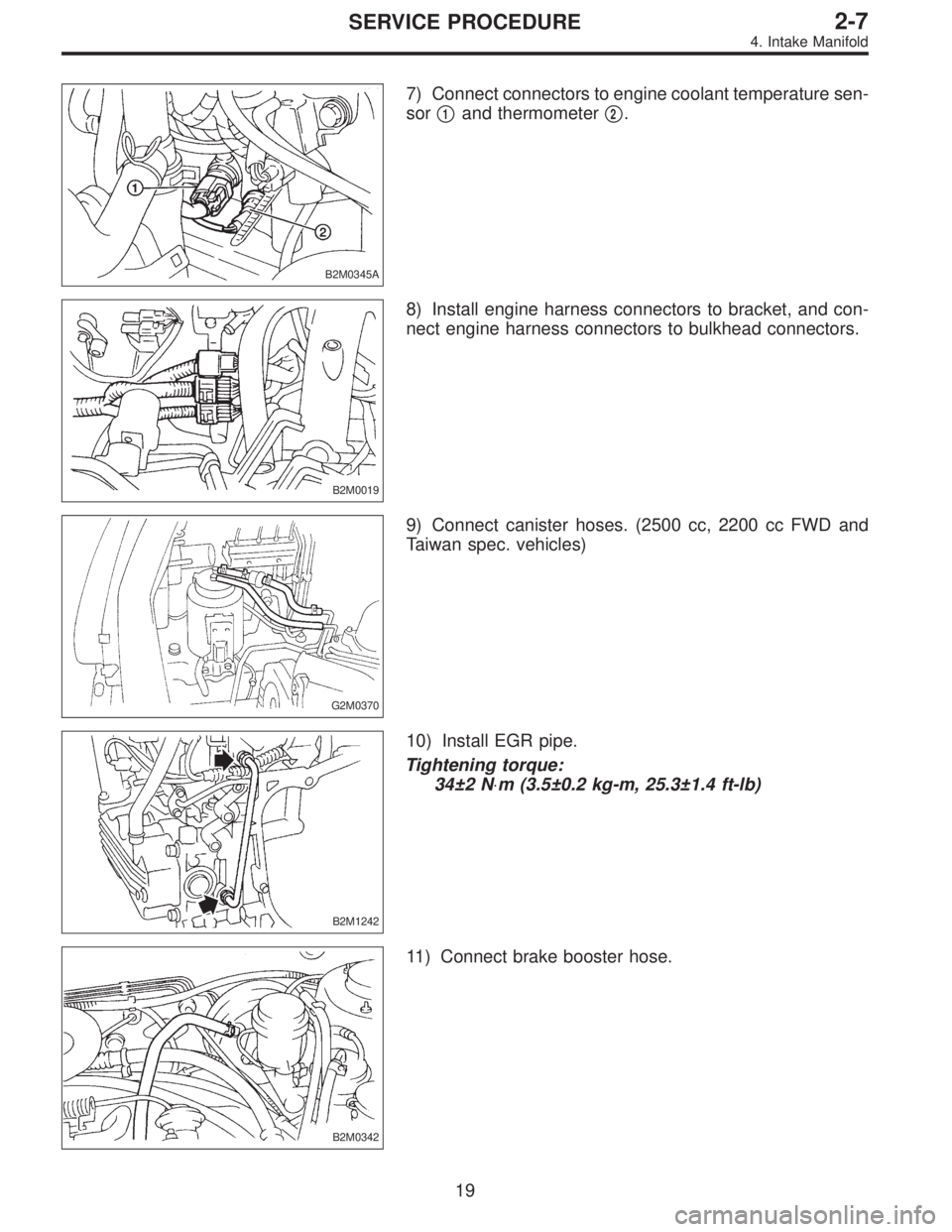
B2M0345A
7) Connect connectors to engine coolant temperature sen-
sor�
1and thermometer�2.
B2M0019
8) Install engine harness connectors to bracket, and con-
nect engine harness connectors to bulkhead connectors.
G2M0370
9) Connect canister hoses. (2500 cc, 2200 cc FWD and
Taiwan spec. vehicles)
B2M1242
10) Install EGR pipe.
Tightening torque:
34±2 N⋅m (3.5±0.2 kg-m, 25.3±1.4 ft-lb)
B2M0342
11) Connect brake booster hose.
19
2-7SERVICE PROCEDURE
4. Intake Manifold
Page 522 of 3342
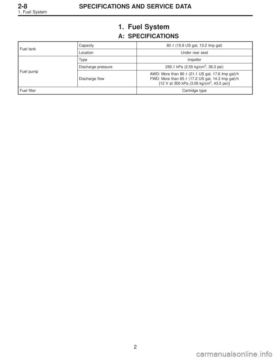
1. Fuel System
A: SPECIFICATIONS
Fuel tankCapacity 60�(15.9 US gal, 13.2 Imp gal)
Location Under rear seat
Fuel pumpType Impeller
Discharge pressure 250.1 kPa (2.55 kg/cm
2, 36.3 psi)
Discharge flowAWD: More than 80�(21.1 US gal, 17.6 Imp gal)/h
FWD: More than 65�(17.2 US gal, 14.3 Imp gal)/h
[12 V at 300 kPa (3.06 kg/cm
2, 43.5 psi)]
Fuel filterCartridge type
2
2-8SPECIFICATIONS AND SERVICE DATA
1. Fuel System
 Disconnect canister hoses from evaporation pipes.
2) Remove canister with bracket.
3) Installation is in the reverse")
 Disconnect canister hoses from evaporation pipes.
2) Remove canister with bracket.
3) Installation is in the reverse")