Page 1021 of 3342
G3M0505
7) Coat the seal ring with vaseline, and install it in the seal
ring groove of the shaft.
CAUTION:
Do not expand the seal ring excessively when install-
ing.
ST 899580100 INSTALLER
G3M0913
16. Transfer Valve Body
A: DISASSEMBLY
1) Remove the plate. Then remove the spring and pilot
valve together.
2) Remove the straight pin and pry out the plug with a
screwdriver. Then extract the spring and transfer clutch
valve together.
CAUTION:
Be careful not to damage the valve and valve body.
B: INSPECTION
Check each component for harmful cuts, damage, or other
faults.
C: ASSEMBLY
To assemble, reverse the removal sequence.
NOTE:
Make sure the valve slides smoothly after assembling.
11 2
3-2SERVICE PROCEDURE
15. Transfer Clutch - 16. Transfer Valve Body
Page 1022 of 3342
G3M0505
7) Coat the seal ring with vaseline, and install it in the seal
ring groove of the shaft.
CAUTION:
Do not expand the seal ring excessively when install-
ing.
ST 899580100 INSTALLER
G3M0913
16. Transfer Valve Body
A: DISASSEMBLY
1) Remove the plate. Then remove the spring and pilot
valve together.
2) Remove the straight pin and pry out the plug with a
screwdriver. Then extract the spring and transfer clutch
valve together.
CAUTION:
Be careful not to damage the valve and valve body.
B: INSPECTION
Check each component for harmful cuts, damage, or other
faults.
C: ASSEMBLY
To assemble, reverse the removal sequence.
NOTE:
Make sure the valve slides smoothly after assembling.
11 2
3-2SERVICE PROCEDURE
15. Transfer Clutch - 16. Transfer Valve Body
Page 1037 of 3342
G3M0711
5) Adjust the position of shift-lock plate and solenoid.
Then, tighten bolts.
G3M0712
6) Assemble indicator to the plate
Tightening torque:
4.4±1.5 N⋅m (0.45±0.15 kg-m, 3.3±1.1 ft-lb)
B3M0347A
7) Assemble the following parts to the grip.
CAUTION:
Apply grease on sliding surfaces of the following
parts.
�
1Button
�
2Spring
G3M0714
8) Assemble the grip to the selector lever.
9) After completion of fitting, transfer selector lever to
range“P”∼“1”, pressing the button of the grip; then check
whether the indicator and select lever agree, whether the
pointer and position mark agree and what the operating
force is.
14
3-3SERVICE PROCEDURE
2. Automatic Transmission
Page 1079 of 3342

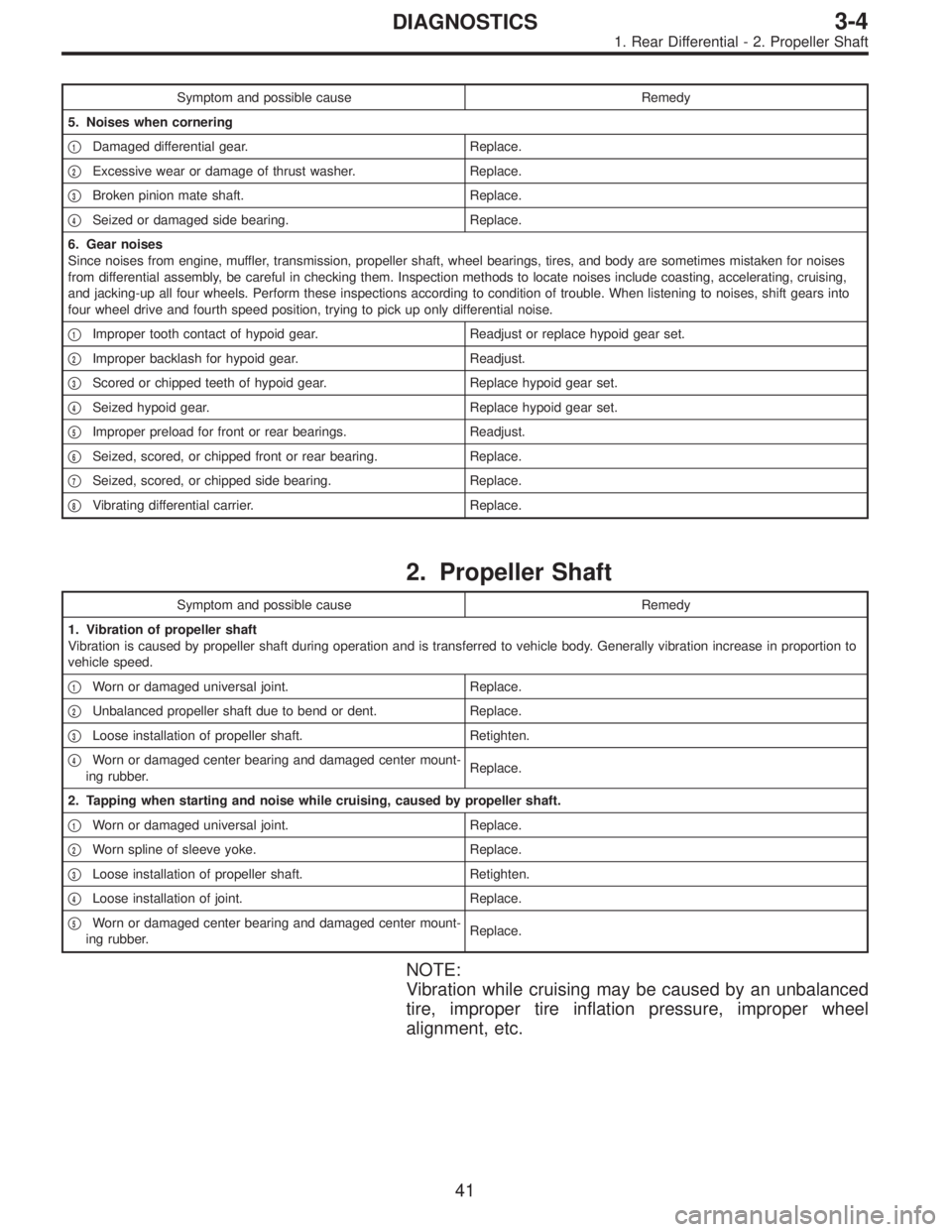
Symptom and possible cause Remedy
5. Noises when cornering
�
1Damaged differential gear. Replace.
�
2Excessive wear or damage of thrust washer. Replace.
�
3Broken pinion mate shaft. Replace.
�
4Seized or damaged side bearing. Replace.
6. Gear noises
Since noises from engine, muffler, transmission, propeller shaft, wheel bearings, tires, and body are sometimes mistaken for noises
from differential assembly, be careful in checking them. Inspection methods to locate noises include coasting, accelerating, cruising,
and jacking-up all four wheels. Perform these inspections according to condition of trouble. When listening to noises, shift gears into
four wheel drive and fourth speed position, trying to pick up only differential noise.
�
1Improper tooth contact of hypoid gear. Readjust or replace hypoid gear set.
�
2Improper backlash for hypoid gear. Readjust.
�
3Scored or chipped teeth of hypoid gear. Replace hypoid gear set.
�
4Seized hypoid gear. Replace hypoid gear set.
�
5Improper preload for front or rear bearings. Readjust.
�
6Seized, scored, or chipped front or rear bearing. Replace.
�
7Seized, scored, or chipped side bearing. Replace.
�
8Vibrating differential carrier. Replace.
2. Propeller Shaft
Symptom and possible cause Remedy
1. Vibration of propeller shaft
Vibration is caused by propeller shaft during operation and is transferred to vehicle body. Generally vibration increase in proportion to
vehicle speed.
�
1Worn or damaged universal joint. Replace.
�
2Unbalanced propeller shaft due to bend or dent. Replace.
�
3Loose installation of propeller shaft. Retighten.
�
4Worn or damaged center bearing and damaged center mount-
ing rubber.Replace.
2. Tapping when starting and noise while cruising, caused by propeller shaft.
�
1Worn or damaged universal joint. Replace.
�
2Worn spline of sleeve yoke. Replace.
�
3Loose installation of propeller shaft. Retighten.
�
4Loose installation of joint. Replace.
�
5Worn or damaged center bearing and damaged center mount-
ing rubber.Replace.
NOTE:
Vibration while cruising may be caused by an unbalanced
tire, improper tire inflation pressure, improper wheel
alignment, etc.
41
3-4DIAGNOSTICS
1. Rear Differential - 2. Propeller Shaft
Page 1080 of 3342

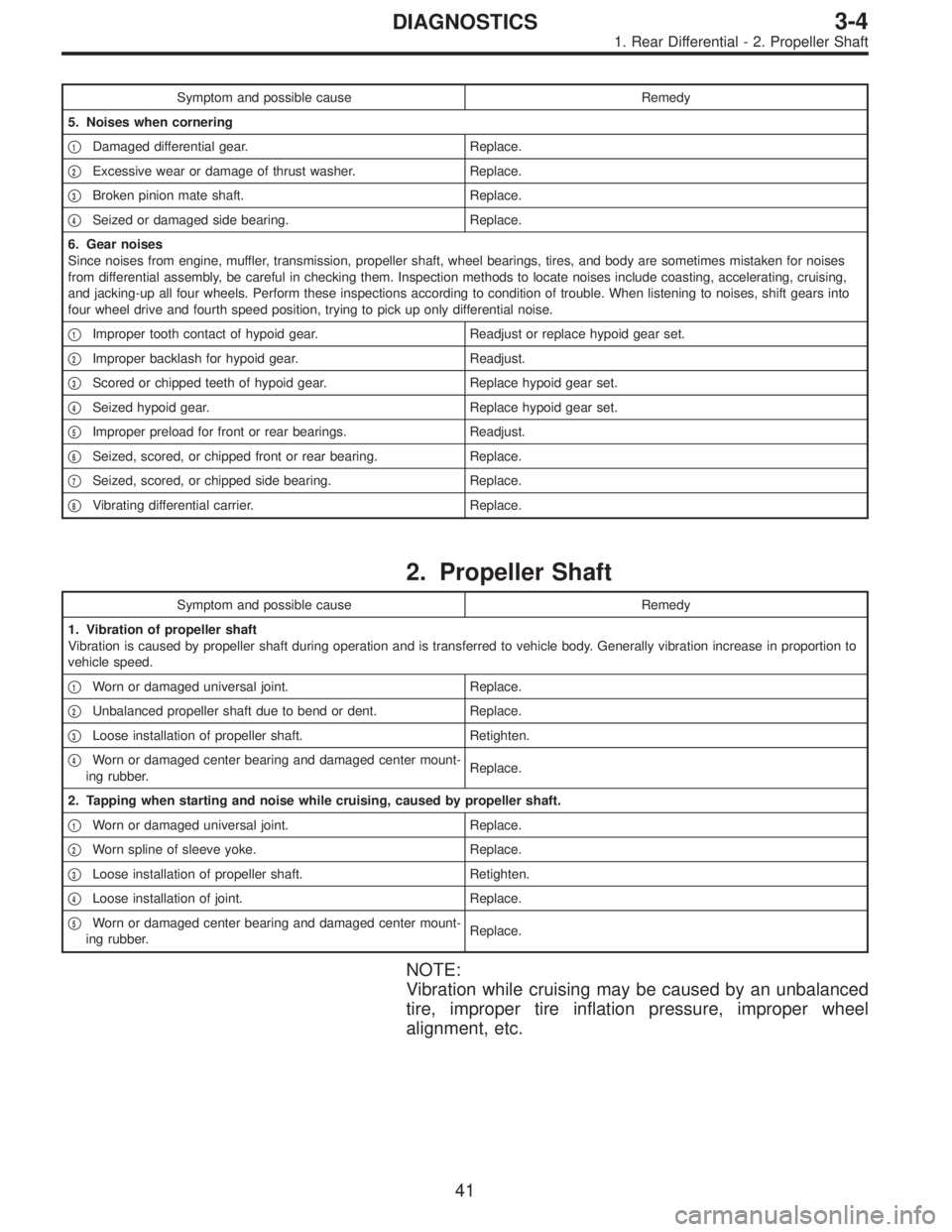
Symptom and possible cause Remedy
5. Noises when cornering
�
1Damaged differential gear. Replace.
�
2Excessive wear or damage of thrust washer. Replace.
�
3Broken pinion mate shaft. Replace.
�
4Seized or damaged side bearing. Replace.
6. Gear noises
Since noises from engine, muffler, transmission, propeller shaft, wheel bearings, tires, and body are sometimes mistaken for noises
from differential assembly, be careful in checking them. Inspection methods to locate noises include coasting, accelerating, cruising,
and jacking-up all four wheels. Perform these inspections according to condition of trouble. When listening to noises, shift gears into
four wheel drive and fourth speed position, trying to pick up only differential noise.
�
1Improper tooth contact of hypoid gear. Readjust or replace hypoid gear set.
�
2Improper backlash for hypoid gear. Readjust.
�
3Scored or chipped teeth of hypoid gear. Replace hypoid gear set.
�
4Seized hypoid gear. Replace hypoid gear set.
�
5Improper preload for front or rear bearings. Readjust.
�
6Seized, scored, or chipped front or rear bearing. Replace.
�
7Seized, scored, or chipped side bearing. Replace.
�
8Vibrating differential carrier. Replace.
2. Propeller Shaft
Symptom and possible cause Remedy
1. Vibration of propeller shaft
Vibration is caused by propeller shaft during operation and is transferred to vehicle body. Generally vibration increase in proportion to
vehicle speed.
�
1Worn or damaged universal joint. Replace.
�
2Unbalanced propeller shaft due to bend or dent. Replace.
�
3Loose installation of propeller shaft. Retighten.
�
4Worn or damaged center bearing and damaged center mount-
ing rubber.Replace.
2. Tapping when starting and noise while cruising, caused by propeller shaft.
�
1Worn or damaged universal joint. Replace.
�
2Worn spline of sleeve yoke. Replace.
�
3Loose installation of propeller shaft. Retighten.
�
4Loose installation of joint. Replace.
�
5Worn or damaged center bearing and damaged center mount-
ing rubber.Replace.
NOTE:
Vibration while cruising may be caused by an unbalanced
tire, improper tire inflation pressure, improper wheel
alignment, etc.
41
3-4DIAGNOSTICS
1. Rear Differential - 2. Propeller Shaft
Page 1636 of 3342

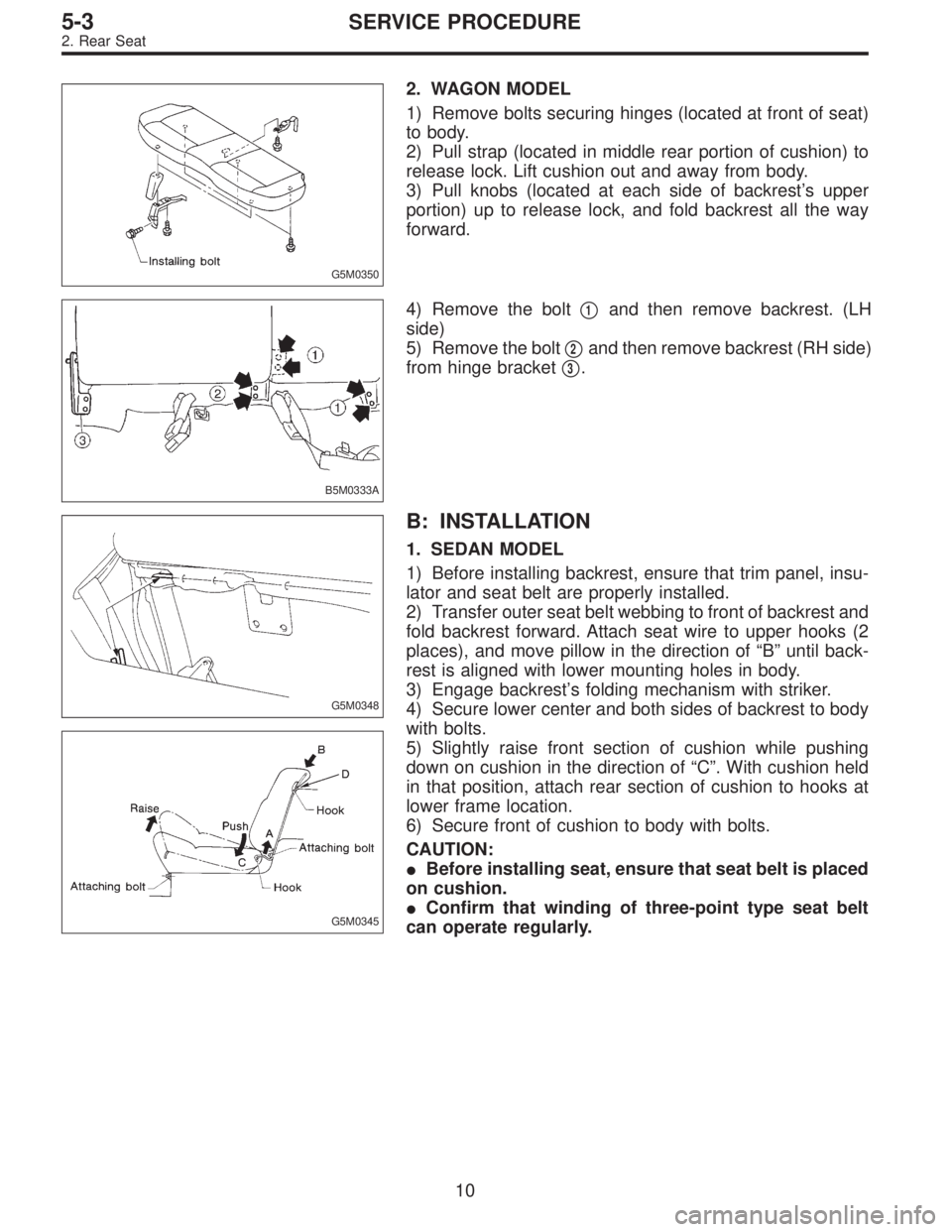
G5M0350
2. WAGON MODEL
1) Remove bolts securing hinges (located at front of seat)
to body.
2) Pull strap (located in middle rear portion of cushion) to
release lock. Lift cushion out and away from body.
3) Pull knobs (located at each side of backrest’s upper
portion) up to release lock, and fold backrest all the way
forward.
B5M0333A
4) Remove the bolt�1and then remove backrest. (LH
side)
5) Remove the bolt�
2and then remove backrest (RH side)
from hinge bracket�
3.
G5M0348
G5M0345
B: INSTALLATION
1. SEDAN MODEL
1) Before installing backrest, ensure that trim panel, insu-
lator and seat belt are properly installed.
2) Transfer outer seat belt webbing to front of backrest and
fold backrest forward. Attach seat wire to upper hooks (2
places), and move pillow in the direction of“B”until back-
rest is aligned with lower mounting holes in body.
3) Engage backrest’s folding mechanism with striker.
4) Secure lower center and both sides of backrest to body
with bolts.
5) Slightly raise front section of cushion while pushing
down on cushion in the direction of“C”. With cushion held
in that position, attach rear section of cushion to hooks at
lower frame location.
6) Secure front of cushion to body with bolts.
CAUTION:
�Before installing seat, ensure that seat belt is placed
on cushion.
�Confirm that winding of three-point type seat belt
can operate regularly.
10
5-3SERVICE PROCEDURE
2. Rear Seat
Page 1861 of 3342
B: AUTOMATIC TRANSMISSION
1. ELECTRONIC-HYDRAULIC CONTROL SYSTEM
The electronic-hydraulic control system consists of various
sensors and switches, a transmission control module
(TCM) and the hydraulic controller including solenoid
valves. The system controls the transmission proper
including shift control, lock-up control, overrunning clutch
control, line pressure control and shift timing control. It also
controls the AWD transfer clutch. In other words, the sys-
tem detects various operating conditions from various input
signals and sends output signals to shift solenoids 1, 2 and
3 and duty solenoids A, B and C (a total of six solenoids).
10
2-7ON-BOARD DIAGNOSTICS II SYSTEM
1. General
Page 1936 of 3342
A: BASIC CHECK ITEMS FOR AT
When trouble code about automatic transmission is shown
on display, carry out the following basic check. After that,
carry out the replacement or repair work.
1) ATF level check
2) Differential gear oil level check
3) ATF leak check
4) Differential gear oil leak check
5) Brake band adjustment
6) Stall test
7) Line pressure test
8) Transfer clutch pressure test
9) Time lag test
10) Road test
11) Shift characteristics
NOTE:
As for the method, refer to 3-2 [W2A0], [W2B1], [W300].
85
2-7ON-BOARD DIAGNOSTICS II SYSTEM
6. Basic Diagnostic Procedure