Page 2122 of 3342

1) Turn ignition switch to ON. (Engine OFF)
2) Measure voltage between ECM connector and chassis
ground.
: Co")
H2M1414B
10AZ3CHECK INPUT SIGNAL FOR ECM.
(USING VOLTAGE METER AND SUBARU
SELECT MONITOR.)
1) Turn ignition switch to ON. (Engine OFF)
2) Measure voltage between ECM connector and chassis
ground.
: Connector & terminal
(B84) No. 27 (+)—Chassis ground (�):
Is the voltage less than 0.12 V?
: Go to step10AZ4.
: Go to next.
H2M1327
: Does the value change less than 0.12 V by
shaking harness and connector of ECM
while monitoring the value with Subaru
Select Monitor?
�Subaru Select Monitor
Designate mode using function key.
Function mode: F45
�F45: Fuel level sensor output signal is indicated.
: Repair poor contact in ECM connector.
: Even if MIL lights up, the circuit has returned to a
normal condition at this time. A temporary poor
contact of the connector may be the cause.
NOTE:
In this case, repair the following:
�Poor contact in fuel pump connector
�Poor contact in combination meter connector
�Poor contact in ECM connector
�Poor contact in coupling connector (i3, B99, B22, B98
and R57)
G2M0340
10AZ4CHECK HARNESS BETWEEN ECM, COM-
BINATION METER AND FUEL PUMP
CONNECTOR.
1) Turn ignition switch to OFF.
2) Remove fuel pump access hole lid located on the right
rear of trunk compartment floor (Sedan) or luggage com-
partment floor (Wagon).
271
2-7ON-BOARD DIAGNOSTICS II SYSTEM
10. Diagnostic Chart with Trouble Code for LHD Vehicles
Page 2128 of 3342

1) Turn ignition switch to ON. (Engine OFF)
2) Measure voltage between ECM connector and chassis
ground.
: Co")
H2M1414B
10BA3CHECK INPUT SIGNAL FOR ECM.
(USING VOLTAGE METER AND SUBARU
SELECT MONITOR.)
1) Turn ignition switch to ON. (Engine OFF)
2) Measure voltage between ECM connector and chassis
ground.
: Connector & terminal
(B84) No. 27 (+)—Chassis ground (�):
Is the voltage more than 4.75 V?
: Go to step10BA4.
: Even if MIL lights up, the circuit has returned to a
normal condition at this time. A temporary poor
contact of the connector may be the cause.
NOTE:
In this case, repair the following:
�Poor contact in fuel pump connector
�Poor contact in combination meter connector
�Poor contact in ECM connector
�Poor contact in coupling connector (i3, B99, B22, B98
and R57)
G2M0340
10BA4
CHECK FUEL LEVEL SENSOR.
1) Turn ignition switch to OFF.
2) Remove fuel pump access hole lid located on the right
rear of trunk compartment floor (Sedan) or luggage com-
partment floor (Wagon).
B2M0935
3) Disconnect connector from fuel pump.
4) Measure resistance between connector terminals of
fuel pump.
: Terminals
No. 3—No. 5:
Is the resistance less than 100Ω?
: Go to step10BA5.
: Replace fuel sending unit.
G2M0863
10BA5
CHECK FUEL SUB LEVEL SENSOR.
1) Remove service hole cover located on the left rear of
trunk compartment floor (Sedan) or luggage compartment
floor (Wagon).
277
2-7ON-BOARD DIAGNOSTICS II SYSTEM
10. Diagnostic Chart with Trouble Code for LHD Vehicles
Page 2164 of 3342
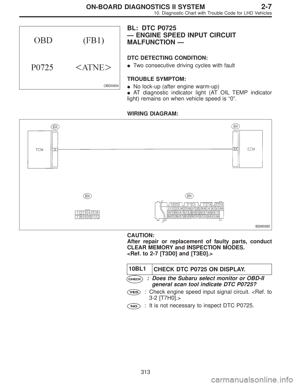
OBD0404
BL: DTC P0725
—ENGINE SPEED INPUT CIRCUIT
MALFUNCTION—
DTC DETECTING CONDITION:
�Two consecutive driving cycles with fault
TROUBLE SYMPTOM:
�No lock-up (after engine warm-up)
�AT diagnostic indicator light (AT OIL TEMP indicator
light) remains on when vehicle speed is“0”.
WIRING DIAGRAM:
B2M0585
CAUTION:
After repair or replacement of faulty parts, conduct
CLEAR MEMORY and INSPECTION MODES.
10BL1
CHECK DTC P0725 ON DISPLAY.
: Does the Subaru select monitor or OBD-II
general scan tool indicate DTC P0725?
: Check engine speed input signal circuit.
3-2 [T7H0].>
: It is not necessary to inspect DTC P0725.
313
2-7ON-BOARD DIAGNOSTICS II SYSTEM
10. Diagnostic Chart with Trouble Code for LHD Vehicles
Page 2170 of 3342
10BQ5CHECK VEHICLE SPEED SENSOR 2 CIR-
CUIT.
Check vehicle speed sensor 2 circuit.
: Is there any trouble in vehicle speed sensor
2 circuit?
: Repair or replace vehicle speed sensor 2 circuit.
: Go to step10BQ6.
10BQ6
CHECK ENGINE SPEED INPUT CIRCUIT.
Check engine speed input circuit.
: Is there any trouble in engine speed input
circuit?
: Repair or replace engine speed input circuit.
: Go to step10BQ7.
10BQ7
CHECK INHIBITOR SWITCH CIRCUIT.
Check inhibitor switch circuit.
: Is there any trouble in inhibitor switch cir-
cuit?
: Repair or replace inhibitor switch circuit.
: Go to step10BQ8.
10BQ8
CHECK BRAKE LIGHT SWITCH CIRCUIT.
Check brake light switch circuit.
: Is there any trouble in brake light switch cir-
cuit?
: Repair or replace brake light switch circuit.
: Go to step10BQ9.
319
2-7ON-BOARD DIAGNOSTICS II SYSTEM
10. Diagnostic Chart with Trouble Code for LHD Vehicles
Page 2220 of 3342
 Turn ignition switch to OFF.
2) Connect Subaru Select Monitor or the OBD-II general
scan tool to data link connector.
3) Turn ignition switch ON and Subaru Se")
OBD0145A
10CK1
CHECK DATA FOR CONTROL.
1) Turn ignition switch to OFF.
2) Connect Subaru Select Monitor or the OBD-II general
scan tool to data link connector.
3) Turn ignition switch ON and Subaru Select Monitor or
the OBD-II general scan tool switch ON.
4) Start engine.
5) Read data on Subaru Select Monitor or the OBD-II gen-
eral scan tool.
�Subaru Select Monitor
Designate mode using function key.
Function mode: F20
�F20: Display shows pressure signal value sent from the
pressure sensor.
B2M0755
: Is the value more than 133 kPa in function
mode F20?
: Replace pressure sensor.
: Even if MIL lights up, the circuit has returned to a
normal condition at this time. Contact with SOA
service.
NOTE:
Inspection by DTM is required, because probable cause is
deterioration of multiple parts.
�OBD-II general scan tool
For detailed operation procedures, refer to the OBD-II Gen-
eral Scan Tool Instruction Manual.
369
2-7ON-BOARD DIAGNOSTICS II SYSTEM
10. Diagnostic Chart with Trouble Code for LHD Vehicles
Page 2299 of 3342
 Turn ignition switch to OFF.
2) Connect Subaru Select Monitor or the OBD-II general
scan tool to data link")
B2M1016A
11V1CONNECT SUBARU SELECT MONITOR
OR THE OBD-II GENERAL SCAN TOOL,
AND READ DATA.
1) Turn ignition switch to OFF.
2) Connect Subaru Select Monitor or the OBD-II general
scan tool to data link connector.
3) Turn ignition switch to ON and Subaru Select Monitor or
OBD-II general scan tool switch to ON.
4) Start engine.
H2M1308
5) Read data on Subaru Select Monitor or OBD-II general
scan tool.
�Subaru Select Monitor
Designate mode using function key.
Function mode: F44
�F44: Fuel temperature is indicated in“°C”and“°F”.
: Is the value greater than 150°Cor300°Fin
function mode F44?
: Go to step11V2.
: Even if MIL lights up, the circuit has returned to a
normal condition at this time.
�OBD-II general scan tool
For detailed operation procedures, refer to the OBD-II Gen-
eral Scan Tool Instruction Manual.
G2M0340
11V2CHECK HARNESS BETWEEN FUEL TEM-
PERATURE SENSOR AND ECM CON-
NECTOR.
1) Turn ignition switch to OFF.
2) Remove access hole lid.
3) Disconnect connector from fuel pump.
B2M1016A
4) Connect Subaru Select Monitor or the OBD-II general
scan tool to data link connector.
5) Turn ignition switch and Subaru Select Monitor or
OBD-II general scan tool switch to ON.
448
2-7ON-BOARD DIAGNOSTICS II SYSTEM
11. Diagnostic Chart with Trouble Code for RHD Vehicles
Page 2339 of 3342

1) Turn ignition switch to ON. (Engine OFF)
2) Measure voltage between ECM connector and chassis
ground.
: Co")
H2M1414B
11AZ3CHECK INPUT SIGNAL FOR ECM.
(USING VOLTAGE METER AND SUBARU
SELECT MONITOR.)
1) Turn ignition switch to ON. (Engine OFF)
2) Measure voltage between ECM connector and chassis
ground.
: Connector & terminal
(B84) No. 27 (+)—Chassis ground (�):
Is the voltage less than 0.12 V?
: Go to step11AZ4.
: Go to next.
H2M1327
: Does the value change less than 0.12 V by
shaking harness and connector of ECM
while monitoring the value with Subaru
Select Monitor?
�Subaru Select Monitor
Designate mode using function key.
Function mode: F45
�F45: Fuel level sensor output signal is indicated.
: Repair poor contact in ECM connector.
: Even if MIL lights up, the circuit has returned to a
normal condition at this time. A temporary poor
contact of the connector may be the cause.
NOTE:
In this case, repair the following:
�Poor contact in fuel pump connector
�Poor contact in combination meter connector
�Poor contact in ECM connector
�Poor contact in coupling connector (i3, B22, B97 and
R57)
488
2-7ON-BOARD DIAGNOSTICS II SYSTEM
11. Diagnostic Chart with Trouble Code for RHD Vehicles
Page 2345 of 3342

1) Turn ignition switch to ON. (Engine OFF)
2) Measure voltage between ECM connector and chassis
ground.
: Co")
H2M1414B
11BA3CHECK INPUT SIGNAL FOR ECM.
(USING VOLTAGE METER AND SUBARU
SELECT MONITOR.)
1) Turn ignition switch to ON. (Engine OFF)
2) Measure voltage between ECM connector and chassis
ground.
: Connector & terminal
(B84) No. 27 (+)—Chassis ground (�):
Is the voltage more than 4.75 V?
: Go to step11BA4.
: Even if MIL lights up, the circuit has returned to a
normal condition at this time. A temporary poor
contact of the connector may be the cause.
NOTE:
In this case, repair the following:
�Poor contact in fuel pump connector
�Poor contact in combination meter connector
�Poor contact in ECM connector
�Poor contact in coupling connector (i3, B22, B97 and
R57)
G2M0340
11BA4
CHECK FUEL LEVEL SENSOR.
1) Turn ignition switch to OFF.
2) Remove fuel pump access hole lid located on the right
rear of luggage compartment floor.
B2M0935
3) Disconnect connector from fuel pump.
4) Measure resistance between connector terminals of
fuel pump.
: Terminals
No. 3—No. 5:
Is the resistance less than 100Ω?
: Go to step11BA5.
: Replace fuel sending unit.
G2M0863
11BA5
CHECK FUEL SUB LEVEL SENSOR.
1) Remove service hole cover located on the left rear of
luggage compartment floor.
494
2-7ON-BOARD DIAGNOSTICS II SYSTEM
11. Diagnostic Chart with Trouble Code for RHD Vehicles
![SUBARU LEGACY 1997 Service Repair Manual 10BQ5CHECK VEHICLE SPEED SENSOR 2 CIR-
CUIT.
Check vehicle speed sensor 2 circuit. <Ref. to 3-2 [T7M0].>
: Is there any trouble in vehicle speed sensor
2 circuit?
: Repair or replace vehicle speed sen](/manual-img/17/57434/w960_57434-2169.png "SUBARU LEGACY 1997 Service Repair Manual 10BQ5CHECK VEHICLE SPEED SENSOR 2 CIR-
CUIT.
Check vehicle speed sensor 2 circuit. <Ref. to 3-2 [T7M0].>
: Is there any trouble in vehicle speed sensor
2 circuit?
: Repair or replace vehicle speed sen")