Page 750 of 3342
4. CHECK FOR THE AWD FUNCTION
If“tight-corner braking”occurs when the steering wheel is
fully turned at low speed:
1) Determine the applicable trouble code and check the
corresponding duty solenoid C (transfer) for improper
operation.
2) If the solenoid is operating properly, check transfer
clutch pressure.
3) If oil pressure is normal but“tight-corner braking”
occurs:
Check the transfer control valve for sticking, and the trans-
fer clutch facing for wear.
44
3-2SERVICE PROCEDURE
3. Performance Test
Page 756 of 3342
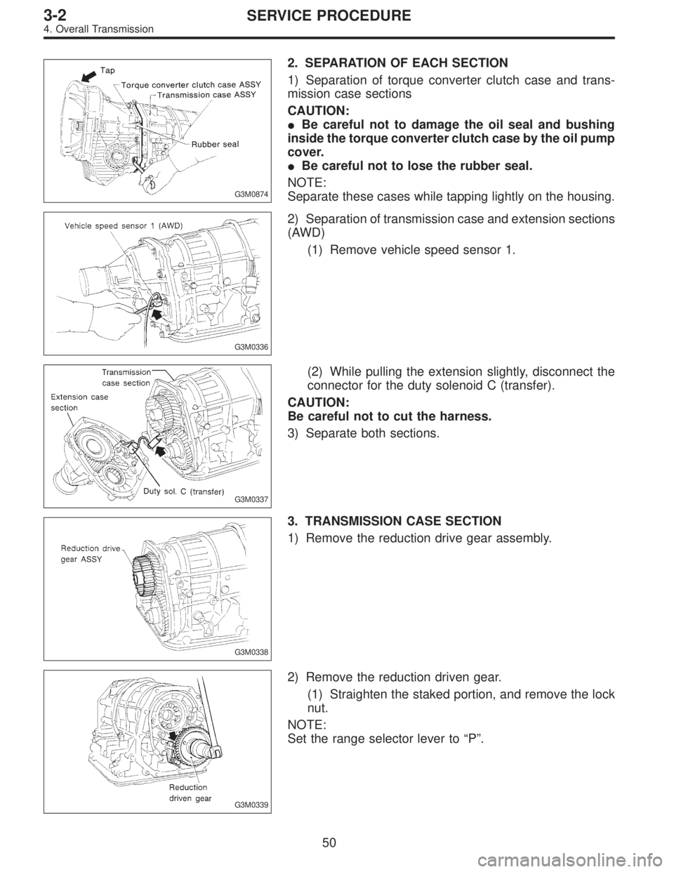
G3M0874
2. SEPARATION OF EACH SECTION
1) Separation of torque converter clutch case and trans-
mission case sections
CAUTION:
�Be careful not to damage the oil seal and bushing
inside the torque converter clutch case by the oil pump
cover.
�Be careful not to lose the rubber seal.
NOTE:
Separate these cases while tapping lightly on the housing.
G3M0336
2) Separation of transmission case and extension sections
(AWD)
(1) Remove vehicle speed sensor 1.
G3M0337
(2) While pulling the extension slightly, disconnect the
connector for the duty solenoid C (transfer).
CAUTION:
Be careful not to cut the harness.
3) Separate both sections.
G3M0338
3. TRANSMISSION CASE SECTION
1) Remove the reduction drive gear assembly.
G3M0339
2) Remove the reduction driven gear.
(1) Straighten the staked portion, and remove the lock
nut.
NOTE:
Set the range selector lever to“P”.
50
3-2SERVICE PROCEDURE
4. Overall Transmission
Page 764 of 3342
G3M0371
5) Remove the snap ring. Then remove the speedometer
driven gear.
G3M0372
6) Remove vehicle speed sensor 2.
7) Tap out the speedometer shaft to the outside of the
case, and remove the oil seal.
G3M0373
5. EXTENSION SECTION
1) Take out the transfer clutch by lightly tapping the end of
the rear drive shaft.
CAUTION:
Be careful not to damage the oil seal in the extension.
G3M0867
2) Remove duty solenoid C, transfer valve body and the
transfer pipe.
CAUTION:
�Take out the inlet filter.
�Do not damage the O-ring.
�Be careful not to bend the pipe.
B3M0831A
3) Take out the roller bearing inner race with ST.
ST 398527700 PULLER
4) Take out the roller bearing outer race with ST.
NOTE:
Hook ST in the inner side of the roller bearing outer race.
ST 398527700 PULLER
58
3-2SERVICE PROCEDURE
4. Overall Transmission
Page 782 of 3342
 Install the oil cooler outlet pipe, and secure with two
bolts.
Tightening torque:
8±1 N⋅m (0.8±0.1 kg-m, 5.8±0.7 ft-lb)
CAUTION:
Fit the pipe into position. Be careful to avoid twistin")
G3M0345
6) Install the oil cooler outlet pipe, and secure with two
bolts.
Tightening torque:
8±1 N⋅m (0.8±0.1 kg-m, 5.8±0.7 ft-lb)
CAUTION:
Fit the pipe into position. Be careful to avoid twisting.
G3M0427
7) Install the oil pan.
(1) Attach the magnet at the specified position.
G3M0428
(2) With gasket inserted, secure the oil pan by tighten-
ing 20 bolts.
Tightening torque:
4.9±0.5 N⋅m (0.50±0.05 kg-m, 3.6±0.4 ft-lb)
NOTE:
Tighten the bolts evenly.
G3M0867
5. EXTENSION SECTION
NOTE:
When installing new oil seal into extension case, press it
with ST.
ST 498057300 INSTALLER
1) Install the filter in the extension case.
NOTE:
Pay attention to the orientation of the filter.
2) Install the transfer clutch valve assembly, transfer pipe,
and the stay then secure with five bolts.
Tightening torque:
8±1 N⋅m (0.8±0.1 kg-m, 5.8±0.7 ft-lb)
CAUTION:
�Be sure to tighten the going lead with one of these
bolts.
�Be sure to use a new gasket.
76
3-2SERVICE PROCEDURE
4. Overall Transmission
Page 783 of 3342
 Install the transfer clutch assembly to the case.
CAUTION:
Be careful not to damage the seal rings.
NOTE:
Insert the clutch assembly fully into position until the bear-
ing shoulder bottoms")
G3M0894
3) Install the transfer clutch assembly to the case.
CAUTION:
Be careful not to damage the seal rings.
NOTE:
Insert the clutch assembly fully into position until the bear-
ing shoulder bottoms.
G3M0429
6. CONNECTION OF EACH SECTION
1) Install vehicle speed sensor 1 on transmission case.
[FWD only]
Tightening torque:
7±1 N⋅m (0.7±0.1 kg-m, 5.1±0.7 ft-lb)
2) Install oil pipe.
G3M0339
3) Install the reduction driven gear.
4) Install the parking pawl and shaft, set the select lever in
the“P”range and tighten the drive pinion lock nut.
Tightening torque:
98±5 N⋅m (10.0±0.5 kg-m, 72.3±3.6 ft-lb)
NOTE:
After tightening, stake the lock nut securely.
G3M0895
5) Install the reduction drive gear assembly.
CAUTION:
Align mark on reduction drive gear with mark on driven
gear during installation.
NOTE:
Insert it fully into position until the bearing shoulder bot-
toms.
G3M0430
6) Measurement and adjustment of extension end play
(1) Measure distance L from end of extension case and
rear drive shaft with ST. (On FWD models, measure
distance from end of case to point at bearing location.)
ST 398643600 GAUGE
Unit: mm
L = Measured value�15
77
3-2SERVICE PROCEDURE
4. Overall Transmission
Page 785 of 3342
 Installation of extension case (AWD), transmission
cover (FWD) and transmission case.
�AWD model:
(1) Attach the selected thrust needle bearing to the end
surface of reduction drive gear wi")
G3M0896
7) Installation of extension case (AWD), transmission
cover (FWD) and transmission case.
�AWD model:
(1) Attach the selected thrust needle bearing to the end
surface of reduction drive gear with vaseline.
(2) Set the parking return spring.
(3) Remove the transfer clutch from the extension
case.
Set the needle bearing on the reduction drive shaft and
then install transfer clutch to the transfer clutch hub.
NOTE:
Be sure to engage the spline teeth correctly.
(4) With gasket inserted between them, install the
extension case to the transmission case.
CAUTION:
�Be sure to use a new gasket.
�After inserting the extension case halfway, connect
the connector for duty solenoid C. Be careful not to
jam the cord in the case.
�Be careful not to damage the rear drive shaft seal
ring.
(5) Tighten bolts to secure the case.
Tightening torque:
25±2 N⋅m (2.5±0.2 kg-m, 18.1±1.4 ft-lb)
�FWD model:
(1) Attach selected shim to transmission cover using
vaseline.
(2) Set the parking return spring.
(3) After positioning gasket, assemble transmission
cover and transmission case.
NOTE:
While aligning bearings, parking shaft, reduction driven
gear, etc. assemble the two cases.
(4) Tighten bolts.
Tightening torque:
25±2 N⋅m (2.5±0.2 kg-m, 18.1±1.4 ft-lb)
G3M0336
7. EXTERNAL PARTS
1) Install the vehicle speed sensor 1. (AWD only)
Tightening torque:
7±1 N⋅m (0.7±0.1 kg-m, 5.1±0.7 ft-lb)
79
3-2SERVICE PROCEDURE
4. Overall Transmission
Page 815 of 3342
G3M0493
15. Transfer Clutch
A: DISASSEMBLY
1) Remove the seal ring.
CAUTION:
Be careful not to damage the seal ring.
G3M0494
2) Using a press and ST, remove the ball bearing.
ST 498077000 REMOVER
CAUTION:
Do not reuse the bearing.
G3M0495
3) Remove the snap ring, and take out the pressure plate,
drive plates, and driven plates.
G3M0496
4) Remove the snap ring with ST1, ST2 and ST3, and take
out the spring retainer.
ST1 399893600 PLIERS
ST2 398673600 COMPRESSOR
ST3 498627000 SEAT
G3M0497
5) Apply compressed air to the rear drive shaft to remove
the piston.
109
3-2SERVICE PROCEDURE
15. Transfer Clutch
Page 816 of 3342
 Check the drive plate facing for wear and damage.
2) Check the snap ring for wear, return spring for perma-
nent set and breakage, and spring retainer for deformation.
3) Check the la")
B: INSPECTION
1) Check the drive plate facing for wear and damage.
2) Check the snap ring for wear, return spring for perma-
nent set and breakage, and spring retainer for deformation.
3) Check the lathe cut ring for damage.
G3M0498
C: ASSEMBLY
1) Install the lathe cut seal ring to the I.D./O.D. of the
transfer clutch piston.
G3M0499
2) Install piston.
(1) Connect piston to rear drive shaft (until it reaches
hole in valve body).
(2) Install spring retainer to piston.
(3) Using ST1, ST2 and ST3, attach transfer piston
seal to ST2.
ST1 499247400 INSTALLER
ST2 499257400 PISTON GUIDE
ST3 498267400 TABLE
CAUTION:
Be careful not to tilt transfer piston seal.
G3M0500
(4) Place ST3 onto rear drive shaft so that spring can
be inserted into hole in transfer piston seal.
(5) Attach ST2 to rear drive shaft. Using ST1, press
into place.
ST1 499247400 INSTALLER
ST2 499257300 SNAP RING OUTER GUIDE
ST3 499257400 PISTON GUIDE
CAUTION:
Do not allow lip of transfer piston seal to fold back.
11 0
3-2SERVICE PROCEDURE
15. Transfer Clutch
 Determine the applicable trouble code and check the
corresponding duty solenoi")
 Remove the snap ring. Then remove the speedometer
driven gear.
G3M0372
6) Remove vehicle speed sensor 2.
7) Tap out the speedometer shaft to the outside of the
case, and remove the oil seal")
 Remove the seal ring.
CAUTION:
Be careful not to damage the seal ring.
G3M0494
2) Using a press and ST, remove the ball bearing.
ST 498077000 REMOVER
CAUT")