Page 171 of 3342
4-4d
[T1oYO]
BRAKES
[ABS
5
.3i
TYPE]
10
.
Diagnostics
Chart
with
Select
Monitor
D
"
NEW
44
(FBI)
CCM
LINE
B4M0964
Y
:
TROUBLE
CODE
44
CCM
LINE
-
A
COMBINATION
OF
AT
CONTROL
ABNORMALS
-
DIAGNOSIS
:
9
Combination
of
AT
control
faults
TROUBLE
SYMPTOM
:
9
ABS
does
not
operate
.
WIRING
DIAGRAM
:
F49
ABS
control
module
and
hydraulic
control
unit
Fuse
IGN
sw
SBF-4
FL1
.25B
No
.
16
f45B61B54
m
JE
O
~--I
1
1
Transmission
control
module
3100
B56
834855B56
1
44
1
4
910
1/16191
1
011
1
1121
191101
1
11121131141
1A
F49
123456789101112131415
16Y8"2
1819
ZO2
1
2324
5
2627
9
30
31
8100
f45
1
10
B4M1247
158
Page 174 of 3342
4-4d
[T1
0Z0]
BRAKES
[ABS
5
.31
TYPE]
10
.
Diagnostics
Chart
with
Select
Monitor
D
"
NEW
44
(FBI)
CCM
OPEN
B4M0965
Z
:
TROUBLE
CODE
44
CCM
OPEN
-
A
COMBINATIONOF
AT
CONTROL
ABNORMALS
-
DIAGNOSIS
:
9
Combination
of
AT
control
faults
TROUBLE
SYMPTOM
:
9
ABS
does
notoperate
.
WIRING
DIAGRAM
:
Fuse
IGN-1sw
SBF-4
FL1
.258
F49
ABS
control
module
and
hydraulic
control
unit
No
.
16
J
Ei
E
Transmission
control
module
3D100
P1
1213149161
1213141bl6l/lb
1
/1
b19liull
11121
19110111114131141A
glIZ11311411511611
/JIM
(~D
r--l
112131415161718191101llll2ll-3Fl4Tl-51
q
11611711811912012122
23
24
25
26
27
1
28
1
29
1
30
1
31
1
8100
F45
4=1
1161718-19
21131
1
41
1
10
B4M1247
I
162
Page 217 of 3342
WIRING
DIAGRAM
[osoa1
6-3
6
.
Wiring
Diagram
F2
100
Twisted
wire
LL
7
-
---
-
---------
-
FtP1
Transmission
control
module
Check
Data
link
connectorconnector
879
EEE
878
a
B56
:c
Ref
.
to
Engine
electrical
system
.
881
Diagnosis
PEterminal
B82
Q1
-
Diagnosis
connector
Front
~--~~
ABS
sensorLH
II
---------------
------_-----_--_----_J
Twisted
wire
ABS
G
sensor
86
B15
P8
(Outback
model
:
Brown)
O
(Other
models
:
Gray)
(Other
models)
(Outback
model)
(Gray)
86
Front
m--F-I
ABS
sensor
RH
n
(Outback
(Other
(Outback
(Other
model)
models)
model)
models)
RearABS
Rear
ABS
sensor
RH
sensor
LH
------------------
P11
1
01
P-am
B78
(Yellow)
879
(Gray)
F1
856
(Black)
1
4
1
4
56
10131
1
1
12131
45
6
8
10
56
88
99
10
111
1314
45678
1
11
1
12
1
13
1
14
1
15
1
16
11
/1
16
1
19
12U]
B82
(Black)
1
456
8100
(Blue)
4
6
171619
111
1
1415161
18192010BU82-04B
3
Page 460 of 3342

1. Engine Cooling System
Trouble Possible cause Corrective action
Over-heatinga. Insufficient engine coolantReplenish engine coolant, inspect for leakage, and
repair.
b. Loose timing belt Repair or replace timing belt tensioner.
c. Oil on drive belt Replace.
d. Malfunction of thermostat Replace.
e. Malfunction of engine coolant pump Replace.
f. Clogged engine coolant passage Clean.
g. Improper ignition timingInspect and repair ignition control system.
h. Clogged or leaking radiator Clean or repair, or replace.
i. Improper engine oil in engine coolant Replace engine coolant.
j. Air/fuel mixture ratio too leanInspect and repair fuel injection system.
k. Excessive back pressure in exhaust system Clean or replace.
l. Insufficient clearance between piston and cylinder Adjust or replace.
m. Slipping clutch Repair or replace.
n. Dragging brake Adjust.
o. Improper transmission oil Replace.
p. Defective thermostat Replace.
q. Malfunction of electric fanInspect radiator fan relay, engine coolant temperature
sensor or radiator motor and replace there.
Over-coolinga. Atmospheric temperature extremely low Partly cover radiator front area.
b. Defective thermostat Replace.
Engine coolant
leaks.a. Loosened or damaged connecting units on hoses Repair or replace.
b. Leakage from engine coolant pump Replace.
c. Leakage from engine coolant pipe Repair or replace.
d. Leakage around cylinder head gasket Retighten cylinder head bolts or replace gasket.
e. Damaged or cracked cylinder head and crankcase Repair or replace.
f. Damaged or cracked thermostat case Repair or replace.
g. Leakage from radiator Repair or replace.
Noisea. Defective drive belt Replace.
b. Defective radiator fan Replace.
c. Defective engine coolant pump bearing Replace engine coolant pump.
d. Defective engine coolant pump mechanical seal Replace engine coolant pump.
20
2-5DIAGNOSTICS
1. Engine Cooling System
Page 510 of 3342
G2M0434
2) Detach floor mat of front passenger seat.
3) Remove protect cover.
B2M0363
4) Release the lock of ECM connector and disconnect it.
5) Remove nuts which install ECM onto body.
6) Take out ECM.
B2M0364
7) Connect ECM connector and lock it.
8) Installation is in the reverse order of removal.
G6M0095
16. Main Relay
A: REMOVAL AND INSTALLATION
1) Disconnect battery ground cable.
B5M0024A
2) Remove lower cover and then disconnect connectors.
3) Lower transmission control module.
4) Remove the front pillar lower trim.
5) Remove fuse box mounting nuts.
6) Lower fuse box.
7) Remove fuse box mounting bracket.
32
2-7SERVICE PROCEDURE
15. Engine Control Module - 16. Main Relay
Page 511 of 3342
G2M0434
2) Detach floor mat of front passenger seat.
3) Remove protect cover.
B2M0363
4) Release the lock of ECM connector and disconnect it.
5) Remove nuts which install ECM onto body.
6) Take out ECM.
B2M0364
7) Connect ECM connector and lock it.
8) Installation is in the reverse order of removal.
G6M0095
16. Main Relay
A: REMOVAL AND INSTALLATION
1) Disconnect battery ground cable.
B5M0024A
2) Remove lower cover and then disconnect connectors.
3) Lower transmission control module.
4) Remove the front pillar lower trim.
5) Remove fuse box mounting nuts.
6) Lower fuse box.
7) Remove fuse box mounting bracket.
32
2-7SERVICE PROCEDURE
15. Engine Control Module - 16. Main Relay
Page 512 of 3342
G2M0438
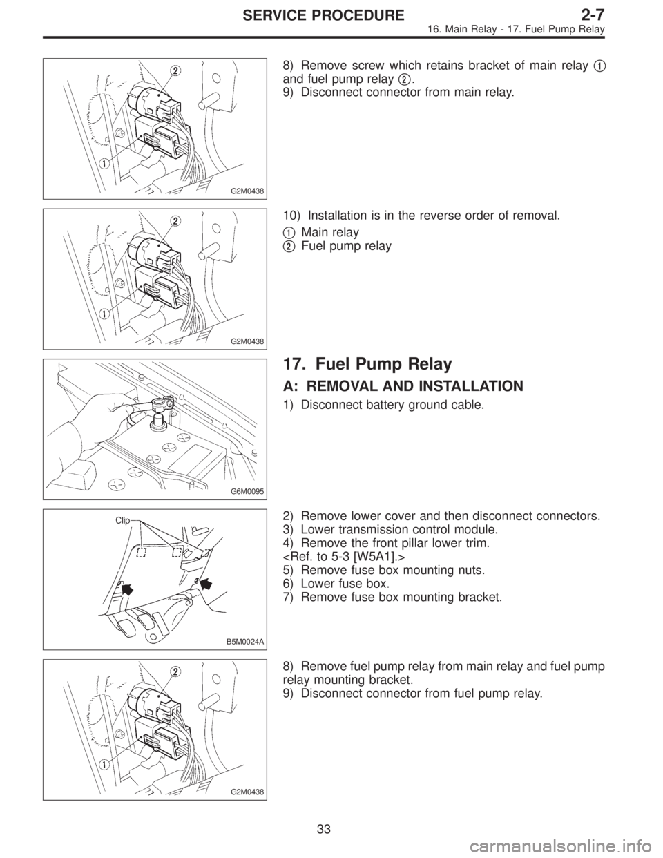
8) Remove screw which retains bracket of main relay�1
and fuel pump relay�2.
9) Disconnect connector from main relay.
G2M0438
10) Installation is in the reverse order of removal.
�
1Main relay
�
2Fuel pump relay
G6M0095
17. Fuel Pump Relay
A: REMOVAL AND INSTALLATION
1) Disconnect battery ground cable.
B5M0024A
2) Remove lower cover and then disconnect connectors.
3) Lower transmission control module.
4) Remove the front pillar lower trim.
5) Remove fuse box mounting nuts.
6) Lower fuse box.
7) Remove fuse box mounting bracket.
G2M0438
8) Remove fuel pump relay from main relay and fuel pump
relay mounting bracket.
9) Disconnect connector from fuel pump relay.
33
2-7SERVICE PROCEDURE
16. Main Relay - 17. Fuel Pump Relay
Page 513 of 3342
G2M0438
8) Remove screw which retains bracket of main relay�1
and fuel pump relay�2.
9) Disconnect connector from main relay.
G2M0438
10) Installation is in the reverse order of removal.
�
1Main relay
�
2Fuel pump relay
G6M0095
17. Fuel Pump Relay
A: REMOVAL AND INSTALLATION
1) Disconnect battery ground cable.
B5M0024A
2) Remove lower cover and then disconnect connectors.
3) Lower transmission control module.
4) Remove the front pillar lower trim.
5) Remove fuse box mounting nuts.
6) Lower fuse box.
7) Remove fuse box mounting bracket.
G2M0438
8) Remove fuel pump relay from main relay and fuel pump
relay mounting bracket.
9) Disconnect connector from fuel pump relay.
33
2-7SERVICE PROCEDURE
16. Main Relay - 17. Fuel Pump Relay
![SUBARU LEGACY 1997 Service Repair Manual
4-4d
[T1oYO]
BRAKES
[ABS
5
.3i
TYPE]
10
.
Diagnostics
Chart
with
Select
Monitor
D
"
NEW
44
(FBI)
CCM
LINE
B4M0964
Y
:
TROUBLE
CODE
44
CCM
LINE
-
A
COMBINATION
OF
AT
CONTROL
ABNORMALS
-
DI](/manual-img/17/57434/w960_57434-170.png "SUBARU LEGACY 1997 Service Repair Manual
4-4d
[T1oYO]
BRAKES
[ABS
5
.3i
TYPE]
10
.
Diagnostics
Chart
with
Select
Monitor
D
\"
NEW
44
(FBI)
CCM
LINE
B4M0964
Y
:
TROUBLE
CODE
44
CCM
LINE
-
A
COMBINATION
OF
AT
CONTROL
ABNORMALS
-
DI")
![SUBARU LEGACY 1997 Service Repair Manual
4-4d
[T1
0Z0]
BRAKES
[ABS
5
.31
TYPE]
10
.
Diagnostics
Chart
with
Select
Monitor
D
"
NEW
44
(FBI)
CCM
OPEN
B4M0965
Z
:
TROUBLE
CODE
44
CCM
OPEN
-
A
COMBINATIONOF
AT
CONTROL
ABNORMALS
-
DI](/manual-img/17/57434/w960_57434-173.png "SUBARU LEGACY 1997 Service Repair Manual
4-4d
[T1
0Z0]
BRAKES
[ABS
5
.31
TYPE]
10
.
Diagnostics
Chart
with
Select
Monitor
D
\"
NEW
44
(FBI)
CCM
OPEN
B4M0965
Z
:
TROUBLE
CODE
44
CCM
OPEN
-
A
COMBINATIONOF
AT
CONTROL
ABNORMALS
-
DI")

 Detach floor mat of front passenger seat.
3) Remove protect cover.
B2M0363
4) Release the lock of ECM connector and disconnect it.
5) Remove nuts which install ECM onto body.
6) Take out EC")
 Detach floor mat of front passenger seat.
3) Remove protect cover.
B2M0363
4) Release the lock of ECM connector and disconnect it.
5) Remove nuts which install ECM onto body.
6) Take out EC")