Page 220 of 3342
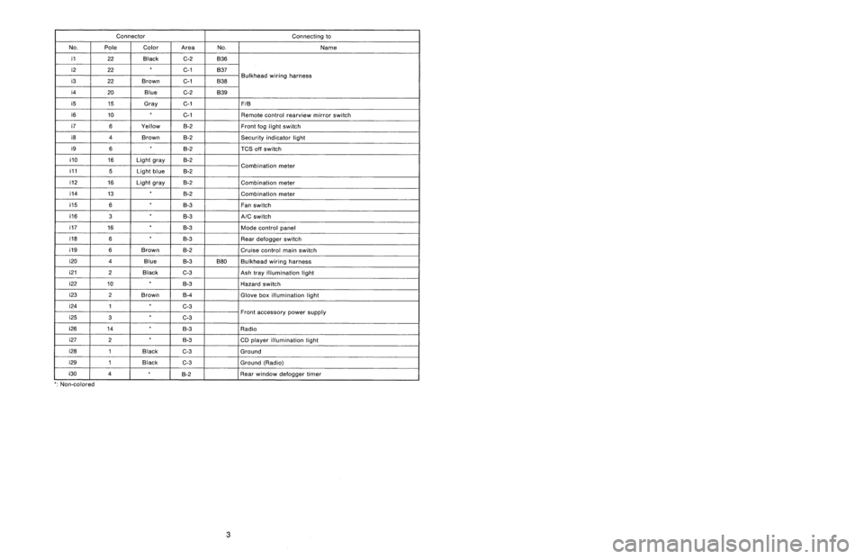
Connector
Connecting
to
No
.
Pole
Color
Area
No
.
Name
i1
22
Black
C-4
B36
i2
22
G4
B37
i3
22
Brown
C-4
B38
Bulkhead
wiring
harness
i4
20
Blue
C-4
B39
i5
15
Gray
C-4F!B
i6
10
C-4
Remote
control
rearview
mirror
switch
i10
16
Light
gray
B-3
i11
5
Light
blueB-3
Combination
meter
i12
16
Light
gray
B-3
Combination
meter
04
13
B-3
Combination
meter
05
6B-2
Fan
switch
07
16
Black
B-2
Mode
control
panel
08
6B-3
Rear
defogger
switch
09
6
Brown
B-3Cruise
control
main
switch
i20
4
Blue
B-2
B80
Bulkhead
wiring
harness
i22
10
B-2
Hazard
switch
i23
2
Brown
B-2
Glove
box
illumination
light
i24
1
G2
i25
3C-2Front
accessory
power
supply
i26
14
B-2
Radio
i27
2B-2
CD
player
illumination
light
i28
1
Black
C-2
Ground
i29
1
Black
C-2
Ground
(Radio)
i30
4B-2
Rear
window
defogger
timer
'
:
Non-colored
5
.
INSTRUMENT
PANEL
WIRING
HARNESS
AND
GROUND
POINT
9
RHD
model
1
23
AI
B
C
DI
1
2
3
5
Page 221 of 3342
Connector
Connecting
to
ole
Color
Area
No
.
Name
22
Black
C-4
B36
22
C-4
B37
lkh
ii
h
?2
Brown
C-4
B38
ead
w
r
ng
arness
Bu
20
Blue
C-4
B39
15
Gray
C-4
FIB
10
C-4
Remote
control
rearview
mirrorswitch
16
Light
gray
B-3
ii
5
Light
blue
B-3
Comb
nat
on
meter
16
Light
gray
B-3
Combination
meter
13
B-3
Combination
meter
6
B-2
Fan
switch
16
Black
B-2
Mode
control
panel
6
B-3
Rear
defogger
switch
6
Brown
B-3
Cruise
control
main
switch
4
Blue
B-2
B80
Bulkhead
wiring
harness
10
B-2
Hazard
switch
2
Brown
B-2
Glove
box
illumination
light
1
G2
F3
G2
ront
accessory
power
supply
14
8-2
Radio
2B-2
CD
player
illumination
light
1
Black
C-2
Ground
1
Black
G2
Ground
(Radio)
4
B-2
Rear
window
defogger
timer
5
.
INSTRUMENT
PANEL
WIRING
HARNESS
AND
GROUND
POINT
e
RHD
model
1
I
2
I
3
A
B
C
D
1
2
3
4
4
[D805]
B6M0849A
A
B
C
C
5
Page 222 of 3342

Connector
Connecting
to
No
.
Pole
Color
Area
No
.
Name
i1
22
Black
C-2
B36
i2
22C-1
B37
i3
22
Brown
C-1
B38
Bulkhead
wiring
harness
i4
20
Blue
C-2
B39
i5
15
Gray
C-1F1B
i6
10
C-1
Remote
control
rearview
mirrorswitch
i7
6
Yellow
B-2Front
fog
light
switch
i8
4
Brown
B-2Security
indicator
light
i9
6B-2
TCS
off
switch
i10
16
Light
gray
B-2
i11
5
Light
blueB-2
Combination
meter
i12
16
Light
gray
B-2
Combination
meter
i14
13
B-2
Combination
meter
05
6
B-3
Fan
switch
06
3
B-3
A/C
switch
07
16
B-3
Mode
control
panel
08
6B-3
Rear
defogger
switch
09
6
Brown
B-2
Cruise
control
main
switch
i20
4
Blue
B-3
B80
Bulkhead
wiring
harness
i212
Black
C-3
Ash
tray
illumination
light
i22
10
B-3
Hazard
switch
i23
2
Brown
B-4
Glove
box
illumination
light
i24
1
C-3
i25
3
C-3Front
accessory
power
supply
i26
14
B-3
Radio
i27
2B-3
CD
player
illumination
light
i28
1
Black
C-3
Ground
i29
1
Black
G3
Ground
(Radio)
i30
4
~
°
g-2
Rear
window
defogger
timer
'
:
Non-colored
8
.
Electrical
Wiring
Harness
and
Ground
Point
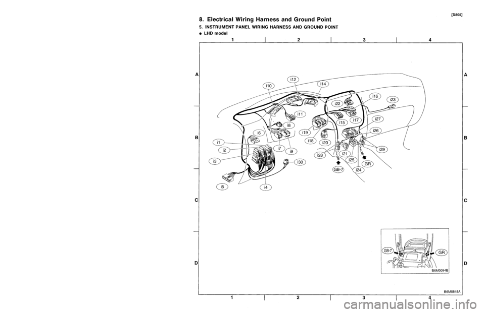
5
.
INSTRUMENT
PANEL
WIRING
HARNESS
AND
GROUND
POINT
9
LHD
model
1
23
A
B
CII
C
DI
3
1
23
Page 223 of 3342

Connector
Connecting
to
ole
Color
Area
No
.
Name
?2
Black
G2
B36
?2
C-1
B37
lkh
ii
h
?2
Brown
C-1
B38ead
w
r
ng
arness
Bu
?0
Blue
G-2
B39
15
Gray
C-1FIB
10
C-1
Remote
control
rearview
mirrorswitch
6
Yellow
B-2
Front
fog
light
switch
4
Brown
B-2Security
indicator
light
6B-2
TCS
off
switch
16
Light
gray
B-2
ii
5
Light
blueB-2
Comb
nat
on
meter
16
Light
gray
B-2
Combination
meter
13
~
B-2
Combination
meter
6B-3
Fan
switch
3B-3
A/C
switch
16
B-3
Mode
control
panel
6
B-3
Rear
defogger
switch
6
Brown
8-2Cruise
control
main
switch
4
Blue
B-3B80
Bulkhead
wiring
harness
?
Black
C-3
Ash
trayillumination
light
0
B-3
Hazard
switch
?
Brown
B-4
Glove
box
illumination
light
1
C-3
3
C-3Front
accessory
power
supply
4B-3
Radio
2
B-3
CD
player
illumination
light
I
Black
C-3
Ground
I
Black
C-3
Ground
(Radio)
B-2
~
~
Rear
window
defogger
timer
3
8
.
Electrical
Wiring
Harness
andGround
Point
5
.
INSTRUMENT
PANEL
WIRING
HARNESS
AND
GROUND
POINT
e
LHD
model
[D805]
1
I
2
I
3
A
B
C
1
2
3
4
4
B6M0848A
A
B
C
Page 1570 of 3342
![SUBARU LEGACY 1997 Service Repair Manual B5M0304
15. Roof Rack (Wagon only, if
equipped)
A: REMOVAL
1) Remove roof trim, rear quarter trim, pillar trim, etc.
<Ref. to 5-3 [W5A0].>
2) Remove flange bolts.
3) Remove flange nuts.
4) Remove roof SUBARU LEGACY 1997 Service Repair Manual B5M0304
15. Roof Rack (Wagon only, if
equipped)
A: REMOVAL
1) Remove roof trim, rear quarter trim, pillar trim, etc.
<Ref. to 5-3 [W5A0].>
2) Remove flange bolts.
3) Remove flange nuts.
4) Remove roof](/manual-img/17/57434/w960_57434-1569.png)
B5M0304
15. Roof Rack (Wagon only, if
equipped)
A: REMOVAL
1) Remove roof trim, rear quarter trim, pillar trim, etc.
2) Remove flange bolts.
3) Remove flange nuts.
4) Remove roof rail.
B: INSTALLATION
Installation is in the reverse order of removal.
CAUTION:
To prevent deformation, be sure to install roof rail in
steps 4), 3), 2) and 1), in that order.
B5M0307A
16. Sunroof
A: REMOVAL
1. GLASS LID ASSEMBLY
1) Completely open sun shade. (Push it back far.)
2) Remove a clip and detach guide rail cover.
3) Remove six nuts from the left and right lid bracket.
4) Working inside, slightly raise glass lid assembly until it
is disengaged from lid bracket.
5) Hold both ends of glass lid assembly and remove it at
an angle.
B5M0308B
2. SUNROOF MOTOR AND RELAY
1) Remove center pillar trim upper.
2) Remove front pillar trim upper.
3) Remove assist grip on left side.
4) Remove sunvisor with hook.
5) Remove sunroof switch.
6) Remove rearview mirror.
7) While rolling up roof trim, disconnect harness clips and
connector.
8) While rolling up roof trim, remove spot lamp bracket and
sunroof motor.
56
5-1SERVICE PROCEDURE
15. Roof Rack (Wagon only, if equipped) - 16. Sunroof
Page 1571 of 3342
![SUBARU LEGACY 1997 Service Repair Manual B5M0304
15. Roof Rack (Wagon only, if
equipped)
A: REMOVAL
1) Remove roof trim, rear quarter trim, pillar trim, etc.
<Ref. to 5-3 [W5A0].>
2) Remove flange bolts.
3) Remove flange nuts.
4) Remove roof SUBARU LEGACY 1997 Service Repair Manual B5M0304
15. Roof Rack (Wagon only, if
equipped)
A: REMOVAL
1) Remove roof trim, rear quarter trim, pillar trim, etc.
<Ref. to 5-3 [W5A0].>
2) Remove flange bolts.
3) Remove flange nuts.
4) Remove roof](/manual-img/17/57434/w960_57434-1570.png)
B5M0304
15. Roof Rack (Wagon only, if
equipped)
A: REMOVAL
1) Remove roof trim, rear quarter trim, pillar trim, etc.
2) Remove flange bolts.
3) Remove flange nuts.
4) Remove roof rail.
B: INSTALLATION
Installation is in the reverse order of removal.
CAUTION:
To prevent deformation, be sure to install roof rail in
steps 4), 3), 2) and 1), in that order.
B5M0307A
16. Sunroof
A: REMOVAL
1. GLASS LID ASSEMBLY
1) Completely open sun shade. (Push it back far.)
2) Remove a clip and detach guide rail cover.
3) Remove six nuts from the left and right lid bracket.
4) Working inside, slightly raise glass lid assembly until it
is disengaged from lid bracket.
5) Hold both ends of glass lid assembly and remove it at
an angle.
B5M0308B
2. SUNROOF MOTOR AND RELAY
1) Remove center pillar trim upper.
2) Remove front pillar trim upper.
3) Remove assist grip on left side.
4) Remove sunvisor with hook.
5) Remove sunroof switch.
6) Remove rearview mirror.
7) While rolling up roof trim, disconnect harness clips and
connector.
8) While rolling up roof trim, remove spot lamp bracket and
sunroof motor.
56
5-1SERVICE PROCEDURE
15. Roof Rack (Wagon only, if equipped) - 16. Sunroof
Page 1600 of 3342
B5M0068
8. OUTER HANDLE
1) Remove trim panel.
2) Remove sealing cover.
3) Detach door latch rod from outer handle and key lock.
4) Loosen nut securing outer handle and then remove
outer handle from outside.
CAUTION:
Be careful not to damage door.
Installation is in the reverse order of removal.
Tightening torque:
7.4±2.0 N⋅m (0.75±0.2 kg-m, 5.4±1.4 ft-lb)
B5M0069A
9. KEY LOCK
1) Remove trim panel.
2) Remove sealing cover.
3) Completely close door glass.
4) Remove outer handle.
5) Loosen spring�
1securing key lock.
6) Remove key lock from outer handle.
Installation is in the reverse order of removal.
NOTE:
Install so that key slot in key lock comes to center of hole
in outer handle.
B5M0070A
10. GUSSET
NOTE:
Be sure window is all the way down.
1) Remove trim panel.
2) Remove door rearview mirror.
3) Remove sealing cover.
4) Remove bolts and nuts which secure gusset.
5) Lift out gusset�
1.
To install, reverse the above removal procedures.
18
5-2SERVICE PROCEDURE
2. Door
Page 1623 of 3342

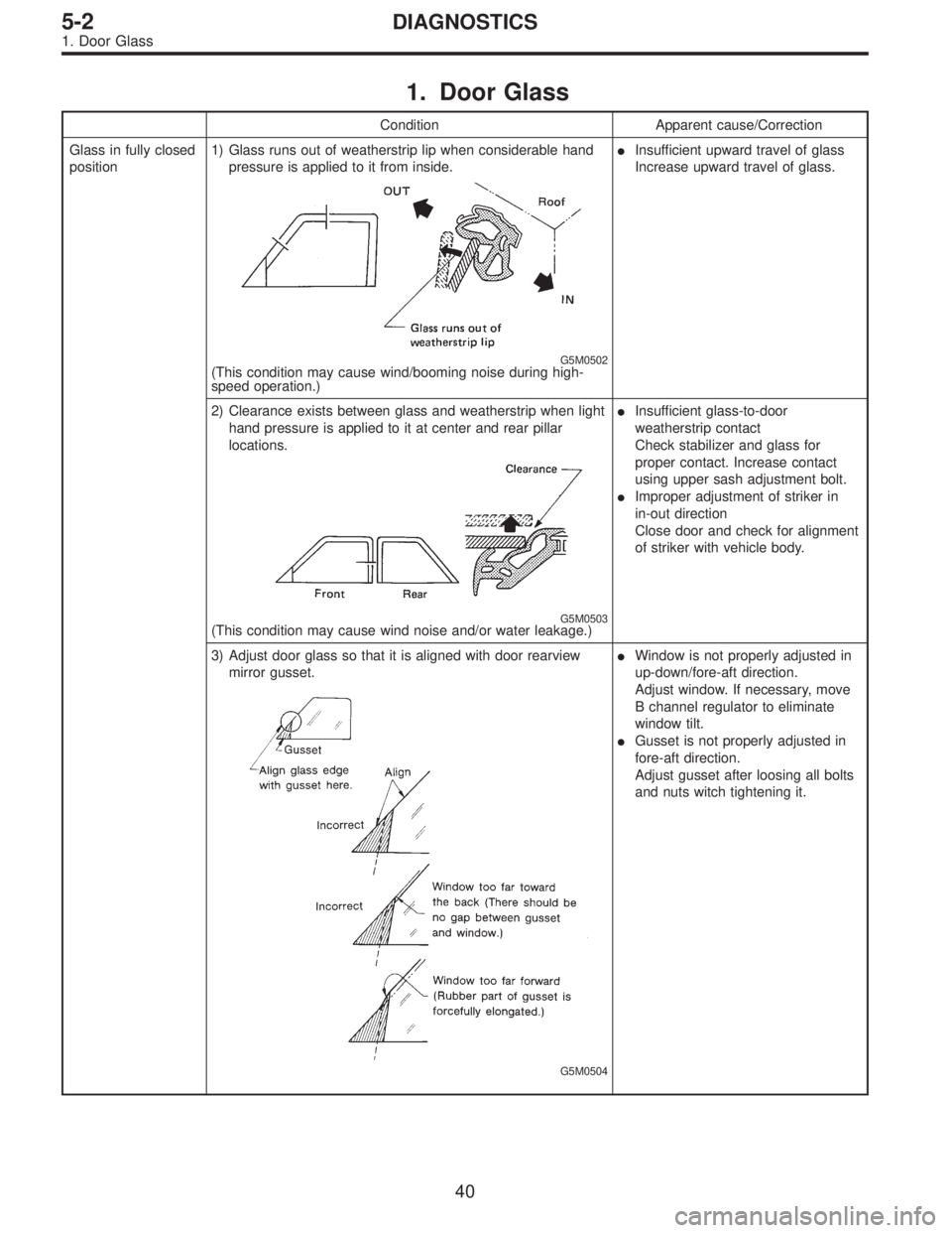
1. Door Glass
Condition Apparent cause/Correction
Glass in fully closed
position1) Glass runs out of weatherstrip lip when considerable hand
pressure is applied to it from inside.
G5M0502(This condition may cause wind/booming noise during high-
speed operation.)�Insufficient upward travel of glass
Increase upward travel of glass.
2) Clearance exists between glass and weatherstrip when light
hand pressure is applied to it at center and rear pillar
locations.
G5M0503(This condition may cause wind noise and/or water leakage.)�Insufficient glass-to-door
weatherstrip contact
Check stabilizer and glass for
proper contact. Increase contact
using upper sash adjustment bolt.
�Improper adjustment of striker in
in-out direction
Close door and check for alignment
of striker with vehicle body.
3) Adjust door glass so that it is aligned with door rearview
mirror gusset.
G5M0504
�Window is not properly adjusted in
up-down/fore-aft direction.
Adjust window. If necessary, move
B channel regulator to eliminate
window tilt.
�Gusset is not properly adjusted in
fore-aft direction.
Adjust gusset after loosing all bolts
and nuts witch tightening it.
40
5-2DIAGNOSTICS
1. Door Glass