1997 SSANGYONG KORANDO change time
[x] Cancel search: change timePage 1098 of 2053

5A-4 AUTOMATIC TRANSMISSION
SSANGYONG MY2002
Output circuits which control external devices such
as the Variable Pressure Solenoid (VPS) driver, On/
Off solenoid drivers, a diagnostics output and the
driving mode indicator light.
Processing Logic
Shift schedule and calibration information is stored in
an Erasable Programmable Read Only Memory (EPROM).
Throttle input calibration constants and the diagnostics
information are stored in Electrically Erasable Program-
mable Read Only Memory (EEPROM) that retains the
memory even when power to the TCM is disconnected.
TCM continuously monitors the input values and uses
these, via the shift schedule, to determine the required
gear state. At the same time it monitors, via the solenoid
outputs, the current gear state, whenever the input
conditions change such that the required gear state is
different to the current gear state, the TCM initiates a
gear shift to bring the two states back into line.
Once the TCM has determined the type of gearshift
required the TCM accesses the shift logic, estimates
the engine torque output, adjusts the variable pressure
solenoid ramp pressure then executes the shift.The TCM continuously monitors every input and output
circuit for short or open circuits and operating range.
When a failure or abnormal operation is detected the
TCM records the condition code in the diagnostics
memory and implements a Limp Home Mode (LHM).
The actual limp home mode used depends upon the
failure detected with the object to maintain maximum
drive-ability without damaging the transmission. In
general input failures are handled by providing a default
value. Output failures, which are capable of damaging
the transmission, result in full limp mode giving only
third or fourth gear and reverse. For further details of
limp modes and memory retention refer to the
Diagnostic Trouble Code Diagnosis Section.
The TCM is designed to operate at ambient
temperatures between - 40 and 85 °C (- 40 and 185 °F).
It is also protected against electrical noise and voltage
spikes, however all the usual precautions should be
observed, for example when arc welding or jump
starting.
TCM Inputs
To function correctly, the TCM requires engine speed,
vehicle speed, transmission fluid temperature, throttle
position, gear position and Kickdown Switch inputs to
determine the variable pressure solenoid current ramp
and on/off solenoid states.
KAA5A030
This ensures the correct gear selection and shift feel
for all driving conditions.
The inputs required by the TCM are as follows;
Page 1106 of 2053
5A-12 AUTOMATIC TRANSMISSION
SSANGYONG MY2002
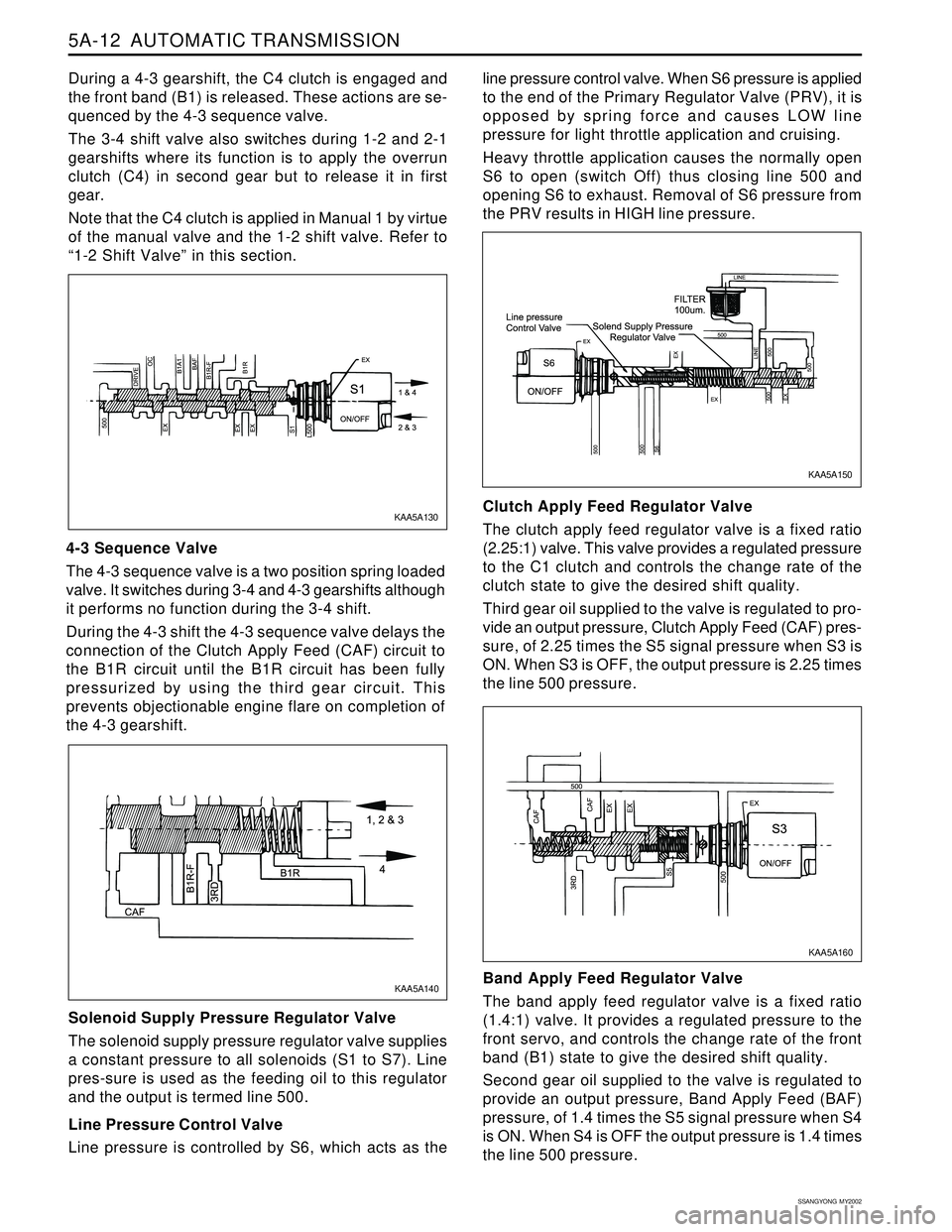
During a 4-3 gearshift, the C4 clutch is engaged and
the front band (B1) is released. These actions are se-
quenced by the 4-3 sequence valve.
The 3-4 shift valve also switches during 1-2 and 2-1
gearshifts where its function is to apply the overrun
clutch (C4) in second gear but to release it in first
gear.
Note that the C4 clutch is applied in Manual 1 by virtue
of the manual valve and the 1-2 shift valve. Refer to
“1-2 Shift Valve” in this section.
4-3 Sequence Valve
The 4-3 sequence valve is a two position spring loaded
valve. It switches during 3-4 and 4-3 gearshifts although
it performs no function during the 3-4 shift.
During the 4-3 shift the 4-3 sequence valve delays the
connection of the Clutch Apply Feed (CAF) circuit to
the B1R circuit until the B1R circuit has been fully
pressurized by using the third gear circuit. This
prevents objectionable engine flare on completion of
the 4-3 gearshift.
Solenoid Supply Pressure Regulator Valve
The solenoid supply pressure regulator valve supplies
a constant pressure to all solenoids (S1 to S7). Line
pres-sure is used as the feeding oil to this regulator
and the output is termed line 500.
Line Pressure Control Valve
Line pressure is controlled by S6, which acts as theline pressure control valve. When S6 pressure is applied
to the end of the Primary Regulator Valve (PRV), it is
opposed by spring force and causes LOW line
pressure for light throttle application and cruising.
Heavy throttle application causes the normally open
S6 to open (switch Off) thus closing line 500 and
opening S6 to exhaust. Removal of S6 pressure from
the PRV results in HIGH line pressure.
Clutch Apply Feed Regulator Valve
The clutch apply feed regulator valve is a fixed ratio
(2.25:1) valve. This valve provides a regulated pressure
to the C1 clutch and controls the change rate of the
clutch state to give the desired shift quality.
Third gear oil supplied to the valve is regulated to pro-
vide an output pressure, Clutch Apply Feed (CAF) pres-
sure, of 2.25 times the S5 signal pressure when S3 is
ON. When S3 is OFF, the output pressure is 2.25 times
the line 500 pressure.
Band Apply Feed Regulator Valve
The band apply feed regulator valve is a fixed ratio
(1.4:1) valve. It provides a regulated pressure to the
front servo, and controls the change rate of the front
band (B1) state to give the desired shift quality.
Second gear oil supplied to the valve is regulated to
provide an output pressure, Band Apply Feed (BAF)
pressure, of 1.4 times the S5 signal pressure when S4
is ON. When S4 is OFF the output pressure is 1.4 times
the line 500 pressure.
KAA5A160 KAA5A130
KAA5A150
KAA5A140
Page 1151 of 2053
5A-56 AUTOMATIC TRANSMISSION
SSANGYONG MY2002
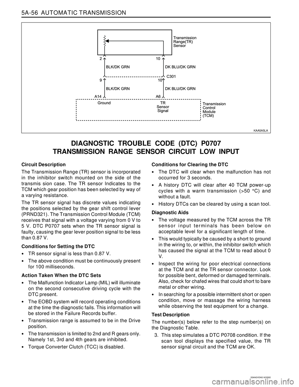
Circuit Description
The Transmission Range (TR) sensor is incorporated
in the inhibitor switch mounted on the side of the
transmis sion case. The TR sensor Indicates to the
TCM which gear position has been selected by way of
a varying resistance.
The TR sensor signal has discrete values indicating
the positions selected by the gear shift control lever
(PRND321). The Transmission Control Module (TCM)
receives that signal with a voltage varying from 0 V to
5 V. DTC P0707 sets when the TR sensor signal is
faulty, causing the gear lever position signal to be less
than 0.87 V.
Conditions for Setting the DTC
TR sensor signal is less than 0.87 V.
The above condition must be continuously present
for 100 milliseconds.
Action Taken When the DTC Sets
The Malfunction Indicator Lamp (MIL) will illuminate
on the second consecutive driving cycle with the
DTC present.
The EOBD system will record operating conditions
at the time the diagnostic fails. This information will
be stored in the Failure Records buffer.
Transmission range is assumed to be in the Drive
position.
The transmission is limited to 2nd and R gears only.
Namely 1st, 3rd and 4th gears are inhibited.
Torque Converter Clutch (TCC) is disabled.
DIAGNOSTIC TROUBLE CODE (DTC) P0707
TRANSMISSION RANGE SENSOR CIRCUIT LOW INPUT
Conditions for Clearing the DTC
The DTC will clear when the malfunction has not
occurred for 3 seconds.
A history DTC will clear after 40 TCM power-up
cycles with a warm transmission (>50 °C) and
without a fault.
History DTCs can be cleared by using a scan tool.
Diagnostic Aids
The voltage measured by the TCM across the TR
sensor input terminals has been below on
acceptable level for a significant length of time.
This would typically be caused by a short to ground
in the wiring to, or within, the inhibitor switch which
has caused the signal at the TCM to read about 0
V.
Inspect the wiring for poor electrical connections
at the TCM and at the TR sensor connector. Look
for possible bent, deformed or damaged terminals.
Also, check for chafed wires that could short to bare
metal or other wiring.
In searching for a possible intermittent short or open
condition, move or massage the wiring harness
while observing the test equipment for a change.
Test Description
The number(s) below refer to the step number(s) on
the Diagnostic Table.
3. This step simulates a DTC P0708 condition. If the
scan tool displays the specified value, the TR
sensor signal circuit and the TCM are OK.
KAA5A5LA
Page 1153 of 2053
5A-58 AUTOMATIC TRANSMISSION
SSANGYONG MY2002
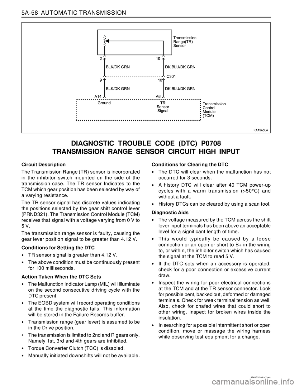
Circuit Description
The Transmission Range (TR) sensor is incorporated
in the inhibitor switch mounted on the side of the
transmission case. The TR sensor Indicates to the
TCM which gear position has been selected by way of
a varying resistance.
The TR sensor signal has discrete values indicating
the positions selected by the gear shift control lever
(PRND321). The Transmission Control Module (TCM)
receives that signal with a voltage varying from 0 V to
5 V.
The transmission range sensor is faulty, causing the
gear lever position signal to be greater than 4.12 V.
Conditions for Setting the DTC
TR sensor signal is greater than 4.12 V.
The above condition must be continuously present
for 100 milliseconds.
Action Taken When the DTC Sets
The Malfunction Indicator Lamp (MIL) will illuminate
on the second consecutive driving cycle with the
DTC present.
The EOBD system will record operating conditions
at the time the diagnostic fails. This information
will be stored in the Failure Records buffer.
Transmission range (gear lever) is assumed to be
in the Drive position.
The transmission is limited to 2nd and R gears only.
Namely 1st, 3rd and 4th gears are inhibited.
Torque Converter Clutch (TCC) is disabled.
Manually initiated downshifts will not be available.
DIAGNOSTIC TROUBLE CODE (DTC) P0708
TRANSMISSION RANGE SENSOR CIRCUIT HIGH INPUT
Conditions for Clearing the DTC
The DTC will clear when the malfunction has not
occurred for 3 seconds.
A history DTC will clear after 40 TCM power-up
cycles with a warm transmission (>50°C) and
without a fault.
History DTCs can be cleared by using a scan tool.
Diagnostic Aids
The voltage measured by the TCM across the shift
lever input terminals has been above an acceptable
level for a significant length of time.
This would typically be caused by a loose
connection or an open or short to B+ in the wiring
to, or within, the inhibitor switch which has caused
the signal at the TCM to read 5 V.
If the DTC sets when an accessory is operated,
check for a poor connection or excessive current
draw.
Inspect the wiring for poor electrical connections
at the TCM and at the TR sensor connector. Look
for possible bent, backed out, deformed or damaged
terminals. Check for weak terminal tension as well.
Also, check for chafed wires that could short to
other wiring. Inspect for broken wires inside the
insulation.
In searching for a possible intermittent short or open
condition, move or massage the wiring harness
while observing test equipment for a change.
KAA5A5LA
Page 1161 of 2053
5A-66 AUTOMATIC TRANSMISSION
SSANGYONG MY2002
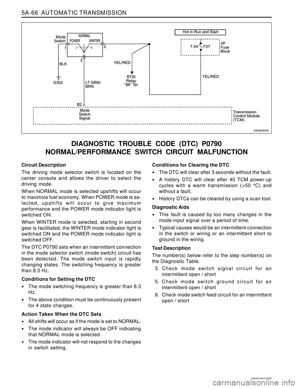
Circuit Description
The driving mode selector switch is located on the
center console and allows the driver to select the
driving mode.
When NORMAL mode is selected upshifts will occur
to maximize fuel economy. When POWER mode is se-
lected, upshifts will occur to give maximum
performance and the POWER mode indicator light is
switched ON.
When WINTER mode is selected, starting in second
gear is facilitated, the WINTER mode indicator light is
switched ON and the POWER mode indicator light is
switched OFF.
The DTC P0790 sets when an intermittent connection
in the mode selector switch (mode switch) circuit has
been detected. The mode switch input is rapidly
changing states. The switching frequency is greater
than 8.3 Hz.
Conditions for Setting the DTC
The mode switching frequency is greater than 8.3
Hz.
The above condition must be continuously present
for 4 state changes.
Action Taken When the DTC Sets
All shifts will occur as if the mode is set to NORMAL.
The mode indicator will always be OFF indicating
that NORMAL mode is selected.
The mode indicator will not respond to the changes
in switch setting.
DIAGNOSTIC TROUBLE CODE (DTC) P0790
NORMAL/PERFORMANCE SWITCH CIRCUIT MALFUNCTION
Conditions for Clearing the DTC
The DTC will clear after 3 seconds without the fault.
A history DTC will clear after 40 TCM power-up
cycles with a warm transmission (>50 °C) and
without a fault.
History DTCs can be cleared by using a scan tool.
Diagnostic Aids
This fault is caused by too many changes in the
mode input signal over a period of time.
Typical causes would be an intermittent connection
in the switch or wiring or an intermittent short to
ground in the wiring.
Test Description
The number(s) below refer to the step number(s) on
the Diagnostic Table.
3. Check mode switch signal circuit for an
intermittent open / short
5. Check mode switch ground circuit for an
intermittent open / short
8. Check mode switch feed circuit for an intermittent
open / short
KAA5A5NA
Page 1167 of 2053
5A-72 AUTOMATIC TRANSMISSION
SSANGYONG MY2002
Circuit Description
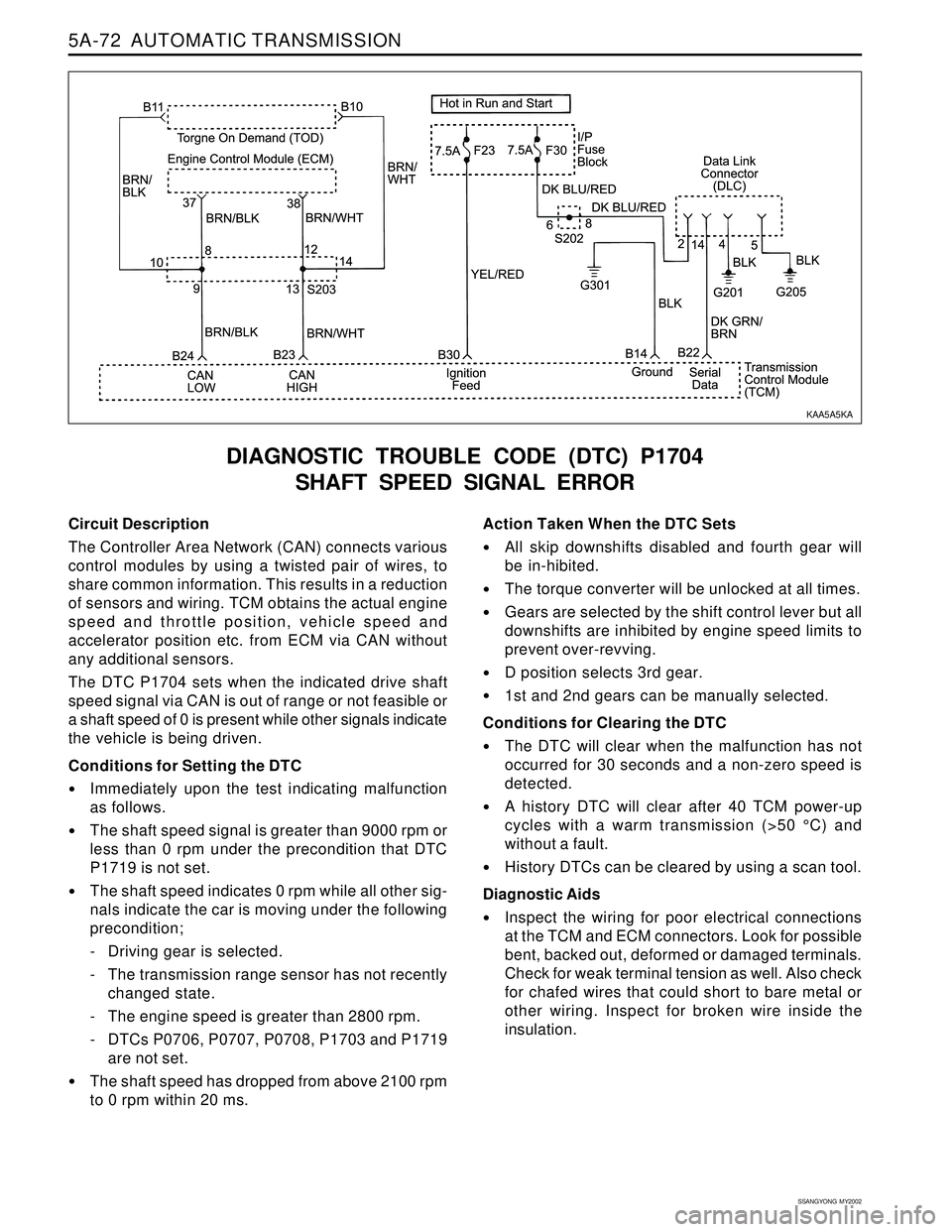
The Controller Area Network (CAN) connects various
control modules by using a twisted pair of wires, to
share common information. This results in a reduction
of sensors and wiring. TCM obtains the actual engine
speed and throttle position, vehicle speed and
accelerator position etc. from ECM via CAN without
any additional sensors.
The DTC P1704 sets when the indicated drive shaft
speed signal via CAN is out of range or not feasible or
a shaft speed of 0 is present while other signals indicate
the vehicle is being driven.
Conditions for Setting the DTC
Immediately upon the test indicating malfunction
as follows.
The shaft speed signal is greater than 9000 rpm or
less than 0 rpm under the precondition that DTC
P1719 is not set.
The shaft speed indicates 0 rpm while all other sig-
nals indicate the car is moving under the following
precondition;
- Driving gear is selected.
- The transmission range sensor has not recently
changed state.
- The engine speed is greater than 2800 rpm.
- DTCs P0706, P0707, P0708, P1703 and P1719
are not set.
The shaft speed has dropped from above 2100 rpm
to 0 rpm within 20 ms.
DIAGNOSTIC TROUBLE CODE (DTC) P1704
SHAFT SPEED SIGNAL ERROR
Action Taken When the DTC Sets
All skip downshifts disabled and fourth gear will
be in-hibited.
The torque converter will be unlocked at all times.
Gears are selected by the shift control lever but all
downshifts are inhibited by engine speed limits to
prevent over-revving.
D position selects 3rd gear.
1st and 2nd gears can be manually selected.
Conditions for Clearing the DTC
The DTC will clear when the malfunction has not
occurred for 30 seconds and a non-zero speed is
detected.
A history DTC will clear after 40 TCM power-up
cycles with a warm transmission (>50 °C) and
without a fault.
History DTCs can be cleared by using a scan tool.
Diagnostic Aids
Inspect the wiring for poor electrical connections
at the TCM and ECM connectors. Look for possible
bent, backed out, deformed or damaged terminals.
Check for weak terminal tension as well. Also check
for chafed wires that could short to bare metal or
other wiring. Inspect for broken wire inside the
insulation.
KAA5A5KA
Page 1173 of 2053
5A-78 AUTOMATIC TRANSMISSION
SSANGYONG MY2002
Circuit Description
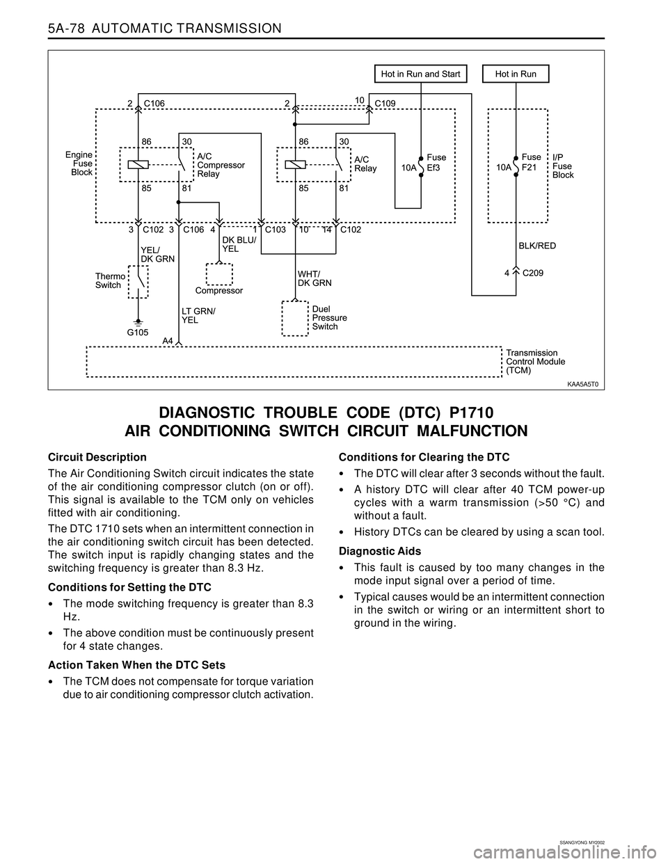
The Air Conditioning Switch circuit indicates the state
of the air conditioning compressor clutch (on or off).
This signal is available to the TCM only on vehicles
fitted with air conditioning.
The DTC 1710 sets when an intermittent connection in
the air conditioning switch circuit has been detected.
The switch input is rapidly changing states and the
switching frequency is greater than 8.3 Hz.
Conditions for Setting the DTC
The mode switching frequency is greater than 8.3
Hz.
The above condition must be continuously present
for 4 state changes.
Action Taken When the DTC Sets
The TCM does not compensate for torque variation
due to air conditioning compressor clutch activation.
DIAGNOSTIC TROUBLE CODE (DTC) P1710
AIR CONDITIONING SWITCH CIRCUIT MALFUNCTION
Conditions for Clearing the DTC
The DTC will clear after 3 seconds without the fault.
A history DTC will clear after 40 TCM power-up
cycles with a warm transmission (>50 °C) and
without a fault.
History DTCs can be cleared by using a scan tool.
Diagnostic Aids
This fault is caused by too many changes in the
mode input signal over a period of time.
Typical causes would be an intermittent connection
in the switch or wiring or an intermittent short to
ground in the wiring.
KAA5A5T0
Page 1189 of 2053
5A-94 AUTOMATIC TRANSMISSION
SSANGYONG MY2002
Circuit Description
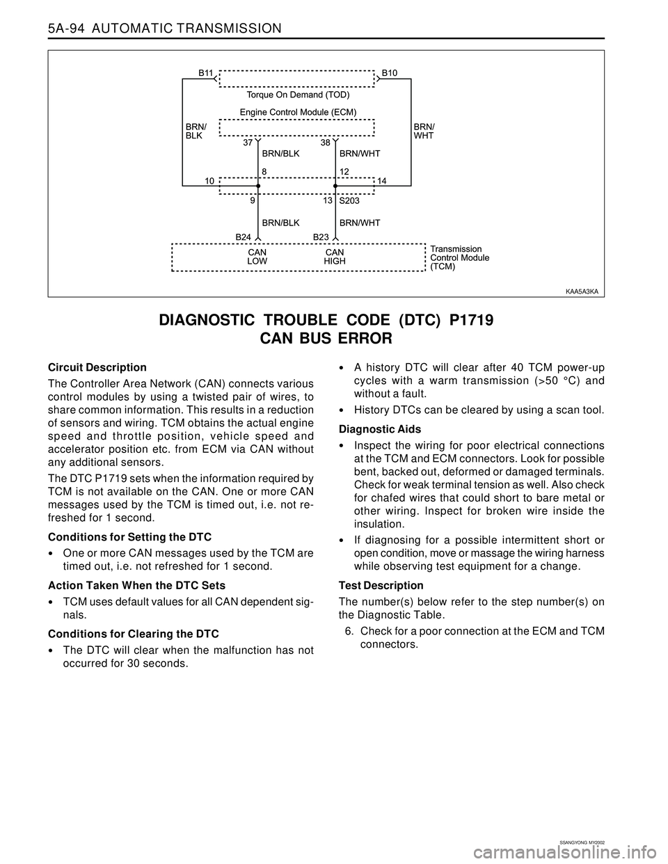
The Controller Area Network (CAN) connects various
control modules by using a twisted pair of wires, to
share common information. This results in a reduction
of sensors and wiring. TCM obtains the actual engine
speed and throttle position, vehicle speed and
accelerator position etc. from ECM via CAN without
any additional sensors.
The DTC P1719 sets when the information required by
TCM is not available on the CAN. One or more CAN
messages used by the TCM is timed out, i.e. not re-
freshed for 1 second.
Conditions for Setting the DTC
One or more CAN messages used by the TCM are
timed out, i.e. not refreshed for 1 second.
Action Taken When the DTC Sets
TCM uses default values for all CAN dependent sig-
nals.
Conditions for Clearing the DTC
The DTC will clear when the malfunction has not
occurred for 30 seconds.
DIAGNOSTIC TROUBLE CODE (DTC) P1719
CAN BUS ERROR
A history DTC will clear after 40 TCM power-up
cycles with a warm transmission (>50 °C) and
without a fault.
History DTCs can be cleared by using a scan tool.
Diagnostic Aids
Inspect the wiring for poor electrical connections
at the TCM and ECM connectors. Look for possible
bent, backed out, deformed or damaged terminals.
Check for weak terminal tension as well. Also check
for chafed wires that could short to bare metal or
other wiring. Inspect for broken wire inside the
insulation.
If diagnosing for a possible intermittent short or
open condition, move or massage the wiring harness
while observing test equipment for a change.
Test Description
The number(s) below refer to the step number(s) on
the Diagnostic Table.
6. Check for a poor connection at the ECM and TCM
connectors.
KAA5A3KA