Page 1063 of 2053

SSANGYONG MY2002
4F-80 ABS AND TCS
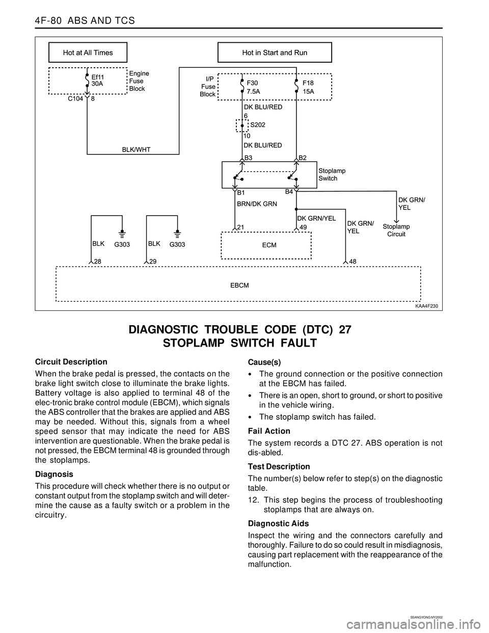
DIAGNOSTIC TROUBLE CODE (DTC) 27
STOPLAMP SWITCH FAULT
KAA4F230
Circuit Description
When the brake pedal is pressed, the contacts on the
brake light switch close to illuminate the brake lights.
Battery voltage is also applied to terminal 48 of the
elec-tronic brake control module (EBCM), which signals
the ABS controller that the brakes are applied and ABS
may be needed. Without this, signals from a wheel
speed sensor that may indicate the need for ABS
intervention are questionable. When the brake pedal is
not pressed, the EBCM terminal 48 is grounded through
the stoplamps.
Diagnosis
This procedure will check whether there is no output or
constant output from the stoplamp switch and will deter-
mine the cause as a faulty switch or a problem in the
circuitry.Cause(s)
The ground connection or the positive connection
at the EBCM has failed.
There is an open, short to ground, or short to positive
in the vehicle wiring.
The stoplamp switch has failed.
Fail Action
The system records a DTC 27. ABS operation is not
dis-abled.
Test Description
The number(s) below refer to step(s) on the diagnostic
table.
12. This step begins the process of troubleshooting
stoplamps that are always on.
Diagnostic Aids
Inspect the wiring and the connectors carefully and
thoroughly. Failure to do so could result in misdiagnosis,
causing part replacement with the reappearance of the
malfunction.
Page 1075 of 2053
SSANGYONG MY2002
4F-92 ABS AND TCS
ABS / TCS CIRCUIT (2 OF 2): GASOLINE - STOP LAMP SWITCH,
DECELERATION SENSOR, WHEEL SPEED SENSOR DIAGNOSIS
KAA4F270
Page 1077 of 2053
SSANGYONG MY2002
4F-94 ABS AND TCS
ABS / ABD (AUTOMATIC BRAKE DIFFERENTIAL LOCK):
DIESEL - STOPLAMP SWITCH, ACCELERATION SENSOR, WHEEL SPEED SENSOR DIAGNOSIS
KAA4F290
Page 1078 of 2053
ABS AND TCS 4F-95
SSANGYONG MY2002
EBCM CONNECTION FACE VIEW
(WITHOUT TRACTION CONTROL SYSTEM)
EBCM CONNECTOR
KAA4F300
Color
BLK/DK GRN
BRN/BLK
-
BRN/WHT
BRN/BLK
BLK/RED
BRN/RED
BRN/YEL
BLK/DK GRN
YEL
BRN/DK GRN
-
RED/YEL
DK GRN/YEL
WHT/RED
BLK Pin
1
2
3
4
5
6
7
8
9
10
11
12
13
14
15
16Circuit
Right Rear Ground
Right Rear Sensor
Not Used
Right Front Ground
Right Front Sensor
Left Front Ground
Left Front Sensor
Left Rear Ground
Left Rear Sensor
Acceleration Sensor
Signal Voltage
Data Link Connector
Not Used
Torque On Demand
Stoplamp Switch
Ignition
GroundColor
RED/WHT
RED/WHT
-
BLK
LT GRN
DK GRN/BRN
-
-
-
-
-
RED
-
DK BLU
- Pin
17
18
19
20
21
22
23
24
25
26
27
28
29
30
31Circuit
Battery
Battery
Ground
ABS Warning Lamp
EBD Warning Lamp
Not Used
Not Used
Not Used
Not Used
Not Used
Not Used
Acceleration Sensor
Supply Voltage
Not Used
Acceleration Sensor
Ground
Not Used
Page 1080 of 2053

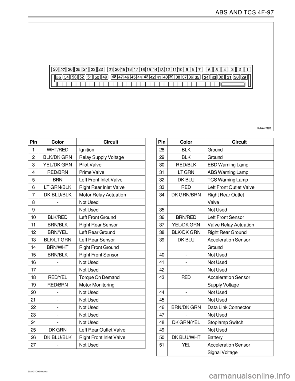
ABS AND TCS 4F-97
SSANGYONG MY2002
KAA4F320
Color
WHT/RED
BLK/DK GRN
YEL/DK GRN
RED/BRN
BRN
LT GRN/BLK
DK BLU/BLK
-
-
BLK/RED
BRN/BLK
BRN/YEL
BLK/LT GRN
BRN/WHT
BRN/BLK
-
-
RED/YEL
RED/BRN
-
-
-
-
-
DK GRN
DK BLU/BLK
- Pin
1
2
3
4
5
6
7
8
9
10
11
12
13
14
15
16
17
18
19
20
21
22
23
24
25
26
27Circuit
Ignition
Relay Supply Voltage
Pilot Valve
Prime Valve
Left Front Inlet Valve
Right Rear Inlet Valve
Motor Relay Actuation
Not Used
Not Used
Left Front Ground
Right Rear Sensor
Left Rear Ground
Left Rear Sensor
Right Front Ground
Right Front Sensor
Not Used
Not Used
Torque On Demand
Motor Monitoring
Not Used
Not Used
Not Used
Not Used
Not Used
Left Rear Outlet Valve
Right Front Inlet Valve
Not UsedColor
BLK
BLK
RED/BLK
LT GRN
DK BLU
RED
DK GRN/BRN
-
BRN/RED
YEL/DK GRN
BLK/DK GRN
DK BLU
-
-
-
RED
-
-
BRN/DK GRN
-
DK GRN/YEL
-
DK BLU/WHT
YEL Pin
28
29
30
31
32
33
34
35
36
37
38
39
40
41
42
43
44
45
46
47
48
49
50
51Circuit
Ground
Ground
EBD Warning Lamp
ABS Warning Lamp
TCS Warning Lamp
Left Front Outlet Valve
Right Rear Outlet
Valve
Not Used
Left Front Sensor
Valve Relay Actuation
Right Rear Ground
Acceleration Sensor
Ground
Not Used
Not Used
Not Used
Acceleration Sensor
Supply Voltage
Not Used
Not Used
Data Link Connector
Not Used
Stoplamp Switch
Not Used
Battery
Acceleration Sensor
Signal Voltage
Page 1084 of 2053

ABS AND TCS 4F-101
SSANGYONG MY2002
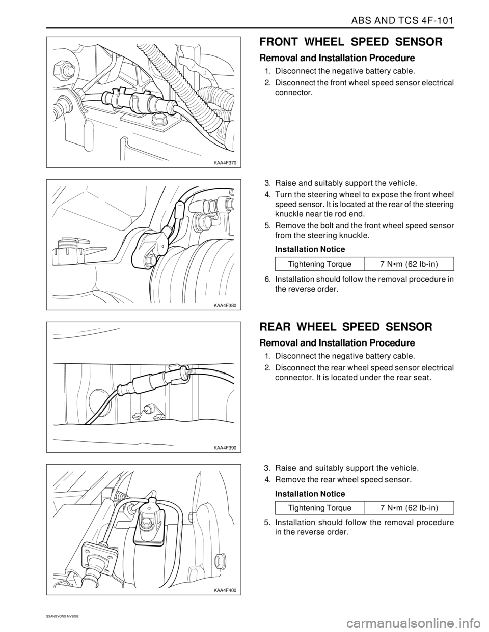
FRONT WHEEL SPEED SENSOR
Removal and Installation Procedure
1. Disconnect the negative battery cable.
2. Disconnect the front wheel speed sensor electrical
connector.
3. Raise and suitably support the vehicle.
4. Turn the steering wheel to expose the front wheel
speed sensor. It is located at the rear of the steering
knuckle near tie rod end.
5. Remove the bolt and the front wheel speed sensor
from the steering knuckle.
Installation Notice
KAA4F370
KAA4F380
Tightening Torque 7 Nm (62 lb-in)
6. Installation should follow the removal procedure in
the reverse order.
REAR WHEEL SPEED SENSOR
Removal and Installation Procedure
1. Disconnect the negative battery cable.
2. Disconnect the rear wheel speed sensor electrical
connector. It is located under the rear seat.
3. Raise and suitably support the vehicle.
4. Remove the rear wheel speed sensor.
Installation Notice
KAA4F390
KAA4F400
Tightening Torque 7 Nm (62 lb-in)
5. Installation should follow the removal procedure
in the reverse order.
Page 1085 of 2053
SSANGYONG MY2002
4F-102 ABS AND TCS
ACCELERATION SENSOR
Removal and Installation Procedure
1. Disconnect the negative battery cable.
2. Disconnect the acceleration sensor connector. It
is located at the rear of audio system.
3. Remove the acceleration sensor mounting bolts.
Installation Notice
SYSTEM FUSE
Removal and Installation Procedure
The ABS/TCS system fuse, EF11, is located in the
engine fuse block. Counting from the battery toward
the surge tank, it is the first system fuse in the row.
KAA4F410
KAA4F420
Tightening Torque 7 Nm (62 lb-in)
4. Installation should follow the removal procedure in
the reverse order.
INDICATORS
The indicator lamps ABS and EBD and TCS are part of
the instrument cluster. Refer to Section 9E, instrumenta-
tion/ Driver information, for removal and replacement
details.
Page 1097 of 2053

AUTOMATIC TRANSMISSION 5A-3
SSANGYONG MY2002
N - Neutral allows the engine to be started and oper-
ated while driving the vehicle. The inhibitor switch
allows the engine to be started. There is no power
transferred through the transmission in Neutral. But
the final drive is not locked by the parking pawl, so
thewheels are free to rotate.
D - Overdrive range is used for all normal driving
conditions. 4th gear (overdrive gear) reduces the
fuel consumption and the engine noise. Engine
braking is applied with reduced throttle.
First to second (1 → 2), first to third (1 → 3), second
to third (2 → 3), second to fourth (2 → 4), third to
fourth (3 → 4), fourth to third (4 → 3), fourth to
second (4 → 2), third to second (3 → 2), third to
first (3 → 1) and second to first (2 → 1) shifts are
all available as a function of vehicle speed, throttle
position and the time change rate of the throttle
position.
Downshifts are available for safe passing by
depress-ing the accelerator. Lockup clutch may be
enabled in 3rd and 4th gears depending on vehicle
type.
3 - Manual 3 provides three gear ratios (first through
third) and prevents the transmission from operating
in 4th gear. 3rd gear is used when driving on long
hill roads or in heavy city traffic. Downshifts are
available by depressing the accelerator.
2 - Manual 2 provides two gear ratios (first and
second). It is used to provide more power when
climbing hills or engine braking when driving down
a steep hill or starting off on slippery roads.
1 - Manual 1 is used to provide the maximum engine
braking when driving down the severe gradients.When NORMAL mode is selected upshifts will occur
to maximize fuel economy. When POWER mode is se-
lected, upshifts will occur to give maximum
performance and the POWER mode indicator light is
switched ON.
When WINTER mode is selected, starting in second
gear is facilitated, the WINTER mode indicator light is
switched ON and the POWER mode indicator light is
switched OFF.
Indicator Light
The indicator light is located on the instrument panel.
Auto shift indicator light comes ON when the ignition
switch ON and shows the gear shift control lever
position.
POWER mode indicator light comes ON when the
POWER mode is selected and when the kickdown
switch is depressed.
WINTER mode indicator light comes ON when the
WINTER mode is selected.
CONTROL SYSTEMS
BTRA M74 4WD automatic transmission consists of
two control systems. One is the electronic control
system that monitors vehicle parameters and adjusts
the transmission performance. Another is the hydraulic
control system that implements the commands of the
electronic control system commands.
ELECTRONIC CONTROL SYSTEM
The electronic control system comprises of sensors, a
TCM and seven solenoids. The TCM reads the inputs
and activates the outputs according to values stored
in Read Only Memory (ROM).
The TCM controls the hydraulic control system. This
control is via the hydraulic valve body, which contains
seven electromagnetic solenoids. Six of the seven
solenoids are used to control the line pressure, operate
the shift valves and the torque converter lock-up clutch,
and to turn ON and OFF the two regulator valves that
control the shift feel.
The seventh solenoid is the proportional or Variable
Pressure Solenoid (VPS) which works with the two regu-
lator valves to control shift feel.
Transmission Control Module (TCM)
The TCM is an in-vehicle micro-processor based trans-
mission management system. It is mounted under the
driver’s side front seat in the vehicle cabin.
The TCM contains:
Processing logic circuits which include a central mi-
croprocessor controller and a back-up memory
system.
Input circuits.
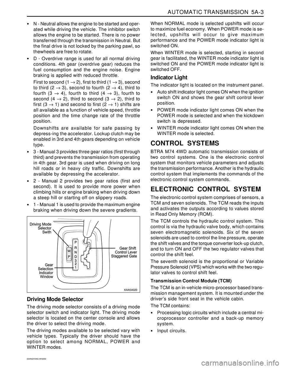
Driving Mode Selector
The driving mode selector consists of a driving mode
selector switch and indicator light. The driving mode
selector is located on the center console and allows
the driver to select the driving mode.
The driving modes available to be selected vary with
vehicle types. Typically the driver should have the
option to select among NORMAL, POWER and
WINTER modes.
KAA5A020