Page 154 of 2053
1E 1 -- 2 M162 ENGINE ELECTRICAL
D AEW OO M Y_2000
SPECIFICATIONS
GENERATOR SPECIFICATIONS
ApplicationDescription
Current11 5 A
Output Voltage12 -- 14 v
Resistance Between Rotor Core and Slip Ring∞Ω
STARTER SPECIFICATIONS
ApplicationDescription
Output Power1.8 kw
Voltage12 v
BATTERY SPECIFICATIONS
ApplicationDescription
Capacity90 AH
Max. Tolerance Between Cells≥0.04
Specific Gravity≥1.24
FASTER TIGHTENING SPECIFICATIONS
ApplicationNSmLb-FtLb-In
Generator Terminal B+Nut14 -- 1810 -- 13--
Generator Terminal D+Nut4--5--35 -- 44
Generator Mounting Bolt2518--
Battery Cable Nut on Starting Motor12 -- 159--11--
Electric Wire Nut on Starting Motor6--7--53 -- 62
Starting Motor Mounting Bolt35 -- 4826 -- 35--
Battery Mounting Bracket Nut12 -- 189--13--
Battery Negative Cable12 -- 189--13--
Battery Positive Cable12 -- 189--13--
Spark Plug Cover Bolt9--11--80 -- 97
Ignition Cable Bolt9--11--80 -- 97
Spark plug20 -- 3015 -- 22--
Page 155 of 2053
M162 ENGINE ELECTRICAL 1E 1 -- 3
D AEW OO M Y_2000
MAINTENANCE AND REPAIR
ON-VEHICLE SERVICE
GENERATOR
Preceding Work : Removal of the drivebelt
Removal & Installation Procedure
1. Disconnect the negative battery terminal.
2. Unscrew the nut and disconnect the terminal (1).
Installation Notice
Tightening Torque
14 -- 18 NSm (10 -- 13 lb-ft)
3. Unscrew the nut and disconnect the terminal (2).
Installation Notice
Tightening Torque
4--5NSm (35 -- 44 lb-in)
1 Terminal (B+)
2 Terminal (D+)
4. Unscrew the generator mounting bolt (3).
Installation Notice
Tightening Torque
25 NSm (18 lb-ft)
5. Remove the generator.
6. Installation should follow the removal procedure in
the reverse order.
3 Generator Mounting Bolt
4 Generator
Page 156 of 2053
1E 1 -- 4 M162 ENGINE ELECTRICAL
D AEW OO M Y_2000
STARTING MOTOR
Removal & Installation Procedure
1. Disconnect the ground cable.
2. Unscrew the nut and disconnect the battery cable(1).
Installation Notice
Tightening Torque
12 -- 15 NSm (9 -- 11 lb-ft)
3. Unscrew the nut and disconnect the engine electric
wire (2).
Installation Notice
Tightening Torque
6--7NSm (53 -- 62 lb-in)
1 Battery Cable
2 Engine Electric Wire
4. Unscrew the mounting bolts (3) of starting motor.
Installation Notice
Tightening Torque
35 -- 48 NSm (26 -- 35 lb-ft)
5. Remove the starting motor.
6. Installation should follow the removal procedure in
the reverse order.
3 Fixing Bolt
4StartingMotor
Page 157 of 2053
M162 ENGINE ELECTRICAL 1E 1 -- 5
D AEW OO M Y_2000
BATTERY
1 Cable Terminal ( -- )
2 Cable Terminal Cap ( -- )
3 Cable Terminal Cap (+)
4Nut
5 Fuseblink Box
6 Terminal (+)7 Battery holddown Bracket
8 Battery Clamp Bolt
9 Battery
10 Sub Tray
11 Battery Tray
Removal & Installation Procedure
Notice
DDisconnect the battery negative cable first.
DInsert the clamp bolt (8) into the battery tray hole (11)
from inside when installing.
Page 158 of 2053
1E 1 -- 6 M162 ENGINE ELECTRICAL
D AEW OO M Y_2000
SPARK PLUG
Preceding Work: Removal of intake air duct
1 Spark Plug Cover
2 Bolt (M6 X 60, 7 pieces)
9--11 NSm (80-- 97 lb-in) .....................
3 Spark PlugT1/1 Ignition Coil : Cylinder 2 and 5
T1/2 Ignition Coil : Cylinder 3 and 4
T1/3 Ignition Coil : Cylinder 1 and 6
Page 159 of 2053
M162 ENGINE ELECTRICAL 1E 1 -- 7
D AEW OO M Y_2000
Replacement Procedure
1. Remove the seven bolts (2) and remove the spark
plug cover.
Installation Notice
Tightening Torque
9--11NSm (80 -- 97 lb-in)
2. Remove the two bolts (M6 X 25) from each ignition
cable and remove the ignition cable.
Installation Notice
Tightening Torque
9--11NSm (80 -- 97 lb-in)
3. Remove the spark plug.
Installation Notice
Tightening Torque
20 -- 30 NSm (15 -- 22 lb-ft)
Page 160 of 2053
1E 1 -- 8 M162 ENGINE ELECTRICAL
D AEW OO M Y_2000
IGNITION CABLE
Preceding Work: Removal of intake air duct
1 Control Cable Connection
2 Ignition Cable
3 Spark Plug Connector
4 Coupling Plug5a, 5b Secondary Voltage Connection
EIronCore
L1 Secondary Ignition Coil
L2 Primary Ignition Coil
Page 161 of 2053

M162 ENGINE ELECTRICAL 1E 1 -- 9
D AEW OO M Y_2000
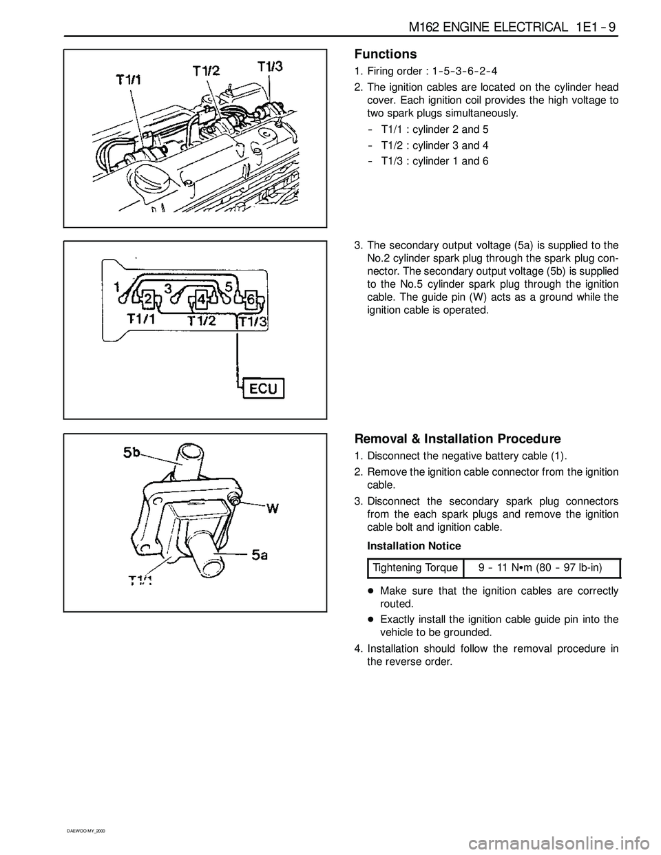
Functions
1. Firing order : 1 -- 5 -- 3 -- 6 -- 2 -- 4
2. The ignition cables are located on the cylinder head
cover. Each ignition coil provides the high voltage to
two spark plugs simultaneously.
-- T1/1 : cylinder 2 and 5
-- T1/2 : cylinder 3 and 4
-- T1/3 : cylinder 1 and 6
3. The secondary output voltage (5a) is supplied to the
No.2 cylinder spark plug through the spark plug con-
nector. The secondary output voltage (5b) is supplied
to the No.5 cylinder spark plug through the ignition
cable. The guide pin (W) acts as a ground while the
ignition cable is operated.
Removal & Installation Procedure
1. Disconnect the negative battery cable (1).
2. Remove the ignition cable connector from the ignition
cable.
3. Disconnect the secondary spark plug connectors
from the each spark plugs and remove the ignition
cable bolt and ignition cable.
Installation Notice
Tightening Torque
9--11NSm (80 -- 97 lb-in)
DMake sure that the ignition cables are correctly
routed.
DExactly install the ignition cable guide pin into the
vehicle to be grounded.
4. Installation should follow the removal procedure in
the reverse order.