Page 17 of 37
VALUES AND SETTINGS
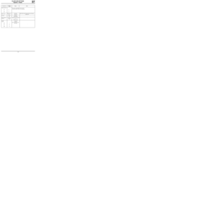
Dimensions
(1) Unladen
(2) Laden
07
12333R
Dimensions in metres
07-1
Page 18 of 37
VALUES AND SETTINGS
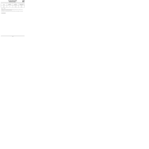
Capacity - Grades
07
Components
When
draining
3,5
3.7 (1)
2.7
2.9 (1)E.E.C. country
Other countries
Capacity
in litres
(approx.)*
Grade
Petrol engine
(oil)
D7F
E7J
0 °C+30 °C-30 °C
+10 °C+20 °C-20 °C-10 °C
-15 °C+25 °C
CCMC-G415W40-15W50
ACEA A2-96/A3-9615W40-15W50
CCMC-G510W30-10W40-10W50
ACEA A2-96/A3-96 10W30-10W40-10W50
CCMC-G55W30
ACEA A2-96/A3-965W30
CCMC-G55W40-5W50
ACEA A2-96/A3-965W40-5W50
API SH 10W40
API SH 10W30
0 °C+30 °C-30 °C+10 °C+20 °C-20 °C-10 °C
-15 °C
API SH 5W30
API SH 15W40
* Check with dipstick
(1) After replacing the oil filter
07-2
Page 19 of 37
VALUES AND SETTINGS
Capacity - Grades
07
When
draining
4.7
5.2 (1)E.E.C. country
Other countries
Diesel engine
(oil)
F8Q
0 °C+30 °C-30 °C
+10 °C+20 °C-20 °C-10 °C
-15 °C+25 °C
CCMC-PD215W40
ACEA B2-96/B3-9615W40
CCMC-PD210W40
ACEA B2-96/B3-9610W40
CCMC-PD25W30
ACEA B2-96/B3-965W30
CCMC-PD25W40
ACEA B2-96/B3-965W40
API CF 10W30
0 °C+30 °C-30 °C+10 °C+20 °C-20 °C-10 °C
-15 °C+15 °C
API CF 15W40
API CF 10W40
* Check with dipstick
(1) After replacing the oil filter
Components
Capacity
in litres
(approx.)*
Grade
07-3
Page 20 of 37
VALUES AND SETTINGS
Capacity - Grades
07
3.4
Manual gearbox
ComponentsCapacity
in litresGradeNotes
JB13.4
Brake circuitBrake fluids must be approved by the Technical
DepartmentSAE J 1703
and DOT 4
All countries: TRANSELF TRX 75 W 80 W
( API GL5 or MIL-L 2105 C or D standards)
Normal : 0.7
ABS : 1
Fuel tankapprox.
50 Unleaded
petrol/diesel
JB3
Separate
reservoir
1.1
Cooling
circuit
D7F
E7J
F8Q
-
GLACÉOL RX
(type D)
Only add coolant of the
same type
5
5.5
7.4
Power assisted
steering
-
ELF RENAULT MATIC D2
or
MOBIL ATF 220
-
07-4
Page 21 of 37

VALUES AND SETTINGS
Belt tension
07
96601R
SPECIAL TOOLING REQUIRED
Mot. 1273 Tool for checking belt tension
A Sensor
B Display
C Connecting cable
D Calibration checking plate
Principle
The sensor, through the presser button (1), the
presser (2) and the outer pads (3), applies a
constant force to the belt.
The reaction from the belt is measured using a
test piece (4) fitted with strain gauges.
Any movement on the gauges creates a variation
in their electrical resistance. This variation, once it
has been converted by the device, is displayed on
the display in SEEM units (US).Calibrating the device
The device is set in the factory; however it must be
recalibrated every six months.
Procedure
Resetting the zero:
- switch on the device (button E) with the presser
button (1) face down,
- if 0 is displayed, do not touch anything,
- if nothing is displayed, check the condition of
the 9 volt battery in the device ,
- if a value other than 0 is displayed, adjust screw
(F) until 0 is obtained.
07-5
Page 22 of 37
.
Position the calibration spring plate (Z) on the sensor as shown on the diagram (control value engraved t")
VALUES AND SETTINGS
Belt tension
07
Checking the calibration
Switch on the device (button E).
Position the calibration spring plate (Z) on the sensor as shown on the diagram (control value engraved to-
wards the top, (A) minimum value, (B) maximum value).
Tighten the presser button (1) until it goes "CLICK - CLICK - CLICK".
Check that a value X between the values (A and B) (A ≤ X ≤ B) is displayed.
NOTE: it may be necessary to perform several preliminary tests in order to obtain the correct value.
If the correct value if still not obtained after several attempts, contact SEEM.
NOTE : each device has its own calibration spring plate and they are not interchangeable.
96602R
1 Knurled button (presser)
A
B
Z Calibration plate
Calibration plate control value
SEEM
Contact your After Sales Head Office for further
information.
GENERAL INSTRUCTIONS:
_ Never refit a belt which has been removed, re-
place it.
- Never retighten a belt for which the tension
reading is between the fitting value and the
minimum operating value.
- When checking, if the tension is below the mi-
nimum operating value, change the belt.
07-6
Page 23 of 37
VALUES AND SETTINGS
Accessories belt tension
07
RIBBED BELT
Tensioning process
Engine cold (ambient temperature).
Fit the new belt.
Position the sensor of Mot. 1273.
Turn the wheel of the sensor until it disengages (three "CLICKS").
Tension the belt until the recommended fitting value is displayed on Mot. 1273 .
Lock the tensioner, check it, adjust the value.
Turn the crankshaft over three times.
Check that the tension value is within the fitting tension tolerance, otherwise readjust it.
NOTE :
Never refit a belt which has been removed.
Replace the belt if the tension is below the minimum operating tension.
Small cuts or cracks do not mean that the belt has to be replaced.
07-7
Page 24 of 37
VALUES AND SETTINGS
Accessories belt tension
07
10071R2
A Crankshaft
B Alternator
C Power assisted steering pump
T Tensioner
→Point for checking belt tension
ALTERNATOR BELT
D7F
ENGINE
Tension
(US=SEEM unit)Alternator
belt,
multitoothPower assisted
steering belt,
multitooth
Fitting102 ± 7 96 ± 5
Minimum
operating53 43
POWER ASSISTED STEERING BELT
SPECIAL TOOLING REQUIRED
Mot. 1273 Tool for checking the belt tension
97267R4
07-8


 Unladen
(2) Laden
07
12333R
Dimensions in metres
07-1")

2.7
2.9 (1)E.E.C. country
Other countries
Capacity
in litres
(approx.)*
Grade
Petrol engine
(oil)
D7F
E7J
0 °C+30 °C-30")
E.E.C. country
Other countries
Diesel engine
(oil)
F8Q
0 °C+30 °C-30 °C
+10 °C+20 °C-20 °C-10 °C
-15 °C+25 °C
CCMC-PD215W40")

.
Fit the new belt.
Position the sensor of Mot. 1273.
Turn the wheel of the sensor until")
