Page 1 of 37
77 11 194 217JULY 1997Edition anglaise
General
SPECIFICATIONS
LIFTING
TOWING
LUBRICANTS CONSUMABLES
DRAINING FILLING
FC0A - FC0C - FC0D - FC0E - KC0A - KC0C - KC0D - KC0E
VALUES AND SETTINGS
Renault 1997
"The repair methods given by the manufacturer in this document are based on the
technical specifications current when it was prepared.
The methods may be modified as a result of changes introduced by the
manufacturer in the production of the various component units and accessories
from which his vehicles are constructed."All copyrights reserved by Renault.
Copying or translating, in part or in full, of this document or use of the service part
reference numbering system is forbidden without the prior written authority of
Renault.
C
Page 2 of 37
Page 3 of 37
TOWING
All types
Contents
SPECIFICATIONS
Engine - Clutch - Gearbox
Vehicle identification
01-1
01-2
LIFTING
Trolley jack - Axle stands
Underbody lifts
Page
01
02
03
General
vehicle
02-1
02-2
03-1
LUBRICANTS CONSUMABLES
Packaging
04-1
DRAINING FILLING
Engine
Gearbox
Power assisted steering
04
05
05-1
05-3
05-4
VALUES AND SETTINGS
Dimensions
Capacity - Grades
Belt tension
Accessories belt tension
Timing belt tension
Tightening the cylinder head
Tyres and wheels
Brakes
Brake limiter
Underbody heights
Values for checking the front axle
geometry
Values for checking the rear axle
geometry07
07-1
07-2
07-5
07-7
07-11
07-12
07-14
07-15
07-16
07-17
07-20
07-21
Page
Page 4 of 37

The KANGOO Workshop Repair Manual has been prepared by specialists in repair methods
and diagnostics.
The document covers the methods and the diagnostic operations needed in order to obtain
high quality repairs for this vehicle.
However, if a removal - refitting operation involves no particular features, difficulties or
special tools, the method is not described in this manual, being considered very simple for
a vehicle repair specialist.
The labour times are the result of time and motion studies carried out in our workshops,
even though certain methods have not been described in the Workshop Repair Manual.
UNITS OF MEASUREMENT
• All dimensions are expressed in millimetres (mm) unless otherwise indicated.
• Tightening torques are expressed in decaNewton.metres (
daN.m).
• Pressure are given in
bars (reminder: 1 bar = 100 000 Pa).
• Electrical resistance values are in Ohms (Ω).
• Voltages are expressed in Volts (
V).
TOLERANCES
Tightening torques given without a tolerance must be accurate to within:
• In
degrees : ± 3°.
• In
daN.m : ± 10 %.
Page 5 of 37
SPECIFICATIONS
Engine- Clutch - Gearbox
01
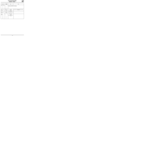
Vehicle typeEngine
TypeCapacity
(cm
3)Clutch type Manual gearbox type
FC0A
KC0AD7F 1149 180 CP 3300 JB1
FC0C
KC0CE7J 1390 180 CP 3300 JB3
FC0D
KC0D
FC0E
KC0EF8Q 1870 200 CPOV 3250 JB1
VEHICLE IDENTIFICATION
Example : FC0A
F : Body type
C : Project code
0A : Engine suffix
01-1
Page 6 of 37
SPECIFICATIONS
Vehicle identification
01
LOCATION OF VEHICLE IDENTIFICATION PLATE
e0-00/00-0000-000-000-00
VF000000000000000
0000 kg
0000 kg
1
- 0000 kg
2
- 0000 kg
000000000000000
RENAULT S.A.
1
2
3
4
5
8 7
6
9
10
13
12 11
1 Type mines of the vehicle and chassis number
2 PTMA [total all up weight of the vehicle]
3 PTR [maximum permitted total train weight -
vehicle loaded with trailer]
4 Maximum permitted weight on the front axle
(P.T.M.A. front axle)
5 Maximum permitted weight on the rear axle
(P.T.M.A. rear axle)6 Technical specifications of the vehicle
7 Paint reference
8 Equipment level
9 Vehicle type
10 Trim code
11 Additional factory optional equipment
12 Fabrication number
13 Interior matching trim code
13187R
01-2
Page 7 of 37

LIFTING
Trolley jack - Axle stands
AXLE STANDS
When putting the vehicle on axle stands, they
must be positioned:
_ either under the reinforcements provided for
lifting the vehicle with the tool kit jack,
- or under the studs located behind the
reinforcements.
Positioning of axle stands at the rear is carried out
by lifting the vehicle at the sides.
02
Safety symbol (special precautions to be taken when carrying out operations).
SPECIAL TOOLING REQUIRED
Cha. 280 -02 Adaptable cross piece for trolley jack
Cha. 408 -01
or Adaptable socket for trolley jack
Cha. 408 -02
If a trolley jack is used, appropriate axle
stands must always be used.
It is forbidden to lift the vehicle by supporting its
weight under the front suspension arms or under
the "V" member of the rear axle.
Depending on the type of trolley jack, use sockets
Cha. 408-01 or Cha. 408-02 for positioning the
cross piece Cha. 280-02.
To lift at the front or the rear of the vehicle, take
the weight under the side jacking points.
TROLLEY JACK AT THE SIDE
Use cross piece Cha. 280-02.
Take the weight under the valance at the level of
the front door.
Position the flange correctly in the groove of the
cross piece.
12333-2G
12274-1R
85679-1G15
02-1
Page 8 of 37
LIFTING
Underbody lifts
02
SAFETY INSTRUCTIONS
Various cases have to be considered:
1-
REMOVING COMPONENTS
As a general rule, never use a 2 post lift whenever
a four post lift can be used.
If this is not possible, place the lifting pads
beneath the underbody flange at the level of the
tool kit jack supports.
98703S
FRONT
98704S
REAR
These must be positioned level with the tool kit
jack supports. They must slot into the openings in
the underbody flanges.
2-
REMOVING - REFITTING THE ENGINE AND
TRANSMISSION ASSEMBLY
In this particular case, the vehicle body must be
secured to the arms of the 2 post lift using special
pads.
Company FOG
Part Number FOG 449 8111 - 449 8411
or
Company CHEMICO
Part Number 39 2550 0001
or
Company SCHENCH
Part Number 776 684
02-2


Clutch type Manual gearbox type
FC0A
KC0AD7F 1149 180 CP 3300 JB1
FC0C
KC0CE7J 1390 180 CP 3300 JB3
FC0D
KC0D
FC0E
KC0E")

