Page 188 of 208

EXHAUST
General
19
FITTING THE AFTER SALES SLEEVE
95478R1
Once a collar has been used once, renew it.
The nut on the collar has a groove (A) to ensure it
is tightened to the correct torque. When the nut is
tightened and the groove disappears, it causes a
distinct clicking sound and the nut is then tighte-
ned to the correct torque (2.5 daN.m).
NOTE : there are two different diameters of
sleeve available:
-∅ 50 mm,
-∅ 45 mm .
IMPORTANT:
- check that there is no point of contact bet-
ween the exhaust pipe and the vehicle body,
- check for the presence and correct positioning
of all heat shields for the exhaust pipe,
- check that the two cutting marks are correctly
aligned.
99227S
To avoid any leaks in the exhaust pipe, the sleeve
must be correctly positioned over the two exhaust
pipe sections. The pipe must be against the stops
inside the sleeve.
Begin by positioning the sleeve over the used sec-
tion of the pipe, adjust the collar by tightening
gently.
Check the position of the pipe in relation to the
stops.
Fit the new section of the pipe.
Before fitting the sleeve on the pipe, apply a little
mastic to the inner ring on the sleeve to prevent
leaks.
(Exhaust mastic, Part Number. 77 01 421 161
SODICAM).
IMPORTANT : the bolt and nut used for tighte-
ning the sleeve must be aligned vertically to
avoid any risks of touching the underside of the
body.
19-14
Page 191 of 208
Mot. 1199-01 Exhaust pipe cutting tool
Mot. 1265
Mot. 1265-01
FUEL TANK
Fuel tank
19
IMPORTANT : during all the fuel tank removal
and refitting operations, refrain from smoking
and be sure not to handle incandescent objects in
the vicinity of the working area.
DRAINING THE FUEL TANK (Petrol version)
Remove the pump-sender unit assembly steel ac-
cess cover.
Remove the clip which shows if the assembly has
been pushed in (if fitted).
Disconnect the quick release union at (1), tool
Mot. 1265.
EQUIPMENT REQUIRED
INTAIRCO pneumatic siphoning pump, for
petrol or diesel tank draining system (see EQUIPMENT
catalogue).
SPECIAL TOOLING REQUIRED
97163R2
Attach to the outlet at (A), a pipe long enough to
be placed into a container outside the vehicle .
NOTE : Alternatively, an INTAIRCO pneumatic si-
phoning pump may be used (see
EQUIPMENT ca-
talogue). Sender unit- pump nut 7
TIGHTENING TORQUES (in daN.m)
Pliers for removing quick release
fuel unions
19-17
Page 204 of 208

Mot. 1264 Wrench for removing
Mot. 1264-01 pump-sender unit assembly nut
Mot. 1265 Pliers for removing
Mot. 1265-01 quick release unions
FUEL TANK
Pump- sender unit
19
SPECIAL TOOLING REQUIRED
IMPORTANT :
During all operations on the fuel tank or on the
fuel supply circuit , it is vital :
- to refrain from smoking and handling incan-
descent objects in the vicinity of the working
area,
- to avoid fuel projections, due to the residual
pressure present in the pipes during removal .
REMOVAL
To remove the pump-sender unit assembly, it is
not necessary to remove the tank, as it is accessi-
ble through the inside of the vehicle. To do this :
- disconnect the battery,
- lift the rear bench seat ,
- remove the steel access cover,
- remove the electrical connection at (1),
- remove the clips at (2).
97163R5
Nut for pump - sender unit assembly 7
TIGHTENING TORQUES (in daN.m)Disconnect, using tool Mot. 1265 or Mot. 1265-
01:
- the fuel supply pipe (3) (which is marked by a
green quick release union),
- the fuel return pipe (4) (marked by a red quick
release union and by an arrow (B)).
96420R1
19-30
Page 205 of 208

FUEL TANK
Pump- sender unit
19
REFITTING
Check that the seal is not deformed, and replace it
if necessary.
Position the pump-sender unit assembly
(ensuring that the arrow at (F) is placed in the
longitudinal axis of the vehicle pointing to the
rear).
Position the nut and tighten it to the torque of
3.5 daN.m.
Fit the fuel pipes (it is not necessary to use the
pliers Mot. 1265 or Mot. 1265-01).
Refit the safety clips at (2).
Reconnect the electrical connection.
Refit the steel cover.
ALLOCATION OF CONNECTOR TRACKS
TRACK ALLOCATION
A1 Earth
A2 Fuel minimum level warning light
B1 Sender unit information to instrument
panel
B2 Not used
C1 pump
C2 pump
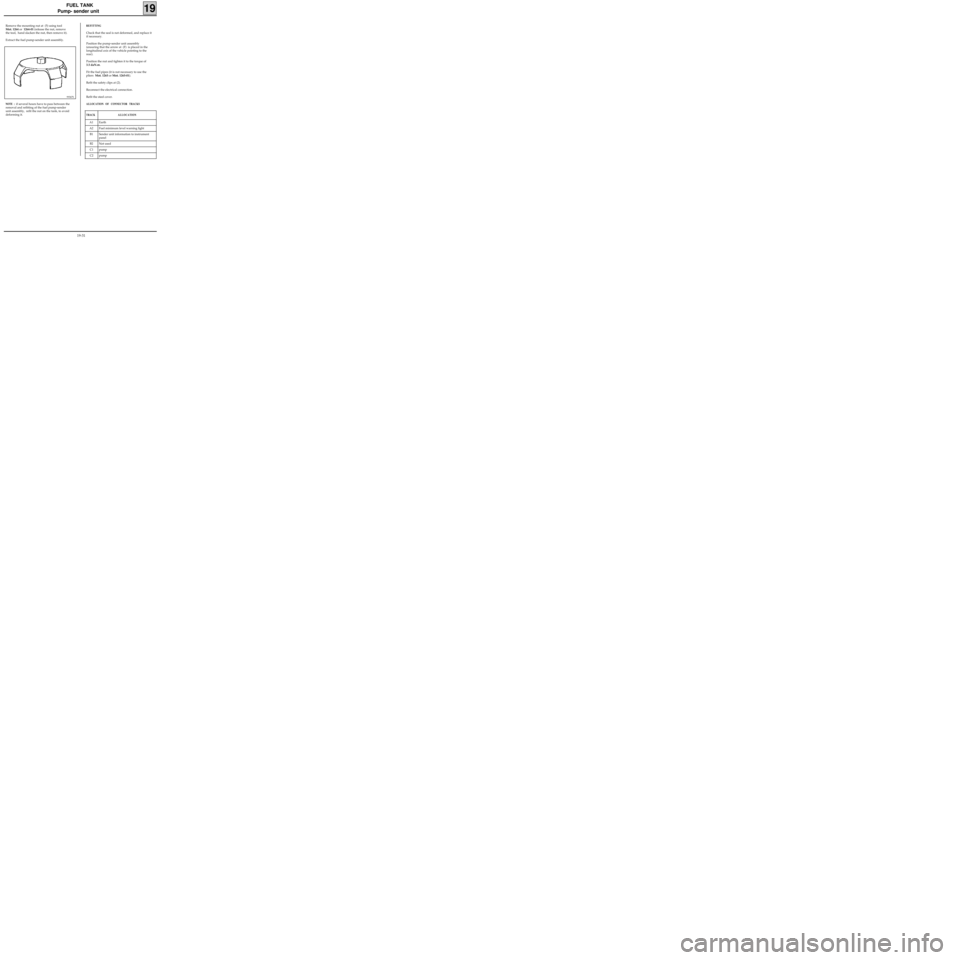
Remove the mounting nut at (5) using tool
Mot. 1264 or 1264-01 (release the nut, remove
the tool, hand slacken the nut, then remove it).
Extract the fuel pump-sender unit assembly.
99367S
NOTE : if several hours have to pass between the
removal and refitting of the fuel pump-sender
unit assembly, refit the nut on the tank, to avoid
deforming it.
19-31
Page 206 of 208
ENGINE MOUNTING
Suspended engine mountings
19
12924G
D7F Engine
TIGHTENING TORQUES (in daN.m)
13359S
19-32
Page 207 of 208
ENGINE MOUNTING
Suspended engine mountings
19
13359R3
D7F Engine
TIGHTENING TORQUES (in daN.m)
19-33
Page 208 of 208
ENGINE MOUNTING
Suspended engine mountings
19
13086R2
F8Q Engine
TIGHTENING TORQUES (in daN.m)
19-34