Page 104 of 208
DIESEL EQUIPMENT
Altimetric corrector
13
REFITTING
It is VITAL to remove the small filter (2) situated at
the bottom of the system using a pair of thin -
nosed pliers, and replace it with a new one.
Tighten the actuator (1) to a torque of 3 daN.m
using the socket Mot. 1440.
Place a new protective cover on the actuator.
Reconnect the two terminals to the connector.Reconnect the connector.
Replace the protective sheath on the wiring,
along with the retaining clip.
Bleed the diesel circuit using the priming pump
before starting the engine.
It is IMPERATIVE to erase the computer memory
by pressing G0**.
It is vital to road test the vehicle after this
operation.
13128R
F8Q 662
FUNCTION : it acts on the flow in proportion to altitude ; if the vehicle is running at
an altitude greater than or equal to 1 000 metres, the computer reduces the flow by
3 mm
3/stroke. The conventional flow is reestablished if the vehicle runs at an alti-
tude lower than 900 metres.
13-24
Page 107 of 208

DIESEL EQUIPMENT
Coded solenoid valve
13
On this type of vehicle, the replacement of the
solenoid valve and of the coded electronic unit (A)
requires the removal of the injection pump from
the engine.
REMOVAL
With the pump on the bench, remove the protec-
tive fittings at (B).
These are secured by shear bolts which may be re-
moved either :
- using a small cold chisel or a punch and hitting
on the conical heads of bolts (C), (D) and (E)
to loosen them,
- using tool Mot. 1372 for bolt (F), drilling it
using the 4 mm diameter drill (drilling depth
approximately 4 mm) and the large diameter
drilling guide tube on the fitting side (2).
Use extractor (3) and its handle to remove it .
REFITTING
Tighten the fuel cut off solenoid valve to a torque
of 2 daN.m.
Refit a heat shrink cover on the fuel cut off sole-
noid, ensuring the wiring is correctly routed.
Refit the fittings using shear bolts and observing
their location and that of the spacers,
(depending on fitting).
IMPORTANT : using a torque wrench, tighten the
bolts, then remove the bolt heads by bending
them using a tube inserted in the bolt heads.
Location of bolts :
D :
∅ 5 x 25 mm ; torque =0.55 daN.m
C and F :
∅ 6 x 40 mm ; torque =1.2 daN.m
E :
∅ 5 x 33 mm ; torque =0.55 daN.m
Refit the cable of the fast idle speed LDA and
tighten the cable grip, leaving 2 mm play.
Refit the injection pump on the engine.
13-27
Page 111 of 208
DIESEL EQUIPMENT
Injector with sensor (needle lift)
13
10579R1
PRM1315
The needle lift sensor is integrated to the injector
holder (cylinder n° 3). Its function is to transmit
the movements of the injector needle to the
computer. This allows the start of injection to be
deduced. The computer processes this informa-
tion and uses it to compare the advance reques-
ted to the advance corrector on the pump to the
advance actually applied . In this way, the system
works as a closed loop.
Tooling required for the removal of the injector :
Mot. 997-01.
Tightening torque: 7 daN.m.
NOTE : it is possible to modify tool Mot. 997 by
milling the socket at (A), through which passes
the connector of the injector with sensor (B).1 Plunger rod
2 Spacer
3 Injector
4 Spring
5 Winding
13-31
Page 119 of 208
DIESEL EQUIPMENT
Pump
13
REMOVAL
Disconnect the battery. Then remove :
- the suspended engine mounting housing (1),
- the injection pump pulley housing (2).
DI1302-1
Pin the engine using tool Mot. 1054. For this
operation, turn the engine so that the index of
the camshaft sprocket is in line with the marking
on the timing cover (use a mirror).
SPECIAL TOOLING REQUIRED
Mot. 1054TDC pin
Mot. 1200
Pump-pulley retaining tool
Mot. 1317
99183R
Nut mounting the pump shaft
to the RAM pulley 4.5
Pump mounting bolt 2.2
TIGHTENING TORQUES (in daN.m)
13-39
Page 120 of 208

DIESEL EQUIPMENT
Pump
13
Remove :
- the fuel supply pipe (A),
- the fuel return pipe (B),
- the pump connector (C),
- the accelerator cable (D),
- the vacuum pipe (E) connected to the fast
idle speed LDA,
- the high pressure wiring loom using tool Mot.
1383,
10578R
- the rear support mounting bolt.
12869R
Fit tool Mot. 1200 or Mot. 1317 , for retaining the
pump pulley.
12410R
Inserting a torx screwdriver in the gaps of the
RAM pulley, slacken:
- the three bolts mounting the pump
- the central nut securing the pump shaft to the
RAM pulley.
Slacken the central nut and all three of the bolts
mounting the pump until they are completely
free.
Extract the pump.
REFITTING
Clean the pump shaft very thoroughly, using sol-
vent to eliminate all trace of grease.
Refit the pump.
Tighten the three bolts mounting the pump .
Pretighten the central nut of the pump to 2
daN.m.
IMPORTANT : it is vital to carry out a pretighte-
ning operation before the final tightening; tigh-
ten the central pump nut to a torque of 4.5
daN.m.
Carry out the timing operations (see "Pump -
Timing").
For all other operations, refitting is the reverse of
removal.
13-40
Page 121 of 208

DIESEL EQUIPMENT
Pump - Timing
13
IMPORTANT : the engine must only be rotated by
turning a wheel, in 5th gear, and in its operating
direction; if it is accidentally turned in the
opposite direction, repeat the operations for
checking and adjusting the timing.
CHECKING THE SETTING OF INJECTION PUMPS
FITTED WITH RAM PULLEYS
Turn the engine twice in the operating direction
(moving one wheel and having engaged 5th
gear).
Remove the timing shaft plug situated on the
pump cover.
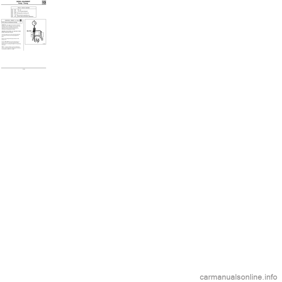
Fit tool Mot. 1079 and zero the dial gauge on
pump cam "rest" zone (this operation will be
made easier by turning the engine in its operating
direction).
NOTE : in order to obtain a precise adjustment,
and to avoid bringing the dial gauge to its limit, it
is advisable to adjust it to 1 mm.
SPECIAL TOOLING REQUIRED
Mot. 1054TDC pin
Mot. 1079 LUCAS pump timing kit
Mot. 1200
Mot. 1317
Mot. 135 Set of tools for operations on a
Mot. 1359 RAM pulley (micrometric adjustment)
91258R2
RAM pulley nut (adjustment locking) 9
TIGHTENING TORQUES (in daN.m)
Pump-pulley retaining tool
13-41
Page 125 of 208

DIESEL EQUIPMENT
Pump - Timing
13
DI1303-1
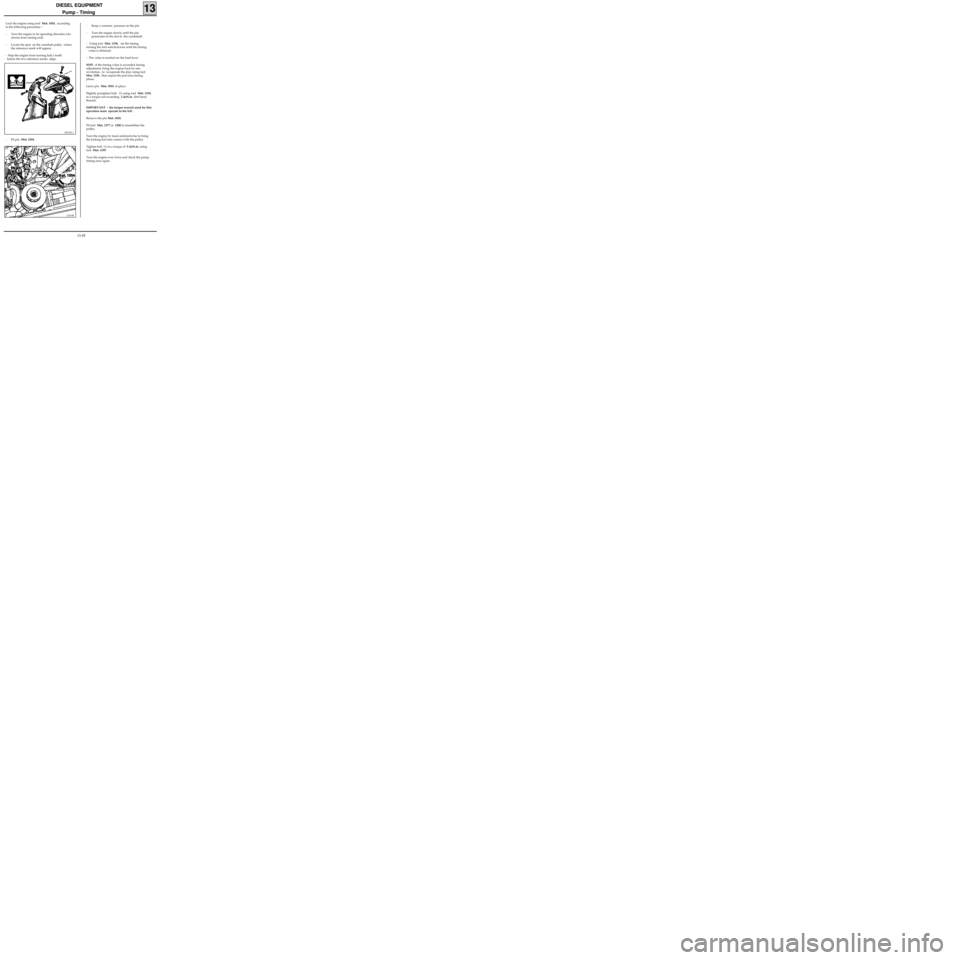
- Fit pin Mot. 1054.
12419R
- Keep a constant pressure on the pin.
- Turn the engine slowly until the pin
penetrates in the slot in the crankshaft.
- Using tool Mot. 1358, set the timing,
turning the tool anticlockwise until the timing
value is obtained.
- The value is marked on the load lever.
NOTE : if the timing value is exceeded during
adjustment, bring the engine back by one
revolution , to recuperate the play using tool
Mot. 1358 , then repeat the previous timing
phase.
Leave pin Mot. 1054 in place.
Slightly pretighten bolt (1) using tool Mot. 1359,
to a torque not exceeding 2 daN.m (left hand
thread).
IMPORTANT : the torque wrench used for this
operation must operate to the left .
Remove the pin Mot. 1054.
Fit tool Mot. 1377 or 1200 to immobilise the
pulley.
Turn the engine by hand anticlockwise to bring
the locking tool into contact with the pulley.
Tighten bolt (1) to a torque of 9 daN.m, using
tool Mot. 1359.
Turn the engine over twice and check the pump
timing once again.
Lock the engine using tool Mot. 1054, according
to the following procedure :
- Turn the engine in its operating direction (clo-
ckwise from timing end).
- Locate the spot on the camshaft pulley where
the reference mark will appear .
- Stop the engine from turning half a tooth
before the two reference marks align.
13-45
Page 153 of 208
IGNITION
Spark plugs
17
Engine Make Type
D7F
EYQUEM
NGK
RFC 50 LZ 2E
BKR 5EK
E7JEYQUEM
CHAMPIONRFC 52 LS
RC 10 PYC
Flat skirt with seal
Gap: 0.9 mm
Tightening torque : 2.5 to 3 daN.m
D7F Engine
To disconnect the spark plug leads, use the tool (3), which is integrated to the plastic cover (4) on the cylin-
der head.
99940R
99894R1
D7F/E7J
Engines
NOTE : to remove the spark plugs, use the tool kit, Ele. 1382.
17-3