Page 165 of 208
INJECTION
Immobiliser function
17
This vehicle is fitted with a 2nd generation immobiliser system.
REPLACING THE INJECTION COMPUTER
All computers are supplied uncoded, but are capable of being programmed with a code.
When replacing the computer, the vehicle code must be programmed in and then a check must be made to
ensure that the immobiliser system is operational.
To do this, it is sufficient to carry out the following operations:
- turn the ignition on for a few seconds and turn it off again,
- remove the key to guarantee the immobiliser function.
CHECKING THE IMMOBILISER FUNCTION
Remove the key from the ignition switch. After 10 seconds the red immobiliser warning light will flash.
For special notes on testing an injection computer (test part), refer to section 82: "Immobiliser".
17-15
Page 171 of 208
INJECTION
Richness regulation
17
Non-loop mode
When richness regulation is occurring, the operating phases when the computer ignores the voltage informa-
tion from the oxygen sensor are:
- Full load: #35 = variable and greater than 128
- Sharp acceleration: #35 = variable and greater than 128
- Deceleration with no load information (injection cut) : #35 = 128
- Oxygen sensor fault: #35 = 128
DEFECT MODE IN THE EVENT OF AN OXYGEN SENSOR FAULT
If the voltage from the oxygen sensor is incorrect (# 05 varies only slightly or not at all) during richness regu-
lation, the computer will only enter defect mode (# 35 = 128) if the fault has been present for 3 to 5 minutes.
The fault will be memorised in this case only.
If an oxygen sensor fault is present and recognised and if the fault has already been stored, the system enters
the open loop mode directly (# 35 = 128)
17-21
Page 194 of 208
FUEL TANK
Fuel tank
19
Before the handbrake adjuster is disengaged, di-
mension X must be noted.
Disengage the adjuster in such a way that both
the left and right hand cables can be easily relea-
sed (carefully release the plastic cable stop (6)).
Disconnect the two unions at (7) and (8) using
tool Mot. 1265.
Disconnect the pipe at (9).
Separate the tank from the filler neck (10).
Unclip the handbrake cables from under the tank
(11).Unclip the hydraulic brake pipes on the fuel tank
side.
Unclip the fuel pipes from the tank.
Position a component jack under the fuel tank.
Remove the four bolts mounting the tank.
Tilt the tank slightly forwards, then remove it.
REFITTING
Refitting is the reverse of removal.
Take care not to pinch any pipes (risk of leaks).
Fit the quick release unions by hand and ensure
they connect correctly.
Take care to ensure the heat shields are correctly
refitted.
12873R
99091R1
19-20
Page 205 of 208

FUEL TANK
Pump- sender unit
19
REFITTING
Check that the seal is not deformed, and replace it
if necessary.
Position the pump-sender unit assembly
(ensuring that the arrow at (F) is placed in the
longitudinal axis of the vehicle pointing to the
rear).
Position the nut and tighten it to the torque of
3.5 daN.m.
Fit the fuel pipes (it is not necessary to use the
pliers Mot. 1265 or Mot. 1265-01).
Refit the safety clips at (2).
Reconnect the electrical connection.
Refit the steel cover.
ALLOCATION OF CONNECTOR TRACKS
TRACK ALLOCATION
A1 Earth
A2 Fuel minimum level warning light
B1 Sender unit information to instrument
panel
B2 Not used
C1 pump
C2 pump
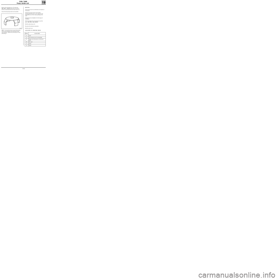
Remove the mounting nut at (5) using tool
Mot. 1264 or 1264-01 (release the nut, remove
the tool, hand slacken the nut, then remove it).
Extract the fuel pump-sender unit assembly.
99367S
NOTE : if several hours have to pass between the
removal and refitting of the fuel pump-sender
unit assembly, refit the nut on the tank, to avoid
deforming it.
19-31
Page:
< prev 1-8 9-16 17-24