Page 62 of 208
TOP AND FRONT OF ENGINE
Cylinder head gasket
11
Wear gloves whilst carrying out this operation.
99180S
CHECKING THE GASKET FACE
Check for gasket face bow, using a straight edge
and a set of shims.
Maximum deformation: 0.05 mm.
No regrinding of the cylinder head is permitted.
Check the cylinder head for cracks.
F8Q Engine
CLEANING
It is very important not to scratch the gasket faces
of the aluminium components.
Use the Décapjoint product to dissolve any part of
the gasket which remains attached.
Apply the product to the parts to be cleaned; wait
about ten minutes, then remove it using a
wooden spatula.
11-27
Page 63 of 208

TOP AND FRONT OF ENGINE
Cylinder head gasket
11
REFITTING (special notes)
Refit the cylinder head gasket selected previous-
ly. This is centred by two dowels at (C).
99173-1R
Bring the pistons to mid-stroke position to
prevent them from coming into contact with the
valves during the tightening of the cylinder head .
Centre the cylinder head on the dowels.
Lubricate the threads and under the heads of the
mounting bolts.
Tighten the cylinder head (see section 07
"Tightening the cylinder head").
Refitting is the reverse of removal.
Refit the timing belt, (see method described in
section 11 "Timing belt").
Fill and bleed the cooling circuit , (see section 9
"Filling -bleeding").
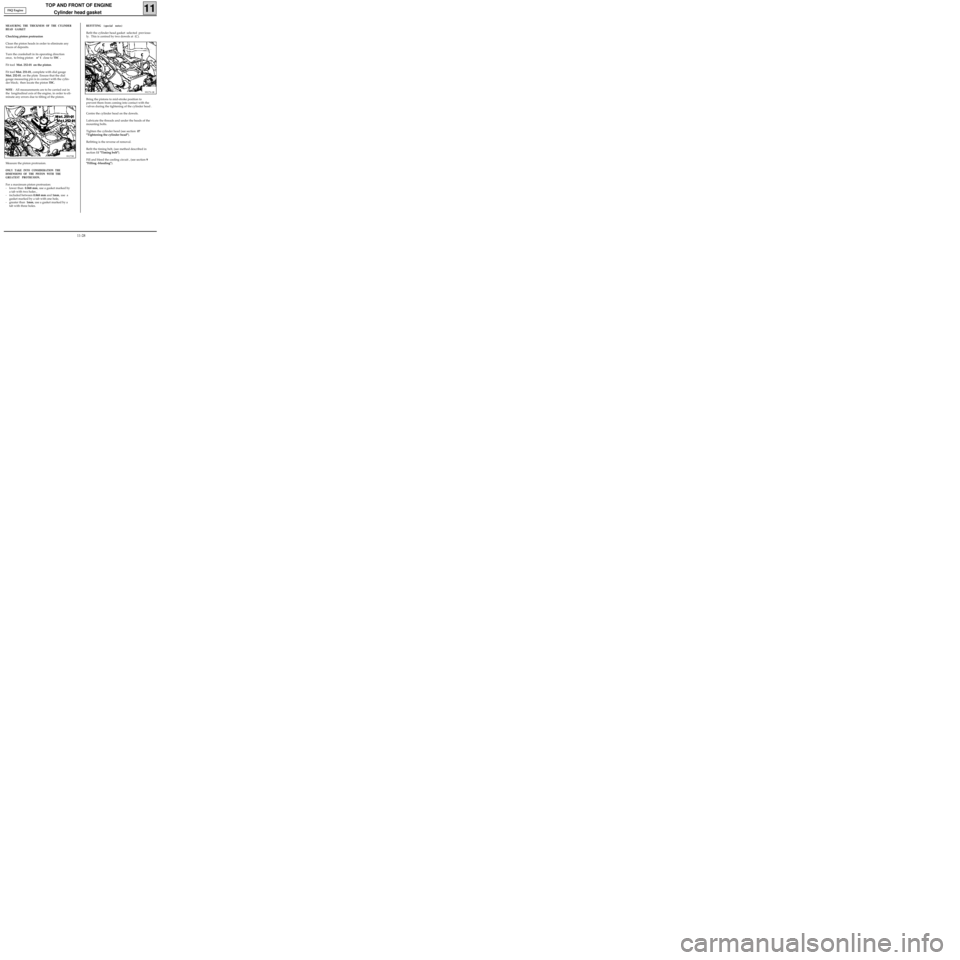
MEASURING THE THICKNESS OF THE CYLINDER
HEAD GASKET
Checking piston protrusion
Clean the piston heads in order to eliminate any
traces of deposits.
Turn the crankshaft in its operating direction
once, to bring piston n° 1 close to
TDC .
Fit tool Mot. 252-01 on the piston.
Fit tool Mot. 251-01, complete with dial gauge
Mot. 252-01. on the plate Ensure that the dial
gauge measuring pin is in contact with the cylin-
der block; then locate the piston
TDC.
NOTE
: All measurements are to be carried out in
the longitudinal axis of the engine, in order to eli-
minate any errors due to tilting of the piston.
99173R
Measure the piston protrusion.
ONLY TAKE INTO CONSIDERATION THE
DIMENSIONS OF THE PISTON WITH THE
GREATEST PROTRUSION.
For a maximum piston protrusion:
- lower than 0.868 mm, use a gasket marked by
a tab with two holes ,
- included between 0.868 mm and 1mm, use a
gasket marked by a tab with one hole,
- greater than 1mm, use a gasket marked by a
tab with three holes. F8Q Engine
11-28
Page 64 of 208
TOP AND FRONT OF ENGINE
Replacement of valve adjusters
11
SPECIAL TOOLING REQUIRED
Mot. 1366-01 Tool for removing valve adjusters
(additional item to Mot. 1366)
TIGHTENING TORQUES (in daN.m)
Studs for mounting manifolds on
cylinder head 1
Nut for mounting manifolds on
cylinder head 2.7
Mounting bolt for strut on inlet manifold 2.5
Mounting bolt for strut on cylinder block 2.5
Place the vehicle on a two-post lift
Disconnect the battery.
CHECKING THE VALVE CLEARANCE
Remove the air filter housing along with the cy-
linder head cover.
Place the valves of the cylinder concerned at the
"end of exhaust - beginning of inlet" position and
check the clearance .
86911-1S
1
3
4
24
2
1
3
Compare the two dimensions noted to the re-
commended dimensions, and replace the adjus-
ters if necessary .
Clearance ( in mm ), when the engine is cold :
- Inlet: 0.10
- Exhaust :0.25 F8Q Engine
11-29
Page 87 of 208

FUEL SUPPLY
Pump flow
13
Petrol
engines
96093R2
SPECIAL TOOLING REQUIRED
Mot. 1265 Pliers for removing quick release
unions
EQUIPMENT REQUIRED
2 000 ml measuring cylinder
It is advised to check the pump supply flow
through the fuel return pipe connected to the
pump-fuel sender unit assembly.
IMPORTANT
During this operation, it is essential :
• to refrain from smoking and handling incan-
descent objects close to the working area,
• to take precautions against possible fuel
projections which may occur due to the resi-
dual pressure in the supply pipes when they
are removed.
CHECKING THE PUMP FLOW
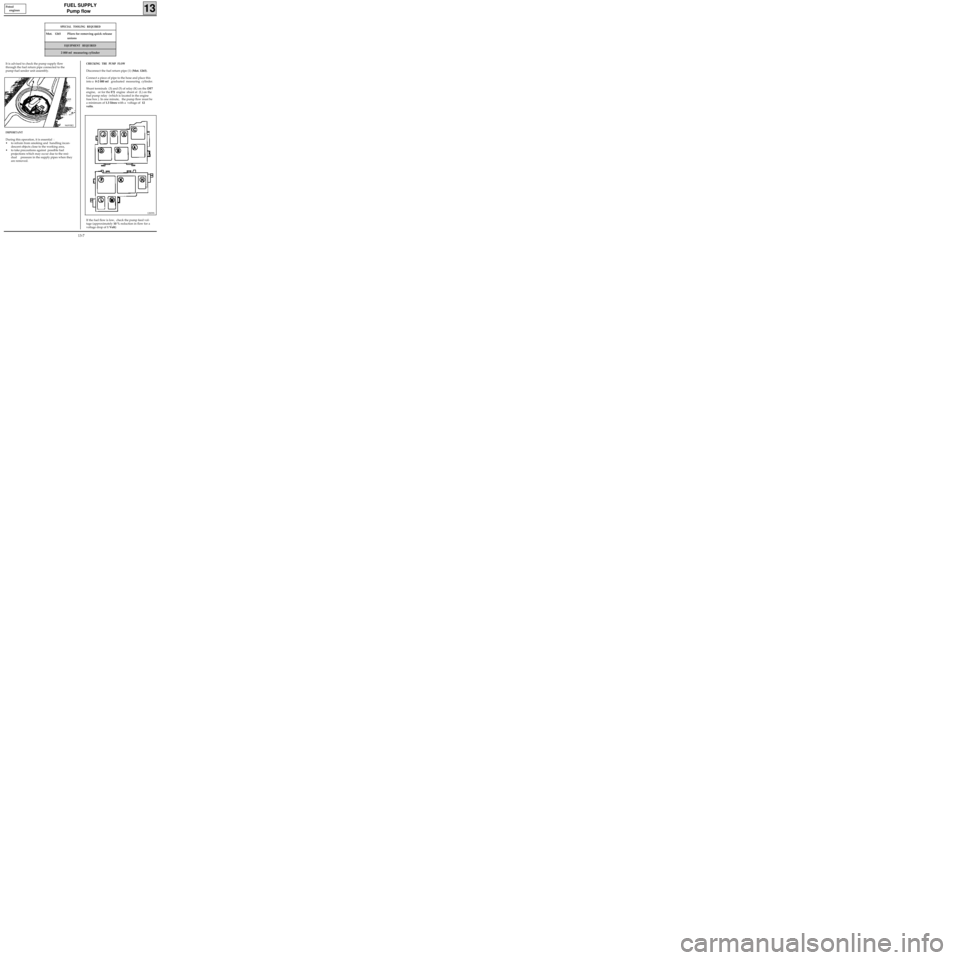
Disconnect the fuel return pipe (1) (Mot. 1265).
Connect a piece of pipe to the hose and place this
into a 0-2 000 ml graduated measuring cylinder.
Shunt terminals (3) and (5) of relay (K) on the DF7
engine, or for the
E7J engine shunt at (L) on the
fuel pump relay (which is located in the engine
fuse box ). In one minute, the pump flow must be
a minimum of 1.3 litres with a voltage of 12
volts.
If the fuel flow is low, check the pump feed vol-
tage (approximately 10 % reduction in flow for a
voltage drop of 1 Volt)
12839S
13-7
Page 88 of 208
FUEL SUPPLY
Fuel pressure
13
CHECKING THE FUEL PRESSURE
SPECIAL TOOLING REQUIRED
Mot. 1311-01 Fuel pressure test kit (with a pressure
gauge 0; + 10 bar tool kit)
Mot. 1311-05 Junction tool (for union K)
Mot. 1311-06 Tool for removing fuel supply unions
IMPORTANT : during the opening of the fuel cir-
cuit , be sure to use a cloth to avoid possible pro-
jections of fuel due to the residual pressure.
Disconnect the fuel supply pipe using the tool
Mot. 1311-06 with the largest section (see method
described in section 13 "Injector gallery").
Connect tool Mot. 1311-05 to the injector gallery,
then reconnect the fuel supply pipe to the tool
itself.
99375R
99934R1
99939S
DF7 Engine
13-8
Page 90 of 208
FUEL SUPPLY
Fuel pressure
13
CHECKING THE FUEL PRESSURE
SPECIAL TOOLING REQUIRED
Mot. 1311-01 Fuel pressure test kit (with a pressure
gauge 0; + 10 bar tool kit)
Mot. 1311-05 Junction tool (for union J)
IMPORTANT : during the opening of the fuel cir-
cuit , be sure to use a cloth to avoid possible pro-
jections of fuel due to the residual pressure.
Disconnect the fuel supply pipe.
Fit tool Mot. 1311-04 on the injector gallery, then
reconnect the fuel supply pipe to the tool itself.
13244-1R
EF7 Engine
Connect the pressure gauge 0; + 10 bars with
the flexible pipe Mot. 1311-01.
99376R
13-10
Page 121 of 208

DIESEL EQUIPMENT
Pump - Timing
13
IMPORTANT : the engine must only be rotated by
turning a wheel, in 5th gear, and in its operating
direction; if it is accidentally turned in the
opposite direction, repeat the operations for
checking and adjusting the timing.
CHECKING THE SETTING OF INJECTION PUMPS
FITTED WITH RAM PULLEYS
Turn the engine twice in the operating direction
(moving one wheel and having engaged 5th
gear).
Remove the timing shaft plug situated on the
pump cover.
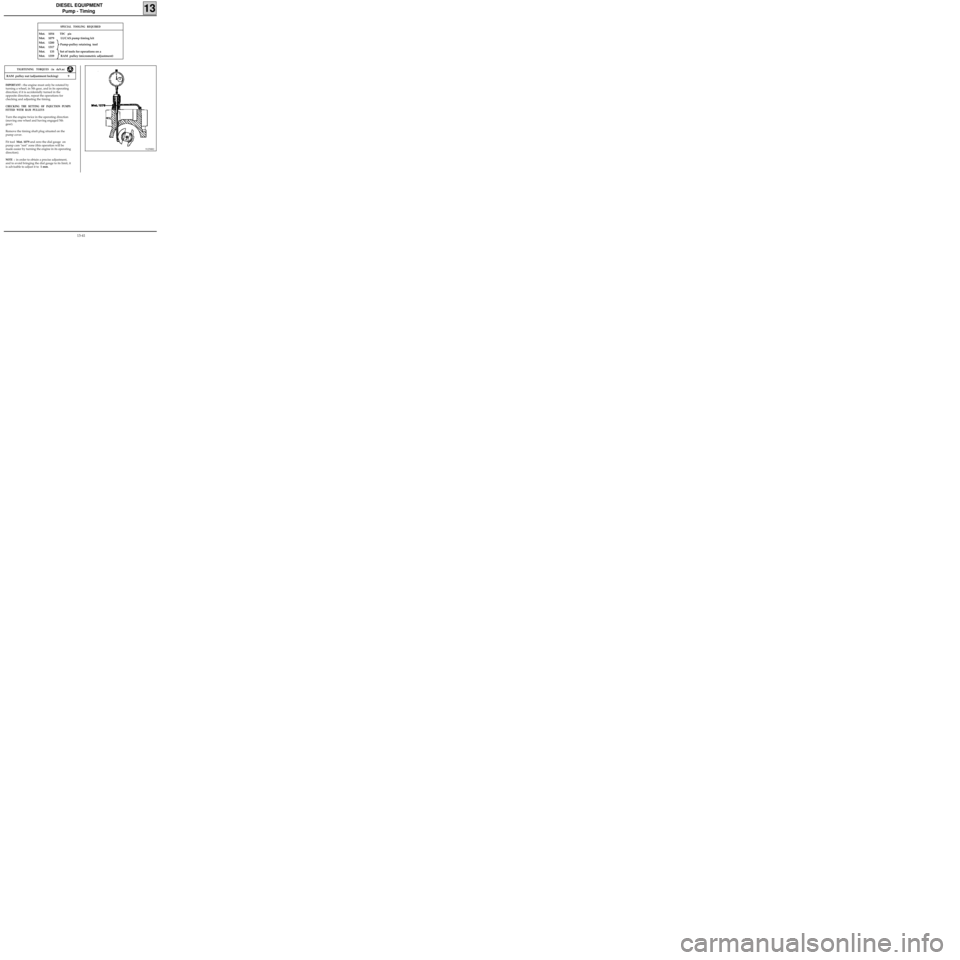
Fit tool Mot. 1079 and zero the dial gauge on
pump cam "rest" zone (this operation will be
made easier by turning the engine in its operating
direction).
NOTE : in order to obtain a precise adjustment,
and to avoid bringing the dial gauge to its limit, it
is advisable to adjust it to 1 mm.
SPECIAL TOOLING REQUIRED
Mot. 1054TDC pin
Mot. 1079 LUCAS pump timing kit
Mot. 1200
Mot. 1317
Mot. 135 Set of tools for operations on a
Mot. 1359 RAM pulley (micrometric adjustment)
91258R2
RAM pulley nut (adjustment locking) 9
TIGHTENING TORQUES (in daN.m)
Pump-pulley retaining tool
13-41
Page 122 of 208
DIESEL EQUIPMENT
Pump - Timing
13
Components of tool Mot. 1079
A Timing pin
B Dial gauge support
C30 mm dial gauge
91285R
Lock the engine using tool Mot. 1054, according
to the following procedure :
- Turn the engine in its operating direction (clo-
ckwise from timing end).
- Locate the spot on the camshaft pulley where
the reference mark will appear .
- Stop the engine from turning half a tooth be-
fore the two reference marks align.
DI1303-1
- Fit the pin, tool Mot. 1054.
12419R
- Keep a constant pressure on the pin.
- Turn the engine slowly until the pin
penetrates into the slot in the crankshaft .
- Check the pump piston lift, which may be read
on the dial gauge.
- The value is marked on the load
potentiometer lever.
- If the value is incorrect, adjust the timing (see
following method).
13-42