Page 125 of 208
DIESEL EQUIPMENT
Pump - Timing
13
DI1303-1
- Fit pin Mot. 1054.
12419R
- Keep a constant pressure on the pin.
- Turn the engine slowly until the pin
penetrates in the slot in the crankshaft.
- Using tool Mot. 1358, set the timing,
turning the tool anticlockwise until the timing
value is obtained.
- The value is marked on the load lever.
NOTE : if the timing value is exceeded during
adjustment, bring the engine back by one
revolution , to recuperate the play using tool
Mot. 1358 , then repeat the previous timing
phase.
Leave pin Mot. 1054 in place.
Slightly pretighten bolt (1) using tool Mot. 1359,
to a torque not exceeding 2 daN.m (left hand
thread).
IMPORTANT : the torque wrench used for this
operation must operate to the left .
Remove the pin Mot. 1054.
Fit tool Mot. 1377 or 1200 to immobilise the
pulley.
Turn the engine by hand anticlockwise to bring
the locking tool into contact with the pulley.
Tighten bolt (1) to a torque of 9 daN.m, using
tool Mot. 1359.
Turn the engine over twice and check the pump
timing once again.
Lock the engine using tool Mot. 1054, according
to the following procedure :
- Turn the engine in its operating direction (clo-
ckwise from timing end).
- Locate the spot on the camshaft pulley where
the reference mark will appear .
- Stop the engine from turning half a tooth
before the two reference marks align.
13-45
Page 126 of 208
DIESEL EQUIPMENT
Adjusting idle speed
13
12870R
It is vital to make these adjustments when the en-
gine is warm, and after the engine cooling fan
has operated at least twice.
The idle speed adjustment and anti-stalling
function adjustment must be carried out
correctly, since these operations directly
influence the behaviour of the engine at idle
speed and in the deceleration phase (hesitation
idle speed lasts too long, etc.).
1 Idle speed adjustment screw
2 Load lever
3 Residual flow adjustment screw (anti-stalling
function)
4 Fast idle lever
5 Idle speed cable grip
FAST IDLE SPEED
Without applying a vacuum to the LDA, position
the cable grip (5) at 2 ± 1 mm from the fast idle
speed lever (4).
NOTE : the fast idle speed value is not directly ad-
justable; it is adjusted on the injection unit.
CHECKING THE MAXIMUM SPEED
Whilst the engine is warm, accelerate to full load ;
the engine speed must be between 4 500 and
4 700 rpm (this adjustment can only be carried
out in a Renault Injection Centre workshop).
IDLE SPEED AND RESIDUAL FLOW ADJUSTMENT
(anti-stalling)
a)Ensure that the fast idle speed function is not
operational .
b)Adjust the idle speed to 825 ± 25 rpm. using
screw (1).
c)Place a 4 mm shim between the load lever (2)
and the residual flow screw (3).
d)Adjust the engine speed to 1 250 ± 50 rpm.
using the residual flow screw (3).
e)Remove the 4 mm shim then accelerate
sharply twice.
f)Check the conformity of the idle speed; if
necessary, repeat the idle speed adjustment
and check the residual flow once more.
13-46
Page 131 of 208
ANTIPOLLUTION
Fuel vapour rebreathing
14
CHECKING CANISTER BLEED OPERATION
Incorrect operation of the system may cause the
idle speed to be unstable or the engine to stall.
Check the conformity of the circuit (see
operational diagrams)
Be sure to check that the pipe marked "CAN" on
the solenoid valve is correctly connected to the
canister.
Check the condition of the pipes to the fuel tank.
97393R6
1Inlet manifold
2Canister bleed solenoid valve
3Canister
4Fuel tankAt idle speed connect a pressure gauge
(- 3 ; +3 bars) (Mot. 1311-01) to the "CAN" outlet
on the solenoid valve, to check there is no vacuum
(the command value read by the
XR25 for #23 re-
mains minimal X = 0.7 % ). Is there a vacuum ?
YESIgnition off, use a vacuum pump to apply a
vacuum of 500 mbars to the solenoid valve
at (C). This should not vary by more than 10
mbars in 30 seconds.
Does the pressure vary?
YESThe solenoid valve is faulty. Renew it. Air
must be blown into the pipe (A) connecting
the solenoid valve to the canister to remove
any particles of active carbon.
NOThere is an electrical fault. Check the circuit.
NOUnder bleeding conditions (not at idle
speed, engine warm), the vacuum should
increase (the value for #23 on the XR25
should also be seen to increase).
14-5
Page 134 of 208
ANTIPOLLUTION
Oil vapour rebreathing
14
CHECKING THE CIRCUIT
To ensure the correct operation of the
antipollution system, it is important to keep the
oil vapour rebreathing system clean and in good
working condition.
PRC14.2
D7F Engine
14-8
Page 135 of 208
ANTIPOLLUTION
Oil vapour rebreathing
14E7J Engine
CIRCUIT DIAGRAM
1 Cylinder head
2 Inlet manifold
3 Oil vapour rebreathing pipe connected
upstream from the throttle body (the circuit is
used for medium and high loads)
4 Oil vapour rebreathing pipe connected
downstream from the throttle body
CHECKING
To ensure the correct operation of the
antipollution system, it is important to keep the
oil vapour rebreathing system clean and in good
working condition.
13335R
14-9
Page 140 of 208
CHECKING
After 15 minutes warming up at a voltage of 13.5 volts.
STARTING - CHARGING
Alternator
16
IDENTIFICATION
ENGINE ALTERNATOR CURRENT
D7F DELPHI 104 802 215 80 A
E7J
VALEO A 11 VI 8775 A
F8Q
VALEO A 11 VI 8875 A
Engine rpm 75 amps 80 amps
1000
2000
3000
400046
68
71
7254
75
80
82
16-1
Page 141 of 208
STARTING - CHARGING
Alternator
16
OPERATION - FAULT FINDING
These vehicles are equipped with alternators with
internal ventilation and integral regulator, also
with a warning light on the instrument panel
which has the following functions :
- when the ignition is switched on, the light illu-
minates
- when the engine is started the light extin-
guishes,
- if the light illuminates whilst the engine is
running there is a "charging "fault.
LOOKING FOR FAULTS
The warning light does not illuminate when the
ignition is switched on.
Check:
- all electrical connections are good.
- the bulb has not blown. (Earth the circuit and
the bulb should illuminate).
The warning light illuminates when the engine is
running.
This indicates a charging fault which could be
caused by :
- the alternator drive belt being broken or the
charging wiring being cut,
- internal alternator damage (rotor, stator,
diodes or brush),
- a regulator fault,
- excess voltage.The customer complains of a lack of charge and
the warning light is operating correctly.
If the regulated voltage is less than 13.5 V, check
the alternator. The fault could be caused by :
- a diode which has been damaged,
- a phase which is cut,
- contaminated or worn tracks.
Checking the voltage
Connect a voltmeter across the battery terminals
and read the battery voltage.
Start the engine and increase the engine speed
until the needle registers a stable regulated
voltage.
This voltage should be between 13.5 V and 14.8 V.
Connect as many consumers as possible, the
regulated voltage should be between 13.5 V and
14.8 V.
IMPORTANT: if arc welding work is to be carried
out on the vehicle, the battery and regulator
must be disconnected.
16-2
Page 142 of 208
STARTING - CHARGING
Alternator
16
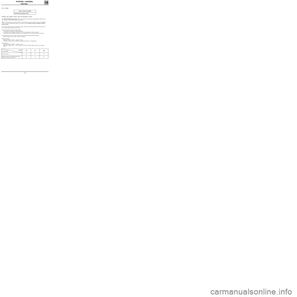
OPTIMA 5800 Diagnostic station
CHECKING THE CHARGING CIRCUIT USING THE DIAGNOSTIC STATION
The OPTIMA 5800 diagnostic station allows the alternator to be checked by measuring the voltage and cur-
rent delivered , with or without electrical consumers .
NOTE : the Amps clamp used for this station is of the inductive type (measurement range: 0 to 1 000 A). It
is fitted without disconnecting the battery, which allows the the computer memory and adaptive informa-
tion to be saved.
Fit the Amps clamp directly at the alternator output, with the arrow pointing towards the alternator (any in-
correct positioning is detected by the station).
The measurement is carried out in three stages :
- measurement of the battery voltage, ignition off,
- measurement of the regulated voltage and of the current supplied, without consumers,
- measurement of the regulated voltage and current supplied, with a maximum number of consumers.
On completion of the test, the values noted will lead to the following fault finding messages :
- Battery voltage, no load < 12.3 V = battery uncharged.
Without consumers :
- Regulated voltage > 14,8 V = > regulator faulty ,
- (regulated voltage, no load < 13.2 V) or (charging current< 2 A) = >charging fault.
With consumers :
- Regulated voltage > 14.8 V = > regulator faulty,
- Regulated voltage < 12.7 V = > it is necessary to check the alternator supply in relation to its specifica-
tions :
Engine
Current (amps)D7F E7J F8Q
Nominal current 70 75 75
Minimum current which the alternator must
supply, all consumers connected 53 51 55
FAULT FINDING
SPECIAL TOOLING REQUIRED
16-3