Page 57 of 105

STEERING ASSEMBLY
Power assisted steering rack
36
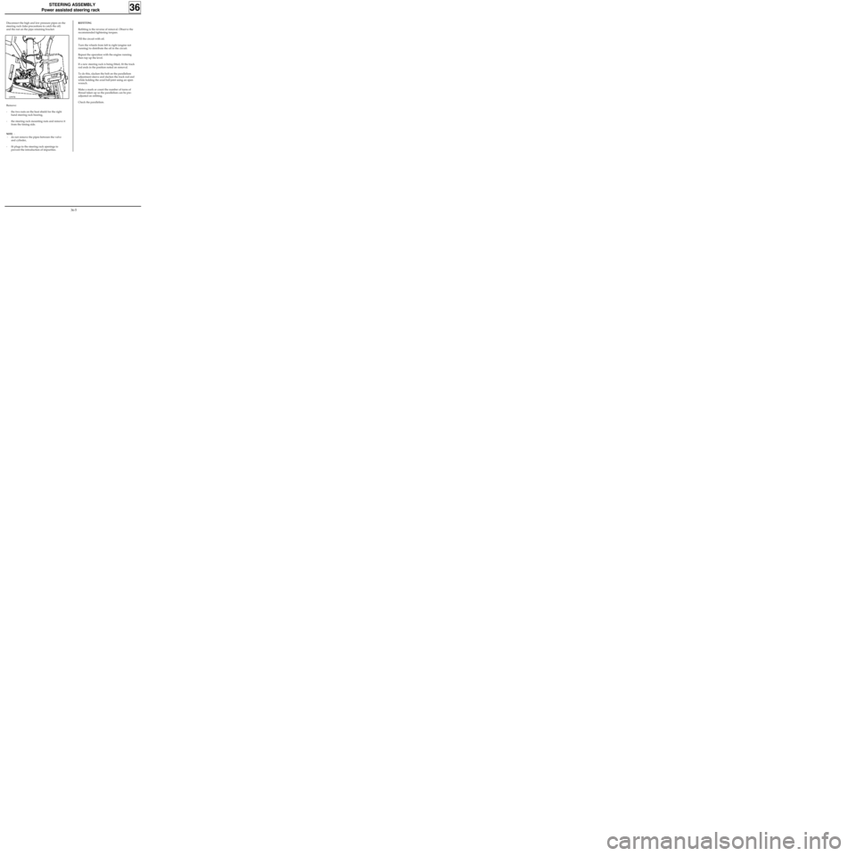
Disconnect the high and low pressure pipes on the
steering rack (take precautions to catch the oil)
and the nut on the pipe retaining bracket.
Remove:
- the two nuts on the heat shield for the right
hand steering rack bearing,
- the steering rack mounting nuts and remove it
from the timing side.
NOTE :
- do not remove the pipes between the valve
and cylinder,
- fit plugs to the steering rack openings to
prevent the introduction of impurities.
12997R
REFITTING
Refitting is the reverse of removal. Observe the
recommended tightening torques.
Fill the circuit with oil.
Turn the wheels from left to right (engine not
running) to distribute the oil in the circuit.
Repeat the operation with the engine running
then top up the level.
If a new steering rack is being fitted, fit the track
rod ends in the position noted on removal.
To do this, slacken the bolt on the parallelism
adjustment sleeve and slacken the track rod end
while holding the axial ball joint using an open
wrench.
Make a mark or count the number of turns of
thread taken up so the parallelism can be pre-
adjusted on refitting.
Check the parallelism.
36-5
Page 69 of 105

MECHANICAL ELEMENT CONTROLS
Master cylinder
37
Hydraulic pipe unions 1.7
Mounting nut on brake servo 1.8
REMOVAL
Disconnect the battery.
Disconnect the brake fluid level detector
connector.
Remove the injection computer (depending on
version).
Release the PAS reservoir and move it to the side,
towards the engine.
Drain and remove, by pulling up, the brake fluid
reservoir (take care to catch the fluid which will
run out).
Remove:
- the pipes and note their positions,
- the two mounting nuts on the brake servo.
REFITTING
Refitting is the reverse of removal.
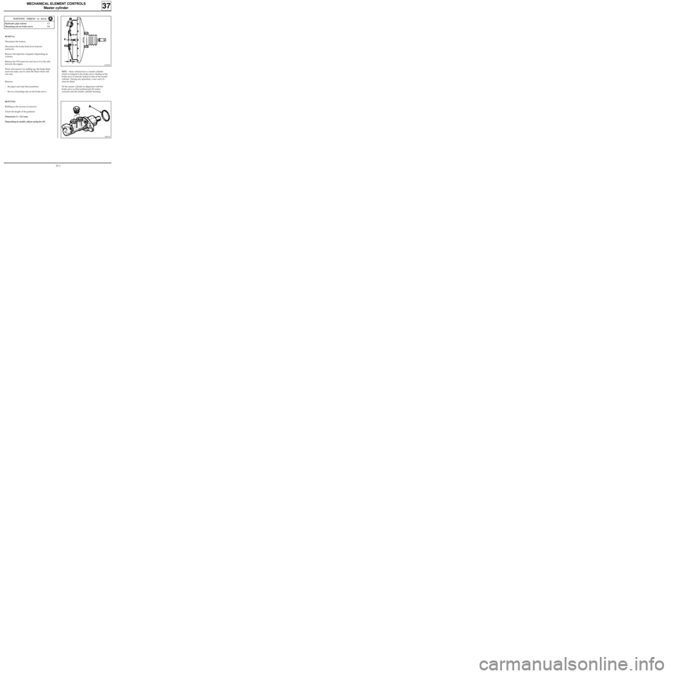
Check the length of the pushrod.
Dimension X = 22.3 mm.
Depending on model, adjust using pin (P).
91101R
NOTE : these vehicles have a master cylinder
which is integral to the brake servo. Sealing of the
brake servo is directly linked to that of the master
cylinder. During any operation, a new seal (A)
must be fitted.
Fit the master cylinder in alignment with the
brake servo so that pushrod pin (P) enters
correctly into the master cylinder housing.
TIGHTENING TORQUES (in daN.m)
DI3718
37-1
Page 71 of 105
MECHANICAL ELEMENT CONTROLS
Brake servo
TIGHTENING TORQUES (in daN.m)
Mounting nut on brake servo 1.8
Brake servo on bulkhead 2.3
- remove the 4 brake servo mounting nuts,
- remove the brake servo.
REFITTING
Before refitting, check:
-dimension L = 104.8 mm ,
-dimension X = 22.3 mm .The brake servo cannot be repaired. Operations
are only allowed on:
- the air filter,
- the non-return valve.
REMOVAL
Disconnect and remove the battery.
Remove:
- the master cylinder (following the method
described previously),
- the battery protection plate (4 bolts, 1 nut),
- the two mounting nuts for the expansion
bottle and move it towards the engine.
Disconnect the flexible vacuum hose from the
brake servo.
In the passenger compartment:
- remove the pin ( A ) from the clevice
connecting the brake pedal to the pushrod by
moving the clip,
37
91101R2
97860R
Refitting is the reverse of removal.
Bleed the brake circuit.
37-3
Page 72 of 105

SPECIAL TOOLING REQUIRED
Mot 453 -01 Hose clamp pliers
MECHANICAL ELEMENT CONTROLS
Brake servo
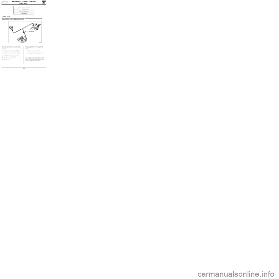
The sealing of the brake servo is checked on the
vehicle when the hydraulic circuit is in operating
condition.
Connect the vacuum pump between the brake
servo and the vacuum source (inlet manifold)
using a "T" union and the shortest possible pipe.
Run the engine at idle speed for one minute.
Clamp the pipe (clamp Mot. 453-01) between the
"T" union and the vacuum source.
Turn the engine off.If the vacuum drops by more than 33 mbar (25
mm/Hg) in 15 seconds, there is a leak located
either :
- at the non-return valve (replace it),
- or at the pushrod diaphragm (replace the
brake servo).
If the brake servo is not operational the braking
system will operate but the force required at the
pedal to obtain the equivalent deceleration as for
assisted braking is considerably higher .
CHECKING SEALING
When checking the sealing of the brake servo, ensure the seal between the brake servo and the master
cylinder is perfect. If there is a leak, replace the seal (A).
37
DI3701
EQUIPMENT REQUIRED
Vacuum pump
Petrol engine
37-4
Page 74 of 105
MECHANICAL ELEMENT CONTROLS
Vacuum pump
37
REMOVAL
Drain the cooling circuit.
Remove the air tube and its mounting.
Disconnect the quick release vacuum pipe.
Remove the thermostat mounting (2 bolts).
Remove the vacuum pump (2 bolts, 2 nuts).
13097-1S
Systematically renew the drive dog when repla-
cing the pump.
REFITTING
Refitting is the reverse of removal.
Bleed the brake circuit.
CHECKING
Engine warm, at 4000 rpm, the minimum vacuum
should be 700 mbar (525 mm/Hg) in 3 seconds.
Diesel engine
37-6
Page 90 of 105

MECHANICAL ELEMENT CONTROLS
Clutch control cable
37
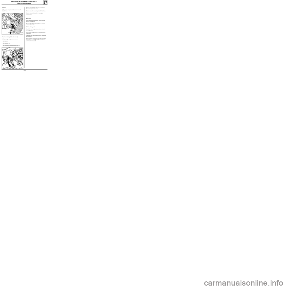
REMOVAL
In the engine compartment, disconnect the cable
from the fork.
89204S
12986R
Remove the end of the cable from its location on
the wear compensation sector.
Remove the cable sleeve stop from the bulkhead.
Remove the complete cable via the engine
compartment.
REFITTING
From the engine compartment, thread the cable
through the bulkhead.
Fit the cable end piece into position on the wear
compensation sector.
Refit the clutch pedal.
Check the wear compensation ratchets return to
the rest position.
In the engine compartment, fit the cable onto the
clutch fork.
Check the cable sleeve stop is correctly aligned on
the bulkhead.
Press the clutch pedal to clip the cable sleeve stop
into position on the bulkhead. The adjustment is
carried out automatically.
Press the pedal to pull the cable through.
In the passenger compartment, remove:
- the bolt ( 1 ),
- the stiffener ( 2 ),
- the nut from the pedal mounting shaft ( 3 ).
37-22