Page 13 of 105

Brake fluid
78491R
GENERAL
Brake unions and pipes
30
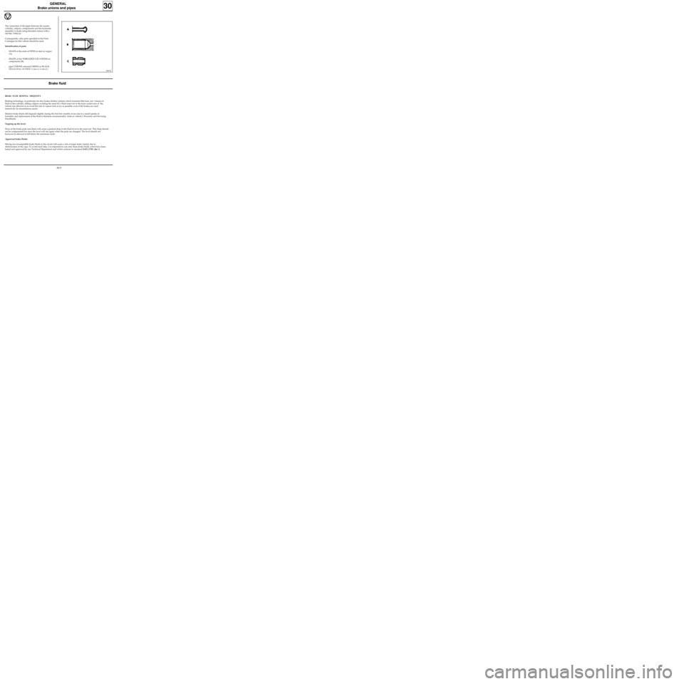
The connection of the pipes between the master
cylinder, calipers, compensator and the hydraulic
assembly is made using threaded unions with a
METRIC THREAD.
Consequently, only parts specified in the Parts
Catalogue for this vehicle should be used.
Identification of parts
- SHAPE of the ends of PIPES in steel or copper
(A),
- SHAPE of the THREADED LOCATIONS on
components (B),
- pipe UNIONS coloured GREEN or BLACK:
HEXAGONAL OUTSIDE 11 mm or 12 mm (C).
BRAKE FLUID RENEWAL FREQUENCY
Braking technology, in particular for disc brakes (hollow pistons which transmit little heat, low volume of
fluid in the cylinder, sliding calipers avoiding the need for a fluid reservoir in the least cooled area of the
wheel), has allowed us to avoid the risk of vapour lock as far as possible, even if the brakes are used
intensively (in mountainous areas).
Modern brake fluids still degrade slightly during the first few months of use due to a small uptake of
humidity and replacement of the fluid is therefore recommended (refer to vehicle’s Warranty and Servicing
Handbook).
Topping up the level:
Wear of the brake pads and shoes will cause a gradual drop in the fluid level in the reservoir. This drop should
not be compensated for since the level will rise again when the pads are changed. The level should not
however be allowed to fall below the minimum mark.
Approved brake fluids:
Mixing two incompatible brake fluids in the circuit will cause a risk of major leaks, mainly due to
deterioration of the cups. To avoid such risks, it is important to use only those brake fluids which have been
tested and approved by our Technical Department and which conform to standard SAE J 1703 dot 4.
30-9
Page 17 of 105
FRONT AXLE
Brake pads
31
REMOVAL
Disconnect the wear warning light wire (if fitted).
Push the piston back, sliding the caliper by hand.
Remove the lower brake caliper guide bolt.
SPECIAL TOOLING REQUIRED
Fre. 823 Tool for pushing piston back
Wheel bolts 9
Brake caliper guide bolt 4
12994R
REFITTING
Push back the caliper piston using tool Fre. 823.
Fit new brake pads.
The brake pad with the wear warning light wire
(if fitted) is fitted to the inside.
Refit the caliper into position and fit the lower
guide bolt.
Tighten the guide bolt to the recommended
torque 4 daN.m.
Reconnect the wear warning light wire (if fitted).
Press the brake pedal several times to bring the
piston into contact with the pads.
TIGHTENING TORQUES (in daN.m)
Pivot the caliper around the upper bolt.
Remove the brake pads.
Check:
- the condition and mounting of the piston dust
cover,
- the condition of the guide dust cover.
31-4
Page 41 of 105

REAR AXLE
Suspension bars, tubular rear axle
SPECIAL TOOLING REQUIRED
Emb. 880 Inertia extractor
TIGHTENING TORQUES (in daN.m)
Upper shock absorber mounting bolt 11.5
Lower shock absorber mounting bolt 8.5
REMOVAL
With the vehicle raised so its wheels hang free, re-
move the shock absorber on the side in question.
Remove the bar from the side, using tool
Emb. 880.
REFITTING
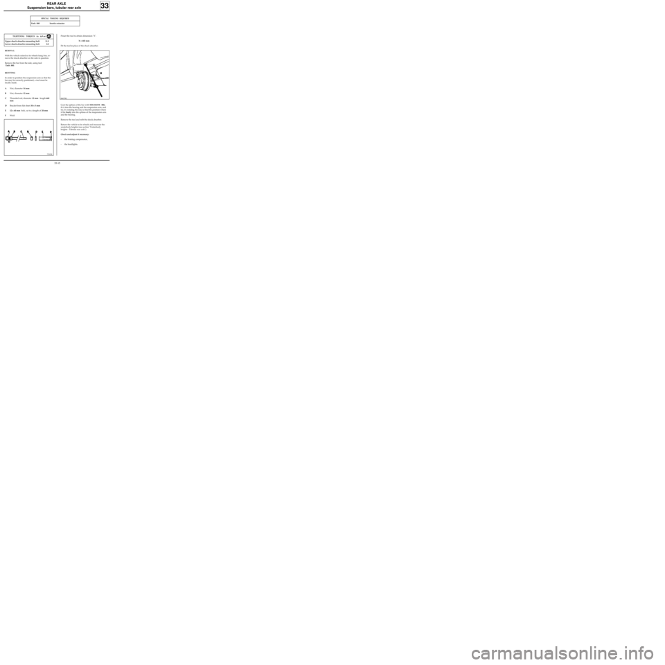
In order to position the suspension arm so that the
bar may be correctly positioned, a tool must be
locally made.
ANut, diameter 14 mm
BNut, diameter 12 mm
CThreaded rod, diameter 12 mm - length 660
mm
DBracket from flat sheet 30 x 5 mm
E 12 x 60 mm bolt, cut to a length of 20 mm
FWeld
33
75505R
Preset the tool to obtain dimension "X".
X = 402 mm
Fit the tool in place of the shock absorber.
88637R2
Coat the splines of the bar with MOLYKOTE BR2,
fit it into the bearing and the suspension arm, and
try, by rotating the rod, to find the position where
it fits freely into the splines of the suspension arm
and the bearing.
Remove the tool and refit the shock absorber.
Return the vehicle to its wheels and measure the
underbody heights (see section "Underbody
heights - Tubular rear axle").
Check and adjust if necessary:
- the braking compensator,
- the headlights.
33-15
Page 45 of 105
REAR AXLE
Four bar rear axle
33
Check and if necessary adjust:
- the braking compensator,
- the headlights.
REMINDER
When adjusting for a wheel height difference
between the right and left hand sides, always
make the adjustment on the anti-roll bars.
The adjustment for a difference in dimension " X"
between the right and left hand sides should
always be made on the suspension bars.
33-19
Page 54 of 105
STEERING ASSEMBLY
Axial ball joint
36
REFITTING
Assembly (2) MUST be renewed systematically.
83510-1R3
Refit to the rack (3) :
- the stop washer assembled with the locking
ring (2),
- the new axial ball joint (1) having lightly coated
the threads with
LOCTITE FREN-BLOC, ensuring
that the air evacuation opening is not blocked.
Before finally tightening the axial ball joint using
tool Dir. 1305-01, check that the tabs on the
locking ring (2) align with the flats (B) on the rack.
Tighten the axial ball joint to the recommended
torque.
Centre the steering to equalise the air in the
gaiters.
Fit a new gaiter and secure it with a new clip
(after greasing the gaiter bearing surface on the
axial ball joint).
Checking
Gently press on the gaiter to check the other
gaiter inflates which indicates the air is circulating
correctly.
36-2
Page 68 of 105

STEERING ASSEMBLY
Steering column
36
IMPORTANT : if these instructions are not
followed exactly the system may not operate
normally and could even be triggered incorrectly.
IMPORTANT
Before reconnecting the driver’s airbag cushion,
check to see if the system is operating correctly as
follows:
•check the airbag warning light on the
instrument panel is illuminated when the
ignition is on,
•connect a dummy ignition module to the
driver’s airbag connector and check that the
warning light extinguishes,
•switch the ignition off, connect the airbag
cushion in place of the dummy ignition module
and secure the cushion to the steering wheel,
•switch the ignition on. Check the warning light
illuminates for three seconds when the ignition
is switched on then extinguishes and remains
extinguished.
If the warning light does not operate as described
above, refer to the fault finding section and check
the system using the
XRBAG (Elé. 1288).
SPECIAL NOTES FOR VEHICLES FITTED WITH A
DRIVER’S AIRBAG
Ensure that the wheels are still straight.
Check that the rotary switch is still immobilised
before refitting.
If it is not, follow the method for centring
described in section 88 "driver’s airbag".
Renew the steering wheel bolt each time it is
removed ( pre-bonded bolt).
Observe the correct tightening torque ( 4.5
daN.m).
36-16
Page 97 of 105
ELECTRONICALLY CONTROLLED HYDRAULIC SYSTEMS
BOSCH ABS
38
PRN3818
LOCATION OF THE BOSCH ABS COMPONENTS
1Hydraulic assembly
2Master cylinder
3Brake servo4Brake fluid level warning light
5Braking compensator
38-2
Page 100 of 105
WIRING DIAGRAM KEY
104Ignition switch
118 ABS computer
150Rear right wheel sensor
151Rear left wheel sensor
152Front right wheel sensor
153Front left wheel sensor
160Stop switch
225Diagnostic socket
247Instrument panel
260Fuse box
777Power feed fuse board
R2Dashboard / rear left
R36ABS / Dashboard
R101Right hand side member / Right hand
headlight
ELECTRONICALLY CONTROLLED HYDRAULIC SYSTEMS
BOSCH ABS
38
38-5