Page 1799 of 4133
Fig. 205: Identifying CD Player Components
Fig. 206: Identifying CD Player Components
Remove/Install
1Open tailgate
2Open cover (1) and
remove
3Loosen butterfly screw (2)
for mount (3)
4Remove bolts (4).
5Pull CD player with
changer (in trunk) (A2/6)
forward
6Disconnect electrical plug
(8)
7Remove CD player with
changer Installation: Ensure
that the vertical
installation position is set
on the side of the CD
player.
8Unhook electric lead (5)
from retaining clips (6)
9Unscrew screws (7) and
remove CD player with
changer from mount
10Install in the reverse order
11Perform a function test
2001 Mercedes-Benz ML320
1998-2005 ACCESSORIES & BODY, CAB Electrical System - Body - 163 Chassis
me
Saturday, October 02, 2010 3:30:10 PMPage 304 © 2006 Mitchell Repair Information Company, LLC.
Page 1833 of 4133
Fig. 239: Identifying Antenna Diplexer, Antenna Line And GPS Antenna Lead
RETROFIT FIBER OPTIC CABLE WIRING HARNESS - AN82.70-P-0002-01GH
Connection diagram of fiber optic cable
1. Prepare fiber optic cable wiring harness (30) as shown in figure.
The vehicle is preinstalled with a fiber optic cable for the CD player with changer. This fiber optic
cable is tied back in the radio slot and is not required in this case.
Fig. 240: Identifying Connection Diagram Of Fiber Optic Cable
2. Connect fiber optic cable wiring harness (30) to the CTEL interface (A34/4).
3. After installing CTEL interface (A34/4) in the center console, route fiber optic cable wiring harness (30)
into the radio slot.
4. Connect wiring harness when installing radio (A2) or COMAND (A40/3).
2001 Mercedes-Benz ML320
1998-2005 ACCESSORIES & BODY, CAB Electrical System - Body - 163 Chassis
me
Saturday, October 02, 2010 3:30:11 PMPage 338 © 2006 Mitchell Repair Information Company, LLC.
Page 1844 of 4133

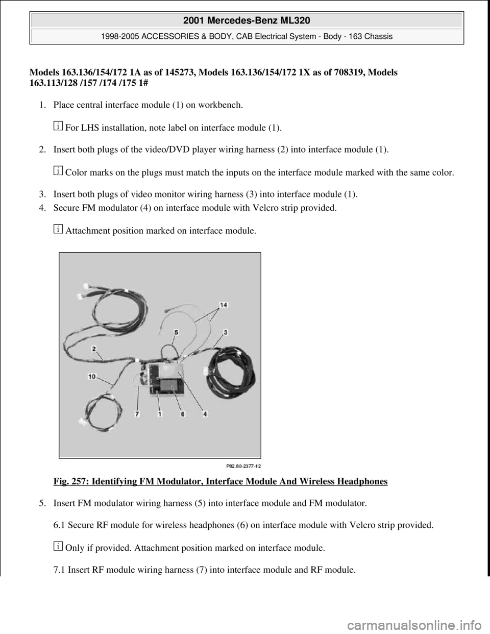
Models 163.136/154/172 1A as of 145273, Models 163.136/154/172 1X as of 708319, Models
163.113/128 /157 /174 /175 1#
1. Place central interface module (1) on workbench.
For LHS installation, note label on interface module (1).
2. Insert both plugs of the video/DVD player wiring harness (2) into interface module (1).
Color marks on the plugs must match the inputs on the interface module marked with the same color.
3. Insert both plugs of video monitor wiring harness (3) into interface module (1).
4. Secure FM modulator (4) on interface module with Velcro strip provided.
Attachment position marked on interface module.
Fig. 257: Identifying FM Modulator, Interface Module And Wireless Headphones
5. Insert FM modulator wiring harness (5) into interface module and FM modulator.
6.1 Secure RF module for wireless headphones (6) on interface module with Velcro strip provided.
Only if provided. Attachment position marked on interface module.
7.1 Insert RF module wirin
g harness (7) into interface module and RF module.
2001 Mercedes-Benz ML320
1998-2005 ACCESSORIES & BODY, CAB Electrical System - Body - 163 Chassis
me
Saturday, October 02, 2010 3:30:11 PMPage 349 © 2006 Mitchell Repair Information Company, LLC.
Page 1845 of 4133

If fitted.
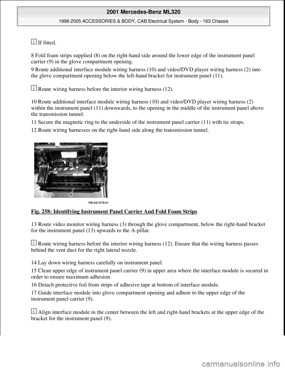
8 Fold foam strips supplied (8) on the right-hand side around the lower edge of the instrument panel
carrier (9) in the glove compartment opening.
9 Route additional interface module wiring harness (10) and video/DVD player wiring harness (2) into
the glove compartment opening below the left-hand bracket for instrument panel (11).
Route wiring harness before the interior wiring harness (12).
10 Route additional interface module wiring harness (10) and video/DVD player wiring harness (2)
within the instrument panel (11) downwards, to the opening in the middle of the instrument panel above
the transmission tunnel.
11 Secure the magnetic ring to the underside of the instrument panel carrier (11) with tie straps.
12 Route wiring harnesses on the right-hand side along the transmission tunnel.
Fig. 258: Identifying Instrument Panel Carrier And Fold Foam Strips
13 Route video monitor wiring harness (3) through the glove compartment, below the right-hand bracket
for the instrument panel (13) upwards to the A-pillar.
Route wiring harness before the interior wiring harness (12). Ensure that the wiring harness passes
behind the vent duct for the right lateral nozzle.
14 Lay down wiring harness carefully on instrument panel.
15 Clean upper edge of instrument panel carrier (9) in upper area where the interface module is secured in
order to ensure maximum adhesion.
16 Detach protective foil from strips of adhesive tape at bottom of interface module.
17 Guide interface module into glove compartment opening and adhere to the upper edge of the
instrument panel carrier (9).
Align interface module in the center between the left and right-hand brackets at the upper edge of the
bracket for the instrument panel (9).
2001 Mercedes-Benz ML320
1998-2005 ACCESSORIES & BODY, CAB Electrical System - Body - 163 Chassis
me
Saturday, October 02, 2010 3:30:11 PMPage 350 © 2006 Mitchell Repair Information Company, LLC.
Page 1870 of 4133
Fig. 288: Identifying Video Display, Video Monitor Unit And Remote Control Storage
Compartment
RETROFIT WIRING HARNESS FOR AUXILIARY INTERFACE MODULE AND VIDEO/DVD PLAYER - AZ82.60-P-0004-
03A
Model 163.113/136 /154 /172 /174 #A as of 145273 289564,
Model 163.113 /136 /154 /172 #X as of 708319 up to 754619
1. Adhere supplied self-adhesive foamed material (1) to rear end of the center console bracket (2).
2. Measure dimension (a) on left and right from the upper edge of the transmission tunnel and mark floor
covering.
3. Starting from the transmission tunnel cutout of the floor covering, cut into floor covering 2 times (b).
Incisions should be located above the recesses in the transmission tunnel.
2001 Mercedes-Benz ML320
1998-2005 ACCESSORIES & BODY, CAB Electrical System - Body - 163 Chassis
me
Saturday, October 02, 2010 3:30:12 PMPage 375 © 2006 Mitchell Repair Information Company, LLC.
Page 1871 of 4133
Fig. 289: Identifying Dimension (A) On Left And Right From Upper Edge Of Transmission Tunnel
4. From the transmission tunnel cutout of the floor covering measure dimension (c) and from the inner edge
of the cutout of the 40 % rear seat (3) measure the dimension (d) and mark floor covering.
Fig. 290: Identifying Transmission Tunnel Cutout Of Floor Covering Dimension (C)
5. Cut into floor covering toward left-hand side (e).
Incision should be located in the center of the transmission tunnel.
6. Starting from the center of the previous incision, cut into floor covering toward the rear (f).
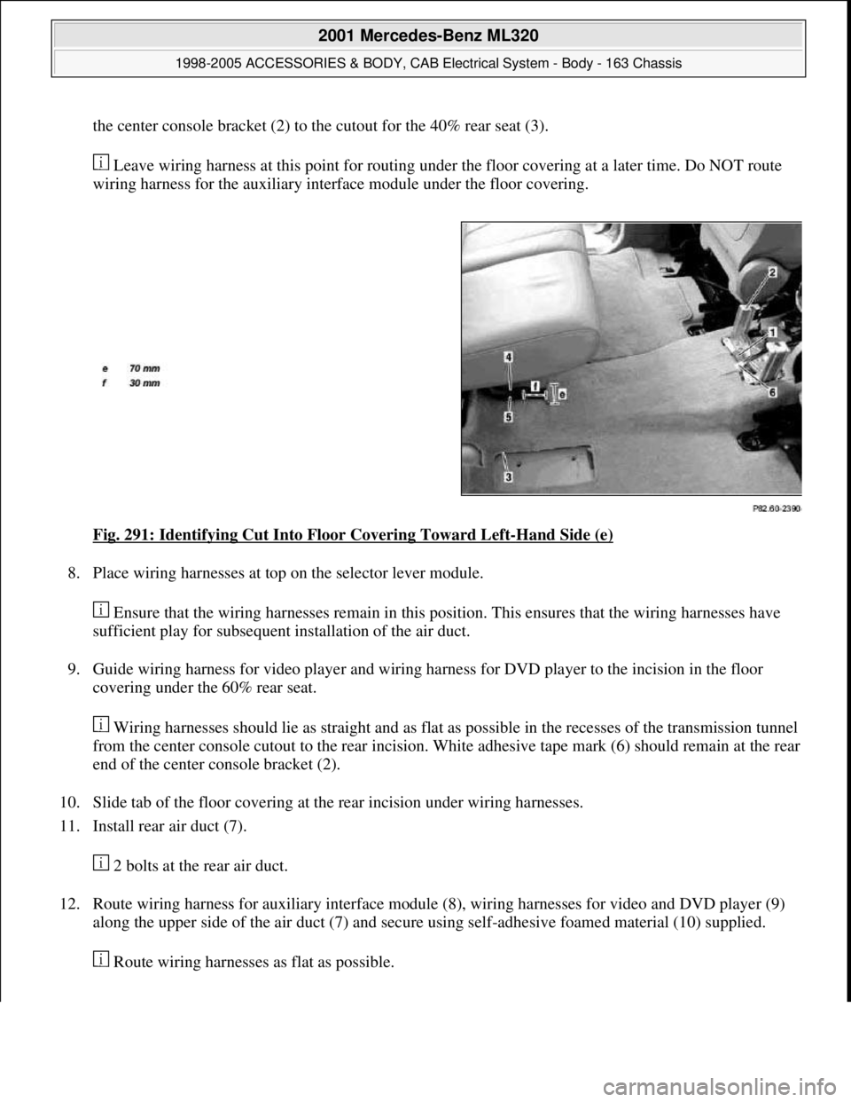
7. Guide wiring harness for video player (4) and wiring harness for DVD player (5) from the incision behind
2001 Mercedes-Benz ML320
1998-2005 ACCESSORIES & BODY, CAB Electrical System - Body - 163 Chassis
me
Saturday, October 02, 2010 3:30:12 PMPage 376 © 2006 Mitchell Repair Information Company, LLC.
Page 1872 of 4133

the center console bracket (2) to the cutout for the 40% rear seat (3).
Leave wiring harness at this point for routing under the floor covering at a later time. Do NOT route
wiring harness for the auxiliary interface module under the floor covering.
Fig. 291: Identifying Cut Into Floor Covering Toward Left
-Hand Side (e)
8. Place wiring harnesses at top on the selector lever module.
Ensure that the wiring harnesses remain in this position. This ensures that the wiring harnesses have
sufficient play for subsequent installation of the air duct.
9. Guide wiring harness for video player and wiring harness for DVD player to the incision in the floor
covering under the 60% rear seat.
Wiring harnesses should lie as straight and as flat as possible in the recesses of the transmission tunnel
from the center console cutout to the rear incision. White adhesive tape mark (6) should remain at the rear
end of the center console bracket (2).
10. Slide tab of the floor covering at the rear incision under wiring harnesses.
11. Install rear air duct (7).
2 bolts at the rear air duct.
12. Route wiring harness for auxiliary interface module (8), wiring harnesses for video and DVD player (9)
along the upper side of the air duct (7) and secure using self-adhesive foamed material (10) supplied.
Route wirin
g harnesses as flat as possible.
2001 Mercedes-Benz ML320
1998-2005 ACCESSORIES & BODY, CAB Electrical System - Body - 163 Chassis
me
Saturday, October 02, 2010 3:30:12 PMPage 377 © 2006 Mitchell Repair Information Company, LLC.
Page 1873 of 4133
Fig. 292: Identifying Rear Air Duct, Self-Adhesive Foamed Material And Auxiliary Interface
Module
13. Secure wiring harness for auxiliary interface module (8) with tie straps (12) to wiring harness of the rear
power window (11).
White adhesive tape marks identify position of the tie straps.
14. Secure video player wiring harness with blue color coding (4) and DVD player wiring harness with red
color coding (5) with self-adhesive brackets (13) and tie straps at the 60% rear seat.
The white strips of adhesive tape on the wiring harness for video player (4) and the red strips of
adhesive tape on the wiring harness for DVD player (5) identify the location for the brackets and tie
straps.
2001 Mercedes-Benz ML320
1998-2005 ACCESSORIES & BODY, CAB Electrical System - Body - 163 Chassis
me
Saturday, October 02, 2010 3:30:12 PMPage 378 © 2006 Mitchell Repair Information Company, LLC.