1997 MERCEDES-BENZ ML500 oil
[x] Cancel search: oilPage 3229 of 4133
3. To install, reverse removal procedure. Use NEW "O" rings lubricated with refrigerant oil. If installing a
new or repaired condenser, add 0.68 ounce of NEW refrigerant oil to condenser. Tighten refrigerant line
bolts to specification. See TORQUE SPECIFICATIONS.
2001 Mercedes-Benz ML320
2000-01 MANUAL A/C-HEATER SYSTEMS ML 320, ML 430 & ML 55
me
Saturday, October 02, 2010 3:25:10 PMPage 18 © 2006 Mitchell Repair Information Company, LLC.
Page 3232 of 4133
Fig. 6: Removing Cooling Fans & Condenser
Courtesy of MERCEDES-BENZ OF NORTH AMERICA.
COOLING FANS
Removal & Installation
Remove headlight units. Remove upper frame crossmember, release hood release control cable and remove
crossmember. See Fig. 6
. Remove 2 cooling fans frame bolts on radiator. Disconnect cooling fan connector.
Release outside temperature sensor wiring harness. Pull up on cooling fan and remove. To install, reverse
removal procedure. Ensure cooling fan bottom guides are properly seated in lower mounts.
EVAPORATOR
Removal & Installation
Remove A/C housing unit. See A/C HOUSING UNIT . Remove expansion valve. See Fig. 5 . Discard "O"
rings. Disassemble A/C housing unit. Remove evaporator. Remove evaporator temperature sensor. To install,
reverse removal procedure. Use NEW "O" rings lubricated with refrigerant oil. If installing a new or repair
evaporator, add 1.35 ounces of NEW refrigerant oil to evaporator.
EXPANSION VALVE
Removal & Installation
1. Discharge A/C system, using approved refrigerant recovery/recycling equipment. Without disconnecting
coolant hoses, remove coolant expansion reservoir and set aside. Remove refrigerant line bracket and
loosen clamps. See Fig. 5
. Pull refrigerant lines out of expansion valve.
2. Remove expansion valve self-locking nut and discard. Remove expansion valve. Discard "O" rings. To
install, reverse removal procedure. Use NEW "O" rings lubricated with refrigerant oil. Tighten NEW self-
locking nut to specification. See TORQUE SPECIFICATIONS
.
INSTRUMENT PANEL & INSTRUMENT PANEL CARRIER
Removal & Installation
1. Secure vehicle against rolling. Set transmission selector to "D" position. Obtain radio security code.
Disconnect negative battery cable. Remove driver-side air bag.
2. Place match marks on steering wheel and steering shaft. Remove steering wheel, upper steering column
covers and combination switch. Remove instrument cluster cover frame. Remove one instrument panel
lower section bolt.
3. Remove screws in footwell from left side of instrument panel bottom section. Remove instrument panel
center section. Remove 4 A/C control panel screws and remove control panel. See Fig. 1
. Release pull
cables and disconnect connectors.
4. Remove screws from center section. Remove glove box. Remove screws in footwell from right side of
instrument panel bottom section. Remove entry courtesy lights. Remove end covers and screws.
5. Release 4 "A" clips between instrument panel bottom section and upper section. See Fig. 7
. Release
parkin
g brake release cable from handle. With assistance, remove instrument panel bottom section.
2001 Mercedes-Benz ML320
2000-01 MANUAL A/C-HEATER SYSTEMS ML 320, ML 430 & ML 55
me
Saturday, October 02, 2010 3:25:10 PMPage 21 © 2006 Mitchell Repair Information Company, LLC.
Page 3236 of 4133
Fig. 9: Replacing Intake Air Dust Filter
Courtesy of MERCEDES-BENZ OF NORTH AMERICA.
RECEIVER-DRIER
Removal & Installation
1. Discharge A/C system, using approved refrigerant recovery/recycling equipment. Remove headlight
units. Remove headlight units. Remove upper frame crossmember, release hood release control cable and
remove crossmember. See Fig. 6
.
2. Remove bolts from receiver-drier refrigerant lines. See Fig. 5
. Disconnect refrigerant lines from receiver-
drier. Plug exposed openings to protect A/C system from debris and moisture. Discard "O" rings. Loosen
receiver-drier clamp bolt. Remove receiver-drier. To install, reverse removal procedure.
3. When installing a new receiver-drier, add 0.34 ounce of NEW refrigerant oil to receiver-drier. Use NEW
"O" rings. Tighten refrigerant line bolts to specification. See TORQUE SPECIFICATIONS
.
TORQUE SPECIFICATIONS
TORQUE SPECIFICATIONS
WIRING DIAGRAMS
ApplicationFt. Lbs. (N.m)
Compressor Mounting Bolts15 (20)
Refrigerant Line-To-Compressor Bolt15 (20)
Refrigerant Line-To-Condenser Bolt15 (20)
Steering Column Bolt15 (20)
Steering Column Nut13 (18)
INCH Lbs. (N.m)
Expansion Valve Self-Locking Nut89 (10)
Refrigerant Line-To-Receiver-Drier Bolt89 (10)
2001 Mercedes-Benz ML320
2000-01 MANUAL A/C-HEATER SYSTEMS ML 320, ML 430 & ML 55
me
Saturday, October 02, 2010 3:25:10 PMPage 25 © 2006 Mitchell Repair Information Company, LLC.
Page 3248 of 4133
All models fitted with air conditioning
Do not carry repair operations out on the air conditioning circuit in the open air during moist weather.
Moisture in the refrigerant circuit reduces the system's refrigeration output and leads to damage to the
components. The acidic substances produced by moisture within the system decompose the desiccant in the
fluid reservoir and damage the entire system.
After separating/unscrewing refrigerant lines, immediately seal off the connection openings so that they are
airproof using suitable stop plugs (parts kit).
Replace the fluid reservoir every time you open up the refrigeration circuit.
Always store all spare components in a dry, sealed-off area. Do not remove stop plugs in new components until
just before they are installed. Use special care when handling the receiver/dryer with its integral desiccation
unit.
When a receiver/dryer is left open, the dryer unit quickly becomes saturated with moisture, rendering it useless.
Check drier cartridge packaging for damage. Dispose of drier cartridges with damaged packaging.
Install the desiccant cartridge no later than 20 minutes after opening the packaging.
Further protection against moisture is provided by carefully evacuating the air conditioning system following
repair operations. By generating vacuum in the system, the evacuation process removes any moisture that might
have penetrated into the system.
NOTES ON RETROFITTING AN AIR CONDITIONING SYSTEM - AH83.30-P-0001-02A
Do not remove the plugs on any of the components until immediately prior to installation.
Fit all AC lines with new sealing rings. Coat thread and sealing rings with compressor oil.
BASIC KNOWLEDGE
VENTILATION, FUNCTION - GF83.10-P-2000GH
MODEL 163 up to 31.8.01
2001 Mercedes-Benz ML320
1998-2005 HVAC Climate Control - 163 Chassis
me
Saturday, October 02, 2010 3:23:14 PMPage 4 © 2006 Mitchell Repair Information Company, LLC.
Page 3344 of 4133
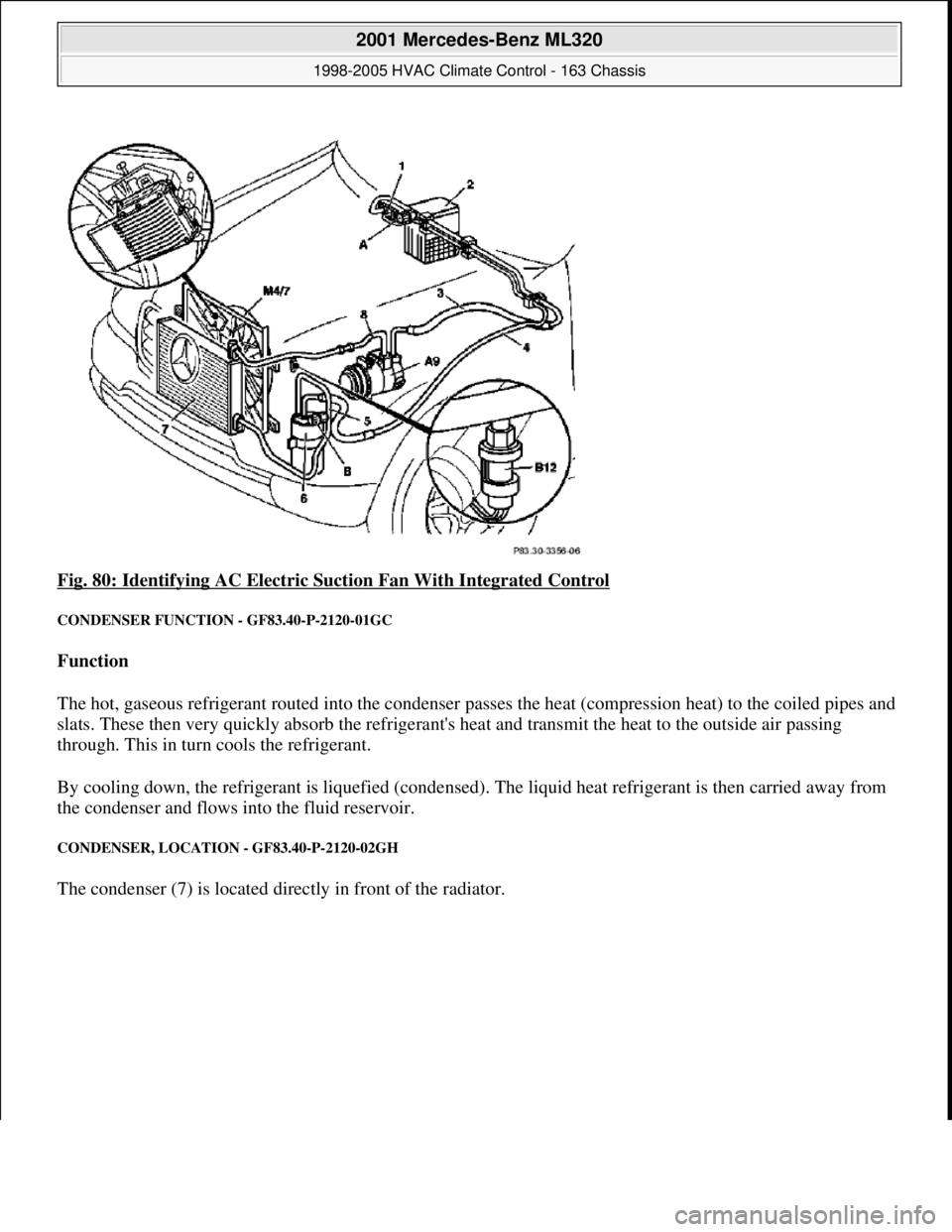
Fig. 80: Identifying AC Electric Suction Fan With Integrated Control
CONDENSER FUNCTION - GF83.40-P-2120-01GC
Function
The hot, gaseous refrigerant routed into the condenser passes the heat (compression heat) to the coiled pipes and
slats. These then very quickly absorb the refrigerant's heat and transmit the heat to the outside air passing
through. This in turn cools the refrigerant.
By cooling down, the refrigerant is liquefied (condensed). The liquid heat refrigerant is then carried away from
the condenser and flows into the fluid reservoir.
CONDENSER, LOCATION - GF83.40-P-2120-02GH
The condenser (7) is located directly in front of the radiator.
2001 Mercedes-Benz ML320
1998-2005 HVAC Climate Control - 163 Chassis
me
Saturday, October 02, 2010 3:23:16 PMPage 100 © 2006 Mitchell Repair Information Company, LLC.
Page 3369 of 4133
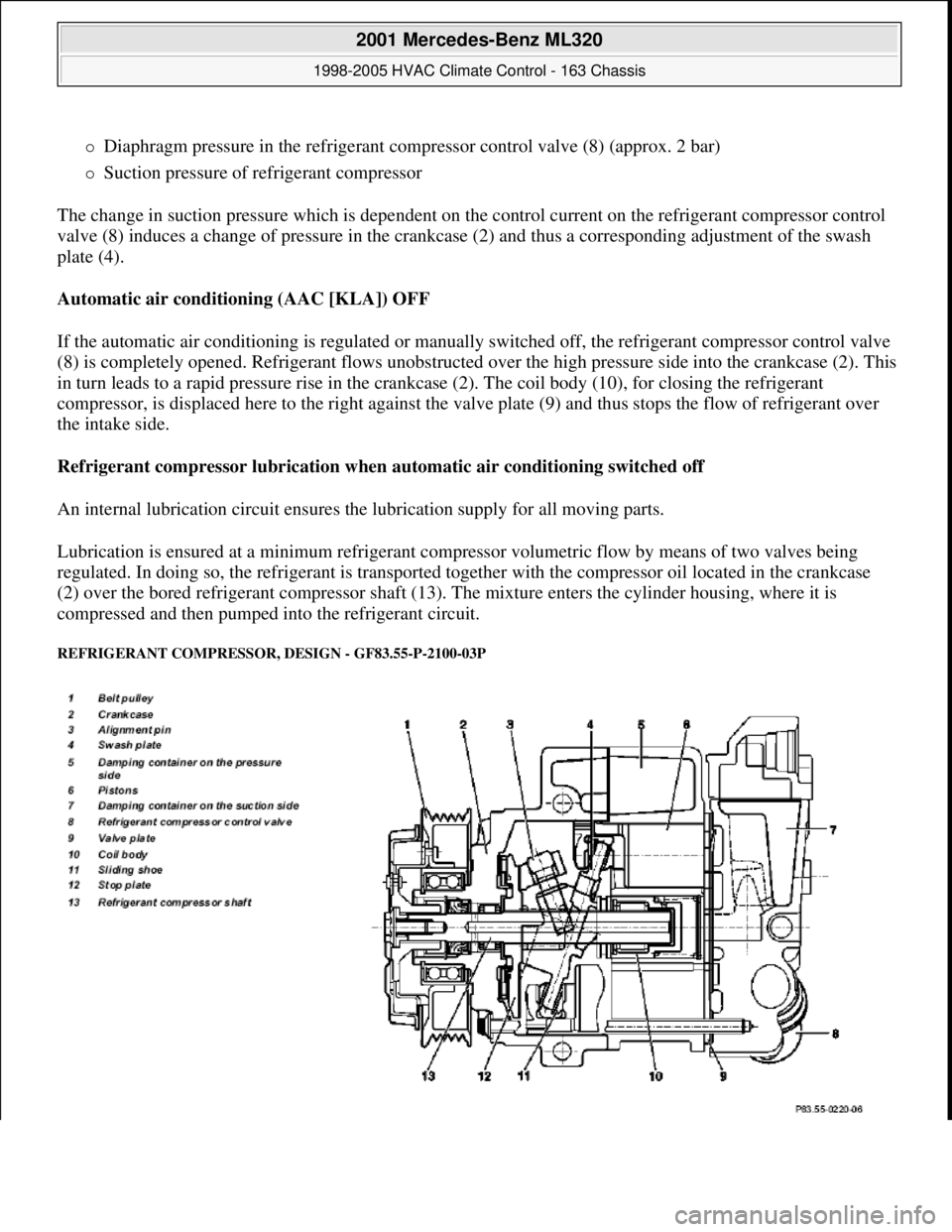
Diaphragm pressure in the refrigerant compressor control valve (8) (approx. 2 bar)
Suction pressure of refrigerant compressor
The change in suction pressure which is dependent on the control current on the refrigerant compressor control
valve (8) induces a change of pressure in the crankcase (2) and thus a corresponding adjustment of the swash
plate (4).
Automatic air conditioning (AAC [KLA]) OFF
If the automatic air conditioning is regulated or manually switched off, the refrigerant compressor control valve
(8) is completely opened. Refrigerant flows unobstructed over the high pressure side into the crankcase (2). This
in turn leads to a rapid pressure rise in the crankcase (2). The coil body (10), for closing the refrigerant
compressor, is displaced here to the right against the valve plate (9) and thus stops the flow of refrigerant over
the intake side.
Refrigerant compressor lubrication when automatic air conditioning switched off
An internal lubrication circuit ensures the lubrication supply for all moving parts.
Lubrication is ensured at a minimum refrigerant compressor volumetric flow by means of two valves being
regulated. In doing so, the refrigerant is transported together with the compressor oil located in the crankcase
(2) over the bored refrigerant compressor shaft (13). The mixture enters the cylinder housing, where it is
compressed and then pumped into the refrigerant circuit.
REFRIGERANT COMPRESSOR, DESIGN - GF83.55-P-2100-03P
2001 Mercedes-Benz ML320
1998-2005 HVAC Climate Control - 163 Chassis
me
Saturday, October 02, 2010 3:23:16 PMPage 125 © 2006 Mitchell Repair Information Company, LLC.
Page 3420 of 4133
Remove/install fresh
air/recirculated air stepper motorMODEL 163...AR83.30-P-
2010GH
Removing and installing
blending air increment
adjustment motor
MODEL 163...AR83.30-P-
2020GH
Remove and install evaporator
housingMODEL 163...AR83.30-P-
5200GH
Disassembling, assembling A/C
housingMODEL 163 with CODE (580) Air conditioning or, in
USA, Tempmatic A/CAR83.30-P-
5201GH
Correcting oil level in air
conditioning following repair or
slow refrigerant loss
MODEL 163, 202, 208, 210, 215, 220 ...AR83.30-P-
5251E
Correcting oil level in air
conditioning after replacing
parts
MODEL 163, 202, 208, 210, 215, 220 ...AR83.30-P-
5252E
Correcting oil level in air
conditioning after system
suddenly loses all refrigerant
MODEL 163, 202, 208, 210, 215, 220 ...AR83.30-P-
5253E
Remove and install expansion
valveMODEL 163...AR83.30-P-
5520GH
Remove/install evaporatorMODEL 163 with CODE (580) Air conditioning or
Tempmatic for USAAR83.30-P-
5540GH
Remove/install air conditioning
blower motorMODEL 163...AR83.30-P-
5560GH
Remove/install blower motor in
rearMODEL 163.113/154 /174 #A as of 289565, 163.113 #X
as of 754620, 163.128 /157 /175AR83.30-P-
5565GH
Remove/install auxiliary fanMODEL 163.136 /154 /157 /172 with CODE (580) Air
conditioning or Tempmatic for USAAR83.30-P-
5600GH
Remove and install
receiver/drierMODELS 163.113/136 /154 /157 /172 /174 /175 with
CODE (580) Air conditioning or Tempmatic for USAAR83.30-P-
6520GH
Remove and install
receiver/drierMODEL 163.128AR83.30-P-
6520GI
Install/remove condenserMODEL 163...AR83.30-P-
6540GH
Remove, install air conditioning
control moduleMODELS 163.113/136/154/172/174 up to 31.8.01 with
CODE (580) air conditioning or Tempmatic for USAAR83.30-P-
6600GH
Remove and install evaporator
temperature sensorMODEL 163 with CODE (580) Air conditioning or
Tempmatic for USAAR83.30-P-
8085GH
Remove/install outside air
temperature sensorMODEL 163...AR83.30-P-
8086GH
Remove/install air outlet
temperature sensorMODEL 163...AR83.30-P-
8087GH
Remove/install air outlet
temperature sensorMODEL 163...AR83.30-P-
8087GI
2001 Mercedes-Benz ML320
1998-2005 HVAC Climate Control - 163 Chassis
me
Saturday, October 02, 2010 3:23:17 PMPage 176 © 2006 Mitchell Repair Information Company, LLC.
Page 3432 of 4133
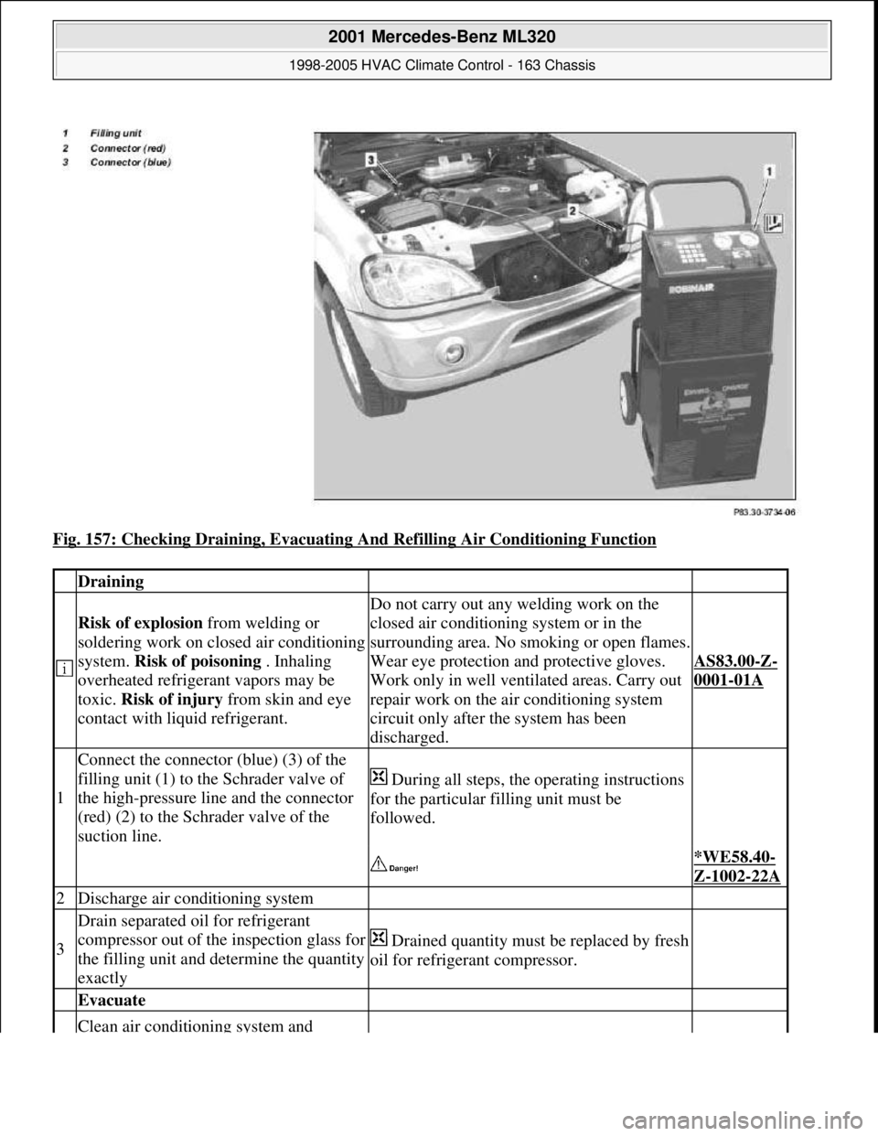
Fig. 157: Checking Draining, Evacuating And Refilling Air Conditioning Function
Draining
Risk of explosion from welding or
soldering work on closed air conditioning
system. Risk of poisoning . Inhaling
overheated refrigerant vapors may be
toxic. Risk of injury from skin and eye
contact with liquid refrigerant.
Do not carry out any welding work on the
closed air conditioning system or in the
surrounding area. No smoking or open flames.
Wear eye protection and protective gloves.
Work only in well ventilated areas. Carry out
repair work on the air conditioning system
circuit only after the system has been
discharged.
AS83.00-Z-
0001-01A
1
Connect the connector (blue) (3) of the
filling unit (1) to the Schrader valve of
the high-pressure line and the connector
(red) (2) to the Schrader valve of the
suction line.
During all steps, the operating instructions
for the particular filling unit must be
followed.
*WE58.40-
Z-1002-22A
2Discharge air conditioning system
3
Drain separated oil for refrigerant
compressor out of the inspection glass for
the filling unit and determine the quantity
exactly
Drained quantity must be replaced by fresh
oil for refrigerant compressor.
Evacuate
Clean air conditioning system and
2001 Mercedes-Benz ML320
1998-2005 HVAC Climate Control - 163 Chassis
me
Saturday, October 02, 2010 3:23:18 PMPage 188 © 2006 Mitchell Repair Information Company, LLC.