1997 MERCEDES-BENZ ML500 oil
[x] Cancel search: oilPage 3185 of 4133

AD54.30-P-2000-02GC
Notes on HHT previous knowledge diagnosis
IC
HHT :
The instrument cluster and active service system (ASSYST) sub-
function are checked with HHT, there being the choice of the
following functions for this:
1. Control module version
2. Fault memory
3. Actual values
4. Actuations
5. Control module adaptation
Additional information on test items 2, 3 and 5 can be called up using
the INPUT key
Control module adaptation
The following alternatives are available in the HHT under control
module adaptation:
1.)
Read out coding and transfer to new instrument cluster. IC and
ASSYST.
2.)
Read out/change codings e.g.:
Engine and national variants,
version of fuel tank,
special equipment etc.
3.)
Settings:
1
Clock
2
Put forward kilometer reading
3
Put back kilometer reading
4
Oil change
5
Reset oil change initiated inadvertently
6
Active Service System
7
Enter times with battery disconnected
8
Set minimum oil warning
Before replacing a defective instrument cluster, readout the existing
variant codings (driving data and instrument cluster data) and store in
the HHT on an interim basis. Read in the values stored on an interim
basis again after installing the new instrument cluster.
If it is not possible to read out the stored variant coding, all variant
codings must be input manually (menu-assistance in HHT).
When installing an instrument cluster on an experimental basis, do
not put forward the kilometer reading as it cannot be put back later.
Copyright DaimlerChrysler AG 05.06.2006 CD-Ausgabe G/10/04 . This WIS print-out will not be recorde
d by Modification services.
Page 1
Page 3189 of 4133

AF18.00-P-8045A
High oil consumption, blue smoke
26.10.99
ENGINE
112 in MODEL 129, 163, 202, 208, 210
ENGINE
112 in MODEL 463
Modification notes
18.11.99
Supersedes STIP 18.40-004 dated 5.11.97
Remedy revised
Damage code
Cause
Remedy
01 241 B2
Cast iron crust in oil drain duct on right
cylinder head, inner rear
1
Remove right cylinder head.
#
In case of complaint oil drain duct is filled
with engine oil.
Engine 112 in model 129, 202, 208, 210
AR01.30-P-5800B
Engine 112.942 in model 163.154
AR01.30-P-5800MV
Engine 112.945 in model 463
AR01.30-P-5800GV
2
Remove present cast iron crust.
Use sharp edged 10 mm punch. The cast
iron crust (approx. 11x17x1 mm) is located
approx. 50 mm below the upper cylinder head
separating surface.
3
Install right cylinder head
#
Engine 112 in model 129
AR01.30-P-5800B
Engine 112 in model 202, 208, 210
AR01.30-P-5800BA
Engine 112.942 in model 163.154
AR01.30-P-5800MV
Engine 112.945 in model 463
AR01.30-P-5800GV
Copyright DaimlerChrysler AG 20.05.2006 CD-Ausgabe G/10/04 . This WIS print-out will not be recorde
d by Modification services.
Page 1
Page 3190 of 4133

AF18.00-P-8044D
High oil consumption
12.3.01
ENGINE
112 in MODEL 129, 163, 170, 202, 203, 208, 210, 220
ENGINE
113 in MODEL 129, 163, 202, 208, 210, 215, 220
ENGINE
112, 113 in MODEL 463
Damage code
Cause
Remedy
Studies on engines 112/113 due to
excessive engine oil consumption have
indicated to date that excessive engine oil
consumption is not a general subject, but
rather can result from various causes.
The causes listed below may cause
excessive engine oil consumption individually
or in combination.
For commercially available tools for see
Workshop Equipment Manual
Cause 1:
Remedy 1:
00 001 70
Cast iron crust in right cylinder head behind
oil drain opening
1
Remove cast iron crust
AF18.00-P-8045A
Cause 2:
Remedy 2:
00 001 70
V-shaped material flaws (rough unhoned
points) on individual cylinder liners
Up to production 08/2000.
1
Check cylinder liners with piston at
bottom dead center.
#
Inspect cylinders with light probe
AR01.00-P-0200AU
*WH58.30-Z-1009-05A
*WH58.30-Z-1010-05A
*WH58.30-Z-1027-05A
Cylinder barrels not okay:
#
2
Remove/install/replace engine or
shortblock.
Cause 3:
Remedy 3:
00 001 70
Single oil scraper rings with ring tension at
lower tolerance limit.
Up to production 06/1999.
1
Perform oil consumption test drive over
approx. 500 km.
AR18.00-P-0025AV
Exclude all other types of faults.
2
Remove/install/replace piston rings.
Install cleaned pistons with new piston
rings in the same cylinder.
Install piston rings with optimized ring
tension.
These piston rings are available as
replacement parts under the normal
replacement part number.
Cause 4:
Remedy 4:
00 001 70
Individual (right) cylinder heads with inner
porous points to air injection duct.
1
Check left/right cylinder bank.
If a cylinder bank is oily:
#
2
Remove/install/replace only this cylinder
head.
ENGINE
112 in MODEL 220, 210, 208, 202,
129
ENGINE
113 in MODEL 220, 210, 208, 202,
129
AR01.30-P-5800B
ENGINE
112.942 in MODEL 163.154
ENGINE
113.942 in MODEL 163.172
ENGINE
113.981 in MODEL 163.174 AR01.30-P-5800MV
ENGINE
112.945, 113.962 in MODEL 463
AR01.30-P-5800GV
Cause 5:
Remedy 5:
00 001 70
Individual engines with missing valve seals on
individual cylinders
1
Remove valve springs on affected
cylinder.
AR05.30-P-3500B
In this case, usually one cylinder is oily, oil
runs through valve cone into cylinder when
valve is open.
2
Check valve seal.
Copyright DaimlerChrysler AG 20.05.2006 CD-Ausgabe G/10/04 . This WIS print-out will not be recorde
d by Modification services.
Page 1
Page 3191 of 4133

Valve seal not okay :
#
3
Remove/install/replace valve seal.
AR05.30-P-3500B
Cause 6:
Remedy 6:
00 001 70
1.5 mm hole missing on individual right
cylinder head covers at connection to
crankcase ventilation.
1
Check cylinder head cover
Up to production 06/1999.
Crankcase ventilation out of order, engine can
sludge up and consume oil as a result
Cylinder head cover not okay:
#
2
Remove/install/replace cylinder head
cover.
ENGINE
112
Air cleaner positioned on engine
side.
ENGINE
113
Air cleaner positioned on engine
side.
AR01.20-P-5014BV
ENGINE
112
Air cleaner positioned on engine side
ENGINE
113
Air cleaner positioned on engine side
AR01.20-P-5014B
Cause 7:
Remedy 7:
00 001 70
Engine oil sludging due to excessively long
engine oil change intervals
Service information: Oil sludge
SI18.00-P-0010A
If the service interval according to
ASSYST is exceeded, the engine oil sludges
up sooner or later depending on the oil
quality, type of operation and operating time.
Engine consumes oil.
See Service Information.
1
Print out ASSYST printout.
2
Check oil change intervals
3
Inform vehicle owner.
4
Remove/install/replace piston rings.
AR03.10-P-7311BV
Disassemble and clean sludged engines
completely because dirty oil usually gets into
clean-oil side due to clogged oil filter.
Cause 8:
Remedy 8:
00 001 70
Piston rings sticky or have coke deposits from
engine oils (e.g. API-S in USA) in connection
with regionally poor fuel quality.
Always use engine oils according to
Specifications for Operating Fluids 229.3, do
not add special additives to engine oil and fuel
BB00.40-P-0229-03A
1
Remove/install/replace piston rings.
AR03.10-P-7311BV
Cause 9:
Remedy 9:
00 001 70
Piston ring wear due to excessive
contamination/dust (model 163) through air
intake system.
1
Remove/install/replace gaskets on air
intake line and distribution element of
partial load ventilation.
e.g. due to incorrect assembly after
workshop visit or embrittlement of gaskets
The distribution element with optimized
material will be available as of 11/ 2000 as a
standard feature.
2
Remove/install/replace intake module.
Exterior oil loss, e.g. due to cast iron
porosity on left side of crankcase in area of
engine support is not considered to be oil
consumption
In the event of a customer complaint
regarding the engine oil consumption, always
determine the oil consumption definitely
because the oil indicator lamp can come on
due to other causes (e.g. defective oil sensor).
Commercially available tools
(see Workshop Equipment Manual)
Number
Designation
Make (e. g.)
Order number
WH58.30-Z-1009-05A
Flexible inspection light
Scope of supply 1 (complete unit):
-glass fiber optical fiber
-light projector
-230 V, storage case
-operating instructions
-graphics protocol
Richard Wolf GmbH
Pforzheimerstr. 32
D-75438 Knittlingen
Karl Storz GmbH
Mittelstr. 8
D-78532 Tuttlingen
1.00565.00
80902
WH58.30-Z-1010-05A
Flexible inspection light
Scope of delivery 2 (for workshops which already have an approved
Wolf or Storz inspection light):
-storage case
-operating instructions
-pictures protocol
Richard Wolf GmbH
Pforzheimerstr. 32
D-75438 Knittlingen
Karl Storz GmbH
Mittelstr. 8
D-78532 Tuttlingen
7.05065.00
K03506AJ
Copyright DaimlerChrysler AG 20.05.2006 CD-Ausgabe G/10/04 . This WIS print-out will not be recorde
d by Modification services.
Page 2
Page 3207 of 4133

AP88.40-P-8821GH
Lubricating hood catch, locking hook and hinges
2.7.97
MODEL
163
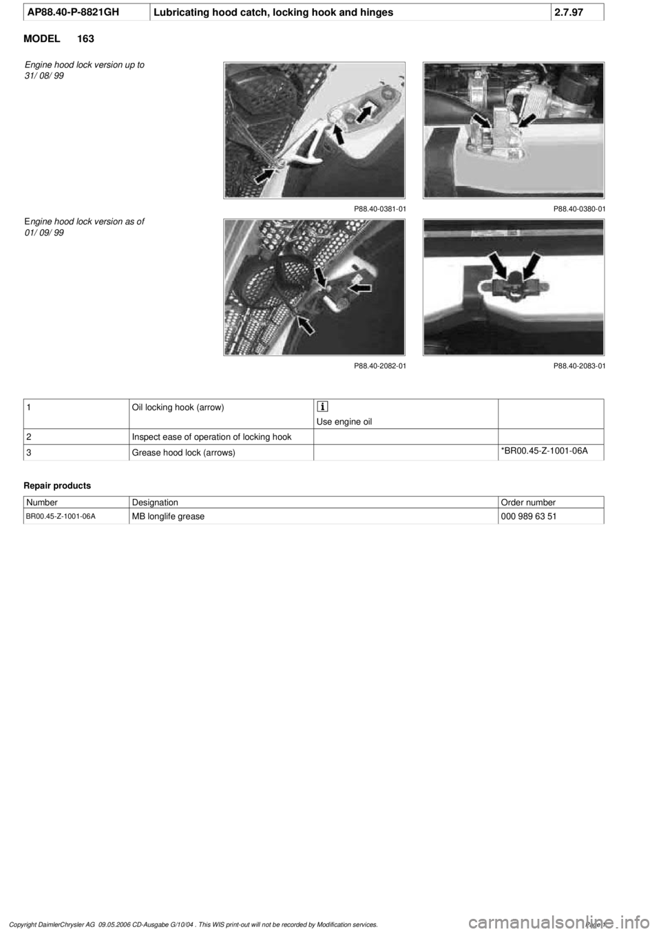
Engine hood lock version up to
31/ 08/ 99
P88.40-0381-01 P88.40-0380-01
P88.40-2082-01
E
ngine hood lock version as of
01/ 09/ 99
P88.40-2083-01
1
Oil locking hook (arrow)
Use engine oil
2
Inspect ease of operation of locking hook
3
Grease hood lock (arrows)
*BR00.45-Z-1001-06A
Repair products
Number
Designation
Order number
BR00.45-Z-1001-06A
MB longlife grease
000 989 63 51
Copyright DaimlerChrysler AG 09.05.2006 CD-Ausgabe G/10/04 . This WIS print-out will not be recorde
d by Modification services.
Page 1
Page 3210 of 4133

OS00.00-P-1001-01A
Releasing gas from gas strut and emptying
Danger!
Risk of injury
from drilling gas-filled
subassemblies or components (gas filling non-
combustible)
Wear safety glasses and face mask.
AS00.00-Z-0006-01A
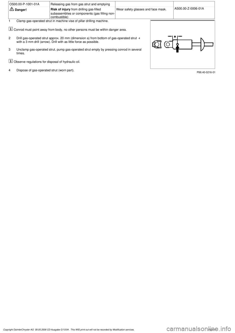
P88.40-0216-01
1
Clamp gas-operated strut in machine vise of pillar drilling machine.
Conrod must point away from body, no other persons must be within danger area.
2
Drill gas-operated strut approx. 20 mm (dimension a) from bottom of gas-operated strut
4
with a 3 mm drill (arrow). Drill with as little force as possible.
3
Unclamp gas-operated strut, pump gas-operated strut empty by pressing conrod in several
times.
Observe regulations for disposal of hydraulic oil.
4
Dispose of gas-operated strut (worn part).
Copyright DaimlerChrysler AG 09.05.2006 CD-Ausgabe G/10/04 . This WIS print-out will not be recorde
d by Modification services.
Page 1
Page 3212 of 4133

2000-01 MANUAL A/C-HEATER SYSTEMS
ML 320, ML 430 & ML 55
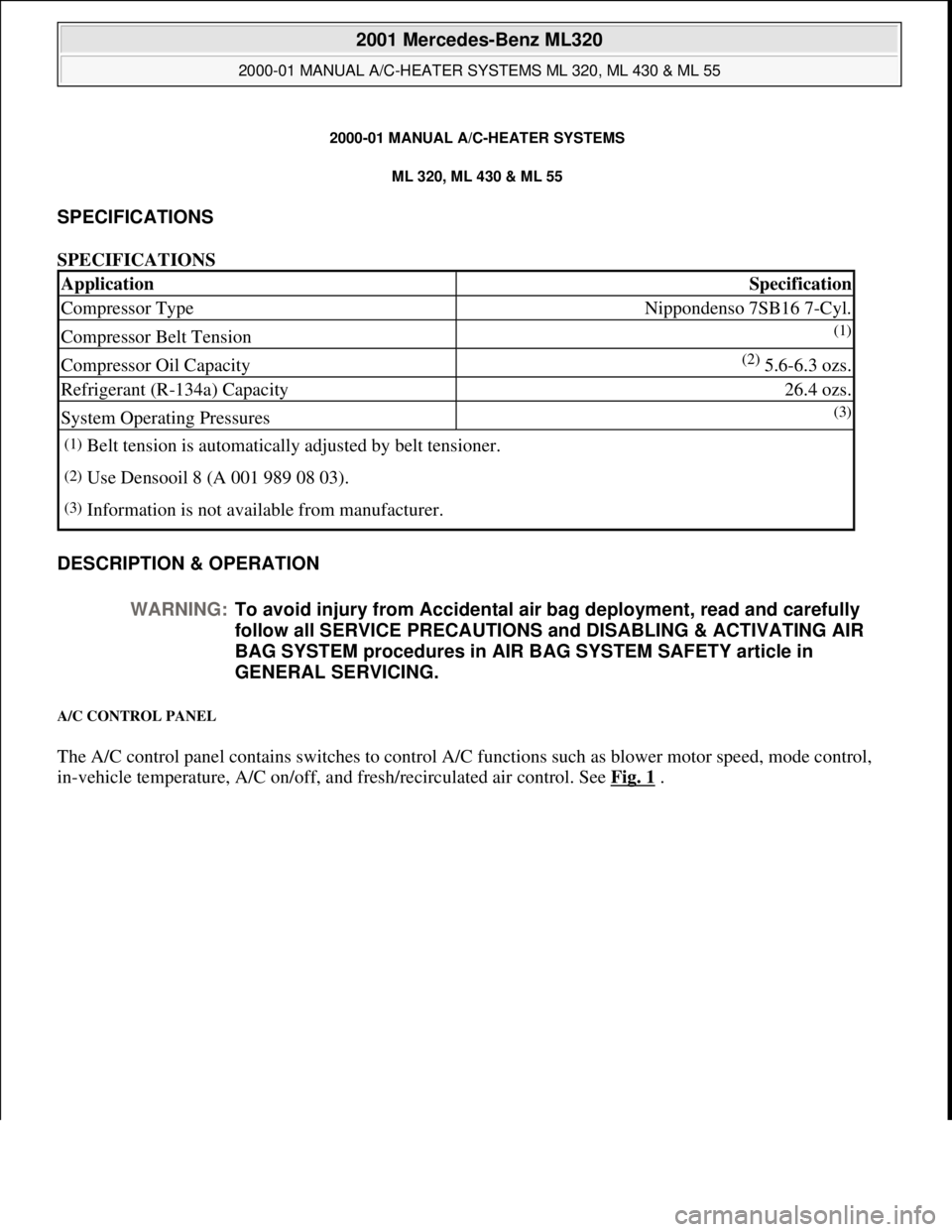
SPECIFICATIONS
SPECIFICATIONS
DESCRIPTION & OPERATION
A/C CONTROL PANEL
The A/C control panel contains switches to control A/C functions such as blower motor speed, mode control,
i
n-vehicle temperature, A/C on/off, and fresh/recirculated air control. See Fig. 1.
ApplicationSpecification
Compressor TypeNippondenso 7SB16 7-Cyl.
Compressor Belt Tension(1)
Compressor Oil Capacity(2) 5.6-6.3 ozs.
Refrigerant (R-134a) Capacity26.4 ozs.
System Operating Pressures(3)
(1)Belt tension is automatically adjusted by belt tensioner.
(2)Use Densooil 8 (A 001 989 08 03).
(3)Information is not available from manufacturer.
WARNING:To avoid injury from Accidental air bag deployment, read and carefully
follow all SERVICE PRECAUTIONS and DISABLING & ACTIVATING AIR
BAG SYSTEM procedures in AIR BAG SYSTEM SAFETY article in
GENERAL SERVICING.
2001 Mercedes-Benz ML320
2000-01 MANUAL A/C-HEATER SYSTEMS ML 320, ML 430 & ML 55
2001 Mercedes-Benz ML320
2000-01 MANUAL A/C-HEATER SYSTEMS ML 320, ML 430 & ML 55
me
Saturday, October 02, 2010 3:25:10 PMPage 1 © 2006 Mitchell Repair Information Company, LLC.
me
Saturday, October 02, 2010 3:25:13 PMPage 1 © 2006 Mitchell Repair Information Company, LLC.
Page 3228 of 4133

A/C housing. Disconnect control module connector. To install reverse removal procedure. Recode 5-digit radio
security code. Using HHT, check for DTC and erase, and set clock.
A/C PUSH BUTTON CONTROL PANEL
Removal & Installation
1. Obtain 5-digit radio security code from vehicle owner. Disconnect negative battery cable. Using radio
removal plates, remove radio. Disconnect electrical connectors.
2. Remove instrument panel center section. Remove 4 A/C control panel screws and remove control panel.
Release pull cables and disconnect connectors. To install, reverse removal procedure. Recode radio. See
RECODING RADIO
under PROGRAMMING.
BLOWER MOTOR
Removal & Installation
Remove passenger-side instrument panel under cover. Remove blower motor mounting screws from A/C
housing unit. Disconnect blower motor connector and remove blower motor. To install, reverse removal
procedure.
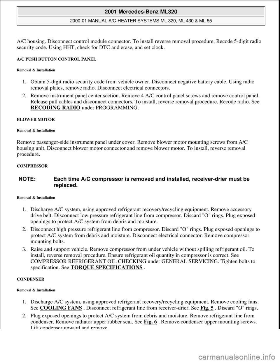
COMPRESSOR
Removal & Installation
1. Discharge A/C system, using approved refrigerant recovery/recycling equipment. Remove accessory
drive belt. Disconnect low pressure refrigerant line from compressor. Discard "O" rings. Plug exposed
openings to protect A/C system from debris and moisture.
2. Disconnect high pressure refrigerant line from compressor. Discard "O" rings. Plug exposed openings to
protect A/C system from debris and moisture. Disconnect electrical connector. Remove compressor
mounting bolts.
3. Raise and support vehicle. Remove compressor from under vehicle without spilling refrigerant oil. To
install, reverse removal procedure. Ensure refrigerant oil quantity in compressor is correct. See
COMPRESSOR REFRIGERANT OIL CHECKING under GENERAL SERVICING. Tighten bolts to
specification. See TORQUE SPECIFICATIONS
.
CONDENSER
Removal & Installation
1. Discharge A/C system, using approved refrigerant recovery/recycling equipment. Remove cooling fans.
See COOLING FANS
. Disconnect refrigerant line from receiver-drier. See Fig. 5 . Discard "O" rings.
2. Plug exposed openings to protect A/C system from debris and moisture. Remove refrigerant line from
condenser. Remove radiator upper rubber seal. See Fig. 6
. Remove condenser upper mounting screws.
Lift condenser upward and remove. NOTE: Each time A/C compressor is removed and installed, receiver-drier must be
replaced.
2001 Mercedes-Benz ML320
2000-01 MANUAL A/C-HEATER SYSTEMS ML 320, ML 430 & ML 55
me
Saturday, October 02, 2010 3:25:10 PMPage 17 © 2006 Mitchell Repair Information Company, LLC.