1997 MERCEDES-BENZ ML500 fog light
[x] Cancel search: fog lightPage 1820 of 4133
Workshop equipment
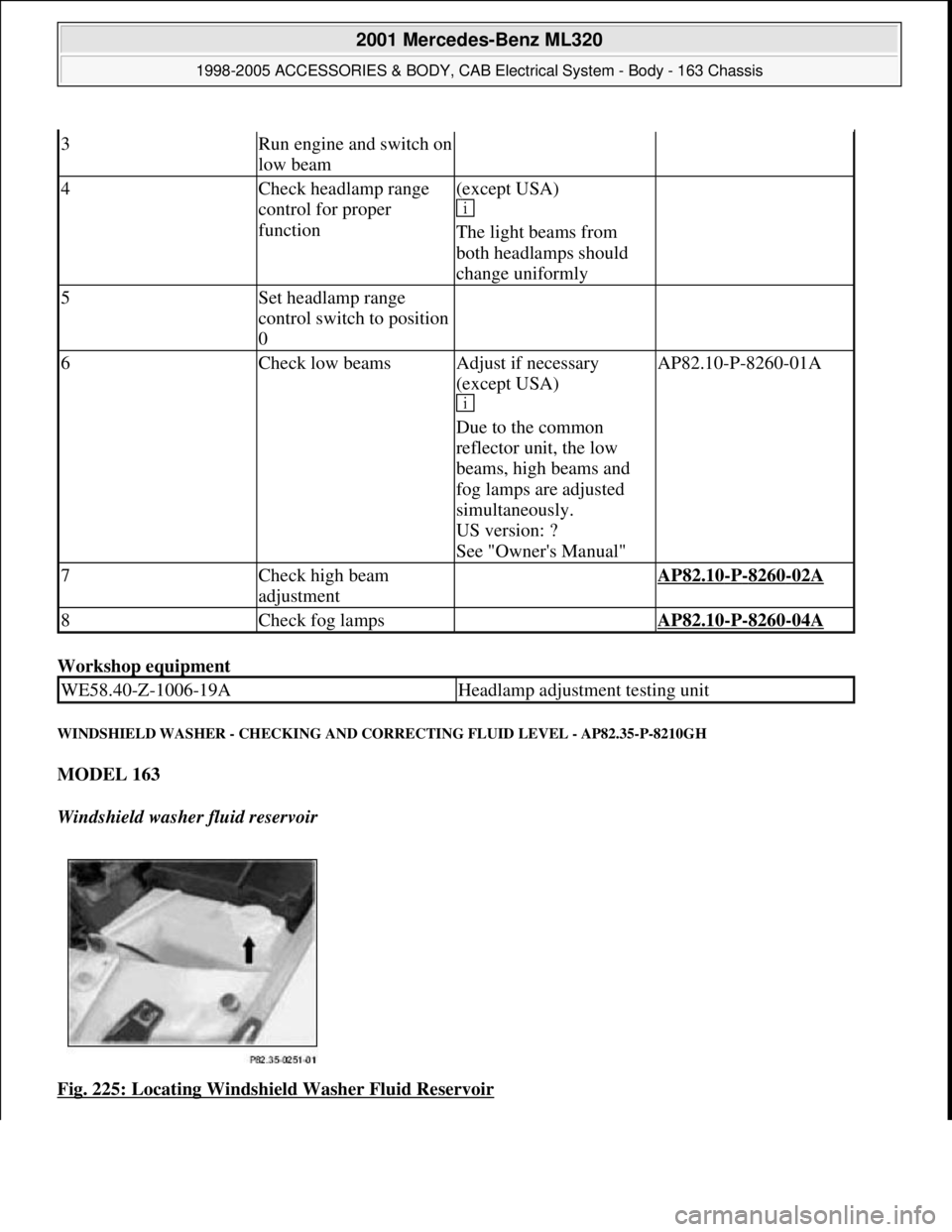
WINDSHIELD WASHER - CHECKING AND CORRECTING FLUID LEVEL - AP82.35-P-8210GH
MODEL 163
Windshield washer fluid reservoir
Fig. 225: Locating Windshield Washer Fluid Reservoir
3Run engine and switch on
low beam
4Check headlamp range
control for proper
function(except USA)
The light beams from
both headlamps should
change uniformly
5Set headlamp range
control switch to position
0
6Check low beamsAdjust if necessary
(except USA)
Due to the common
reflector unit, the low
beams, high beams and
fog lamps are adjusted
simultaneously.
US version: ?
See "Owner's Manual"AP82.10-P-8260-01A
7Check high beam
adjustment AP82.10-P-8260-02A
8Check fog lamps AP82.10-P-8260-04A
WE58.40-Z-1006-19AHeadlamp adjustment testing unit
2001 Mercedes-Benz ML320
1998-2005 ACCESSORIES & BODY, CAB Electrical System - Body - 163 Chassis
me
Saturday, October 02, 2010 3:30:10 PMPage 325 © 2006 Mitchell Repair Information Company, LLC.
Page 1968 of 4133
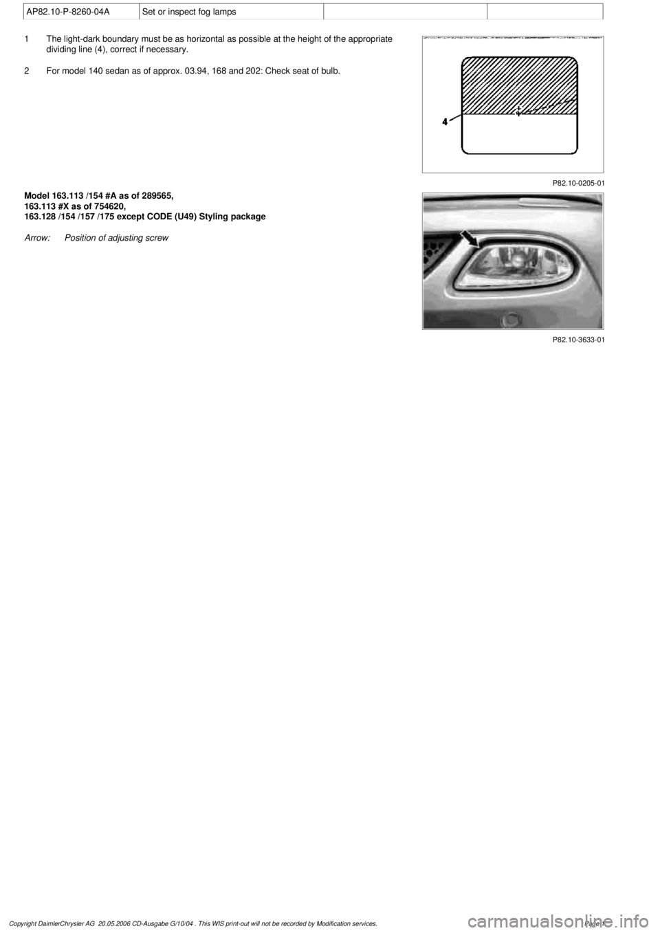
AP82.10-P-8260-04A
Set or inspect fog lamps
P82.10-0205-01
1
The light-dark boundary must be as horizontal as possible at the height of the appropriate
dividing line (4), correct if necessary.
2
For model 140 sedan as of approx. 03.94, 168 and 202: Check seat of bulb.
P82.10-3633-01
Model 163.113 /154 #A as of 289565,
163.113 #X as of 754620,
163.128 /154 /157 /175 except CODE (U49) Styling package
Arrow:
Position of adjusting screw
Copyright DaimlerChrysler AG 20.05.2006 CD-Ausgabe G/10/04 . This WIS print-out will not be recorde
d by Modification services.
Page 1
Page 1970 of 4133
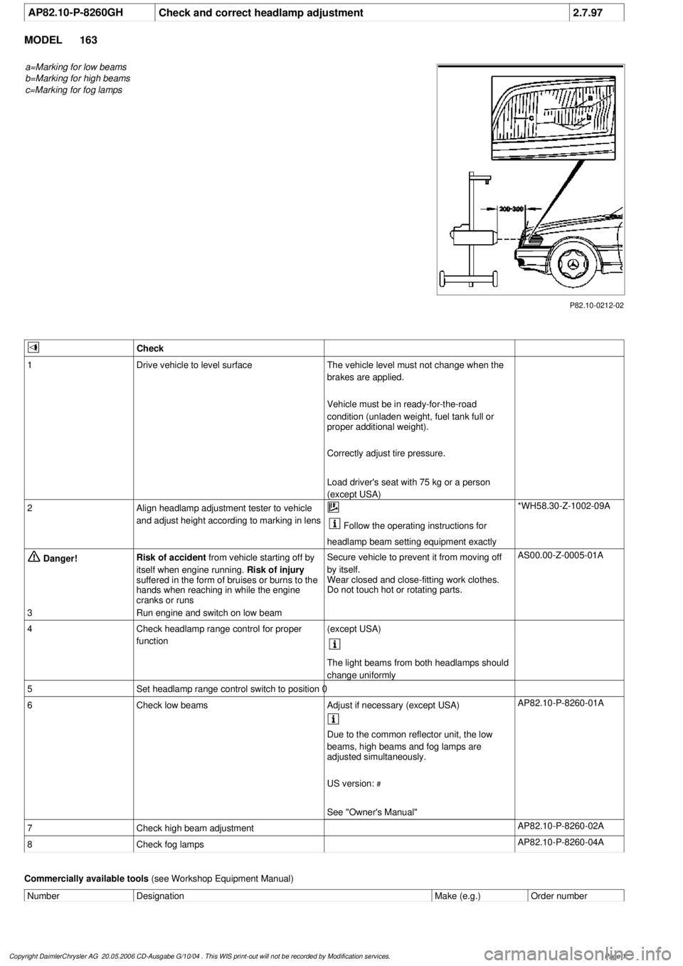
AP82.10-P-8260GH
Check and correct headlamp adjustment
2.7.97
MODEL
163
a=Marking for low beams
b=Marking for high beams
c=Marking for fog lamps
P82.10-0212-02
Check
1
Drive vehicle to level surface
The vehicle level must not change when the
brakes are applied.
Vehicle must be in ready-for-the-road
condition (unladen weight, fuel tank full or
proper additional weight).
Correctly adjust tire pressure.
Load driver's seat with 75 kg or a person
(except USA)
2
Align headlamp adjustment tester to vehicle
and adjust height according to marking in lens
Follow the operating instructions for
headlamp beam setting equipment exactly
*WH58.30-Z-1002-09A
Danger!
Risk of accident
from vehicle starting off by
itself when engine running.
Risk of injury
suffered in the form of bruises or burns to the
hands when reaching in while the engine
cranks or runs
Secure vehicle to prevent it from moving off
by itself.
Wear closed and close-fitting work clothes.
Do not touch hot or rotating parts.
AS00.00-Z-0005-01A
3
Run engine and switch on low beam
4
Check headlamp range control for proper
function
(except USA)
The light beams from both headlamps should
change uniformly
5
Set headlamp range control switch to position 0
6
Check low beams
Adjust if necessary (except USA)
AP82.10-P-8260-01A
Due to the common reflector unit, the low
beams, high beams and fog lamps are
adjusted simultaneously.
US version:
#
See "Owner's Manual"
7
Check high beam adjustment
AP82.10-P-8260-02A
8
Check fog lamps
AP82.10-P-8260-04A
Commercially available tools
(see Workshop Equipment Manual)
Number
Designation
Make (e.g.)
Order number
Copyright DaimlerChrysler AG 20.05.2006 CD-Ausgabe G/10/04 . This WIS print-out will not be recorde
d by Modification services.
Page 1
Page 2141 of 4133
2001 MERCEDES-BENZ
ML320 & ML430
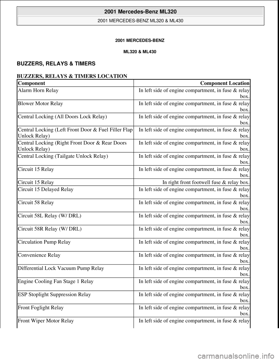
BUZZERS, RELAYS & TIMERS
BUZZERS, RELAYS & TIMERS LOCATION
ComponentComponent Location
Alarm Horn RelayIn left side of engine compartment, in fuse & relay
box.
Blower Motor RelayIn left side of engine compartment, in fuse & relay
box.
Central Locking (All Doors Lock Relay)In left side of engine compartment, in fuse & relay
box.
Central Locking (Left Front Door & Fuel Filler Flap
Unlock Relay)In left side of engine compartment, in fuse & relay
box.
Central Locking (Right Front Door & Rear Doors
Unlock Relay)In left side of engine compartment, in fuse & relay
box.
Central Locking (Tailgate Unlock Relay)In left side of engine compartment, in fuse & relay
box.
Circuit 15 RelayIn left side of engine compartment, in fuse & relay
box.
Circuit 15 RelayIn right front footwell fuse & relay box.
Circuit 15 Delayed RelayIn left side of engine compartment, in fuse & relay
box.
Circuit 58 RelayIn left side of engine compartment, in fuse & relay
box.
Circuit 58L Relay (W/ DRL)In left side of engine compartment, in fuse & relay
box.
Circuit 58R Relay (W/ DRL)In left side of engine compartment, in fuse & relay
box.
Circulation Pump RelayIn left side of engine compartment, in fuse & relay
box.
Convenience RelayIn left side of engine compartment, in fuse & relay
box.
Differential Lock Vacuum Pump RelayIn left side of engine compartment, in fuse & relay
box.
Engine Cooling Fan Stage 1 RelayIn left side of engine compartment, in fuse & relay
box.
ESP Stoplight Suppression RelayIn left side of engine compartment, in fuse & relay
box.
Front Foglight RelayIn left side of engine compartment, in fuse & relay
box.
Front Wiper Motor RelayIn left side of engine compartment, in fuse & relay
2001 Mercedes-Benz ML320
2001 MERCEDES-BENZ ML320 & ML430
2001 Mercedes-Benz ML320
2001 MERCEDES-BENZ ML320 & ML430
me
Saturday, October 02, 2010 3:21:17 PMPage 1 © 2006 Mitchell Repair Information Company, LLC.
me
Saturday, October 02, 2010 3:21:20 PMPage 1 © 2006 Mitchell Repair Information Company, LLC.
Page 2142 of 4133
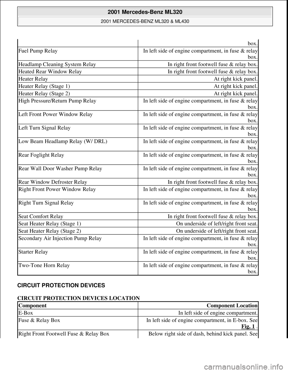
CIRCUIT PROTECTION DEVICES
CIRCUIT PROTECTION DEVICES LOCATION
box.
Fuel Pump RelayIn left side of engine compartment, in fuse & relay
box.
Headlamp Cleaning System RelayIn right front footwell fuse & relay box.
Heated Rear Window RelayIn right front footwell fuse & relay box.
Heater RelayAt right kick panel.
Heater Relay (Stage 1)At right kick panel.
Heater Relay (Stage 2)At right kick panel.
High Pressure/Return Pump RelayIn left side of engine compartment, in fuse & relay
box.
Left Front Power Window RelayIn left side of engine compartment, in fuse & relay
box.
Left Turn Signal RelayIn left side of engine compartment, in fuse & relay
box.
Low Beam Headlamp Relay (W/ DRL)In left side of engine compartment, in fuse & relay
box.
Rear Foglight RelayIn left side of engine compartment, in fuse & relay
box.
Rear Wall Door Washer Pump RelayIn left side of engine compartment, in fuse & relay
box.
Rear Window Defroster RelayIn right front footwell fuse & relay box.
Right Front Power Window RelayIn left side of engine compartment, in fuse & relay
box.
Right Turn Signal RelayIn left side of engine compartment, in fuse & relay
box.
Seat Comfort RelayIn right front footwell fuse & relay box.
Seat Heater Relay (Stage 1)On underside of left/right front seat.
Seat Heater Relay (Stage 2)On underside of left/right front seat.
Secondary Air Injection Pump RelayIn left side of engine compartment, in fuse & relay
box.
Starter RelayIn left side of engine compartment, in fuse & relay
box.
Two-Tone Horn RelayIn left side of engine compartment, in fuse & relay
box.
ComponentComponent Location
E-BoxIn left side of engine compartment.
Fuse & Relay BoxIn left side of engine compartment, in E-box. See
Fig. 1
.
Right Front Footwell Fuse & Relay BoxBelow right side of dash, behind kick panel. See
2001 Mercedes-Benz ML320
2001 MERCEDES-BENZ ML320 & ML430
me
Saturday, October 02, 2010 3:21:17 PMPage 2 © 2006 Mitchell Repair Information Company, LLC.
Page 2152 of 4133
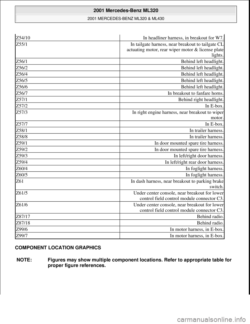
COMPONENT LOCATION GRAPHICS
Z54/10In headliner harness, in breakout for W7.
Z55/1In tailgate harness, near breakout to tailgate CL
actuating motor, rear wiper motor & license plate
lights.
Z56/1Behind left headlight.
Z56/2Behind left headlight.
Z56/4Behind left headlight.
Z56/5Behind left headlight.
Z56/6Behind left headlight.
Z56/7In breakout to fanfare horns.
Z57/1Behind right headlight.
Z57/2In E-box.
Z57/3In right engine harness, near breakout to wiper
motor.
Z57/7In E-box.
Z58/1In trailer harness.
Z58/8In trailer harness.
Z59/1In door mounted spare tire harness.
Z59/2In door mounted spare tire harness.
Z59/3In left/right door harness.
Z59/4In left/right rear door harness.
Z60/4In foglight harness.
Z60/5In foglight harness.
Z61In dash harness, near breakout to parking brake
switch.
Z61/5Under center console, near breakout for lower
control field control module connector C3.
Z61/6Under center console, near breakout for lower
control field control module connector C3.
Z87/17Behind radio.
Z87/18Behind radio.
Z99/6In motor harness, in E-box.
Z99/7In motor harness, in E-box.
NOTE: Figures may show multiple component locations. Refer to appropriate table for
proper figure references.
2001 Mercedes-Benz ML320
2001 MERCEDES-BENZ ML320 & ML430
me
Saturday, October 02, 2010 3:21:17 PMPage 12 © 2006 Mitchell Repair Information Company, LLC.
Page 2514 of 4133
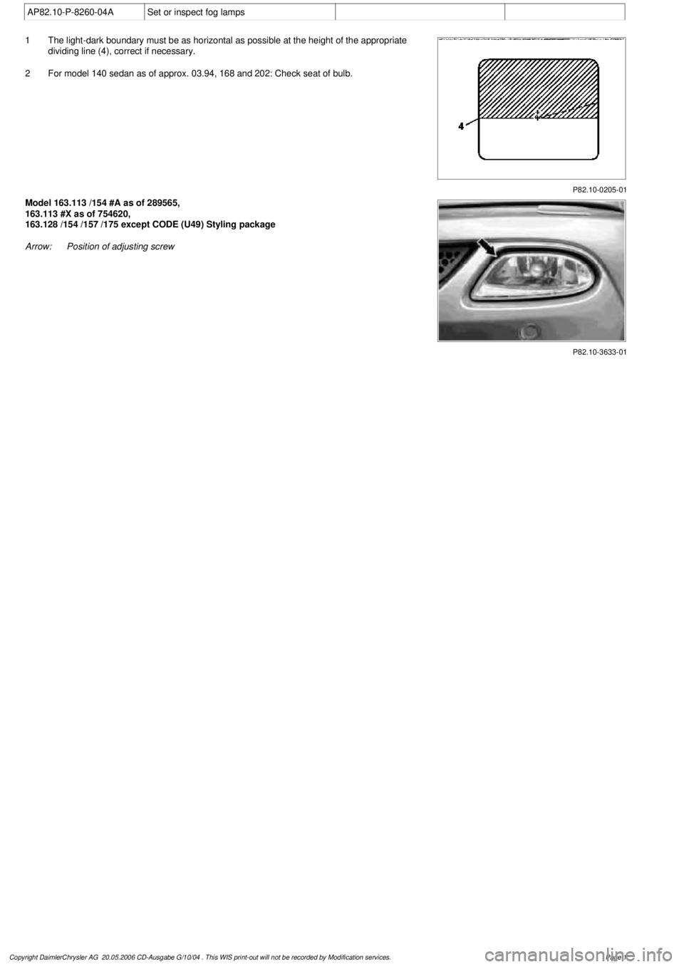
AP82.10-P-8260-04A
Set or inspect fog lamps
P82.10-0205-01
1
The light-dark boundary must be as horizontal as possible at the height of the appropriate
dividing line (4), correct if necessary.
2
For model 140 sedan as of approx. 03.94, 168 and 202: Check seat of bulb.
P82.10-3633-01
Model 163.113 /154 #A as of 289565,
163.113 #X as of 754620,
163.128 /154 /157 /175 except CODE (U49) Styling package
Arrow:
Position of adjusting screw
Copyright DaimlerChrysler AG 20.05.2006 CD-Ausgabe G/10/04 . This WIS print-out will not be recorde
d by Modification services.
Page 1
Page 3186 of 4133
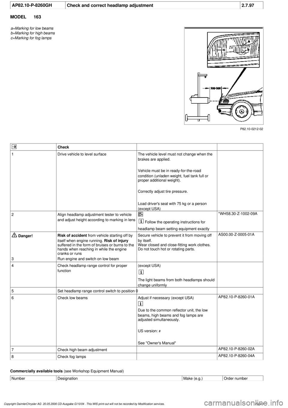
AP82.10-P-8260GH
Check and correct headlamp adjustment
2.7.97
MODEL
163
a=Marking for low beams
b=Marking for high beams
c=Marking for fog lamps
P82.10-0212-02
Check
1
Drive vehicle to level surface
The vehicle level must not change when the
brakes are applied.
Vehicle must be in ready-for-the-road
condition (unladen weight, fuel tank full or
proper additional weight).
Correctly adjust tire pressure.
Load driver's seat with 75 kg or a person
(except USA)
2
Align headlamp adjustment tester to vehicle
and adjust height according to marking in lens
Follow the operating instructions for
headlamp beam setting equipment exactly
*WH58.30-Z-1002-09A
Danger!
Risk of accident
from vehicle starting off by
itself when engine running.
Risk of injury
suffered in the form of bruises or burns to the
hands when reaching in while the engine
cranks or runs
Secure vehicle to prevent it from moving off
by itself.
Wear closed and close-fitting work clothes.
Do not touch hot or rotating parts.
AS00.00-Z-0005-01A
3
Run engine and switch on low beam
4
Check headlamp range control for proper
function
(except USA)
The light beams from both headlamps should
change uniformly
5
Set headlamp range control switch to position 0
6
Check low beams
Adjust if necessary (except USA)
AP82.10-P-8260-01A
Due to the common reflector unit, the low
beams, high beams and fog lamps are
adjusted simultaneously.
US version:
#
See "Owner's Manual"
7
Check high beam adjustment
AP82.10-P-8260-02A
8
Check fog lamps
AP82.10-P-8260-04A
Commercially available tools
(see Workshop Equipment Manual)
Number
Designation
Make (e.g.)
Order number
Copyright DaimlerChrysler AG 20.05.2006 CD-Ausgabe G/10/04 . This WIS print-out will not be recorde
d by Modification services.
Page 1