1997 MERCEDES-BENZ ML500 brakes
[x] Cancel search: brakesPage 1123 of 4133

319 Index
Rear passenger compartment 141
Rear window defroster 133
Residual heat utilization 140
Residual ventilation 140
Switching off 137
Switching on 137
Automatic headlamp mode 108
Automatic interior lighting control
Activating 113
Deactivating 113
Automatic locking when driving 93
Automatic transmission 119
Accelerator position 123
Emergency operation (Limp Home
Mode) 124
Gear ranges 121
Gear selector lever position 122
Gear shifting malfunctions 124
Kickdown 123
Manual shifting 120
One-touch gearshifting 120Selector lever position 119
Towing a trailer 124
Transmission fluid 222
B
BabySmart
TM
Airbag deactivation system 70
Compatible child seats 70, 311
Self-test 70
BabySmart
TM airbag deactivation
system 311
Backrest tilt 35
Backup lamps 267, 270
Bulbs 267
BAS 78, 311
Malfunction indicator lamp 245, 246,
247
Warning lamp 245, 246, 247
Batteries, remote control
Changing 262
Batteries, vehicle 223
Battery discharged
Jump starting 281Battery indicator lamp
Indicator lamp 254
Battery, vehicle 223, 278
Charging 279
Disconnecting 279
Reconnecting 279
Reinstalling 279
Removing 279
Bi-Xenon headlamps* 311
Blocking
Rear door window operation 73
Brake assist system (BAS) 311
Brake fluid 302
Brake lamp bulbs 267
Brake lamp, high mounted 267
Brake pad wear
Indicator lamp 254
Brakes 194
Warning lamp 244
Break-in period 192
Page 1132 of 4133

328 IndexK
Key
Global locking 89
Global unlocking 89
Loss of 90
Positions in steering lock 33
Remote control with folding key 88
Unlocking liftgate 89
Unlocking the driver’s door, fuel filler
flap 89
Key positions in steering lock 33
Key, Mechanical 261
Key, Remote control
Unlocking with 32
Kickdown 123, 313
L
Labels, identification 292
Lamp bulbs, exterior 266
Lamps, exterior
Front 266
Rear 267Lamps, indicator and warning
4-ETS 251, 252
ABS 242
Adjustable steering column 253
AIRBAG OFF 63, 243
BAS 78, 245, 246, 247
Battery indicator lamp 254
Brake pad wear 254
Brakes 244
CHECK ENGINE 248
Coolant 249
EBP 245
Engine diagnostics 248
ESP 245, 246, 247, 251
Front fog lamps 253
Fuel reserve 252
Low engine oil level 253
LOW RANGE 252
Low washer system fluid level 253
Seat belts 253
Service indicator 232
SRS 255
Turn signals 25LATCH child seat anchors 72
LATCH child seat mounts 72
Layout of poly-V-belt drive 293
Leather upholstery
Cleaning 239
Lever
For cruise control 150
License plate lamps
Replacing bulbs 267, 271
Liftgate
Closing 92
Opening 89, 91
Opening from inside 91
Opening from outside 91
Light alloy wheels
Cleaning 238
Lighter
Rear center console 169
Lighter see cigarette lighter 168
Page 1252 of 4133
Courtesy of MERCEDES-BENZ OF NORTH AMERICA.
Multiple-Disc Brake, Location
Three multiple-disc brakes arranged as the front, center and rear multiple-disc brake (B1, B3, B2) are
located in the planetary gear sets in the transmission housing. See Fig. 43
.
Multiple-Disc Brake, Task
Brace the ring gear, sun gear or planet carrier of a planetary gear set against the transmission housing in
order to transmit the drive torque.
Multiple-Disc Brake, Design
A multiple-disc brake consists of a number of internally toothed discs (10) on an internally toothed disc
carrier and externally toothed discs (9) on an externally toothed disc carrier, which is rigidly connected to
the transmission housing.
Multiple-Disc Brake, Function
See MULTIPLE
-DISC BRAKE, FUNCTION.
Multiple-Disc Brake, Function
2001 Mercedes-Benz ML320
1998-03 AUTOMATIC TRANSMISSIONS Complete Transmissions - ML 320 - 722.662
me
Saturday, October 02, 2010 3:15:26 PMPage 83 © 2006 Mitchell Repair Information Company, LLC.
Page 1352 of 4133
Fig. 106: Torque Converter Lockup Clutch, Function
Courtesy of MERCEDES-BENZ OF NORTH AMERICA.
Operation
When actuated by the ETC control module (N15/3), oil pressure controlled by the torque converter lockup
PWM solenoid Valve (Y3/6y6) is directed through the input shaft (1) to the pressure chamber behind the piston
(16d). See Fig. 106
. The piston presses the clutch pack (16c) together and allows torque to be transferred
directly between the impeller (P) and turbine wheel (T). The torque converter lockup clutch is activated in 5th,
4th and 3rd gears in relation to the engine speed and engine load.
AUTOMATIC TRANSMISSION, FUNCTION
Transmission without touch shift. 722.6 in MODEL 163, 170, 202, 208, 210.
Transmission 722.6 in MODEL 129, 140.
Automatic transmission 722.6 is an electronically controlled 5-speed transmission with a lockup clutch in the
torque converter.
The ratios for the gear stages are achieved by three planetary gear sets. The 5th gear is designed with a step-up
ratio as an overdrive.
Shifting is initiated electronically. The gears are shifted by the corresponding combination of three
hydraulically actuated multi-plate brakes, three hydraulically actuated multi-disc clutches and two mechanical
freewheels.
Basically automatic transmission 722.6 with electronic control offers the following advantages:
Reduced fuel consumption
Improved shift comfort
More favorable gear steps as a result of 5 gears
Enhanced life and reliability
Reduced servicing costs
The electrohydraulic control unit is bolted onto the bottom of the transmission housing. The end of the
transmission is formed by an oil pan made of sheet steel.
The oil pressure for the converter lockup clutch and center multiple disc clutch is supplied via holes in the input
shaft. The oil pressure to the rear multiple-disc clutch is routed through the output shaft. The lubricating oil is
supplied and distributed by additional bore holes in both shafts. All bearing points of the gear sets as well as
freewheels and shift elements are supplied with lubricating oil.
The parking lock gear and drive flange are connected to the output shaft by gearing.
Freewheels F1 and F2 optimize shiftin
g. The front freewheel (F1) rests against the stator shaft extension on the
2001 Mercedes-Benz ML320
1998-03 AUTOMATIC TRANSMISSIONS Complete Transmissions - ML 320 - 722.662
me
Saturday, October 02, 2010 3:15:28 PMPage 183 © 2006 Mitchell Repair Information Company, LLC.
Page 1358 of 4133
Fig. 108: Selector Lever Positions
Courtesy of MERCEDES-BENZ OF NORTH AMERICA.
AUTOMATIC TRANSMISSION, FUNCTION
Transmission With Touch Shift 722.6 In Model 163
Transmission 722.6 is an electronically controlled 5-speed transmission with a lockup clutch in the torque
converter.
The ratios for the gear stages are achieved by 3 planetary gearsets. The 5th gear is designed as a low-rev gear
with an overdrive ratio.
Shifting is initiated electronically. The gears are shifted by the corresponding combination of 3 hydraulically
actuated multi-disk brakes, 3 hydraulically actuated multi-disk clutches and 2 mechanical freewheels.
The oil pump as well as the external plate carrier of the front multi-disk brake are bolted to the torque converter
housing.
The mechanical part of the transmission 722.6 consists of a drive shaft, output shaft, a sun gear shaft and 3
planetary sets which are coupled to each other.
The electrohydraulic control unit is screwed onto the transmission housing from below. The end of the
transmission if formed by an oil pan made of sheet steel.
The oil pressure of the torque converter lockup clutch and center multi-disk clutch is supplied via bore holes in
the drive shaft. The oil pressure to the rear multi-disk clutch is supplied via the output shaft. The lubricating oil
is supplied and distributed by additional bore holes in both shafts. Oil is supplied to all bearing points of the
gearsets as well as to the freewheels and shifting elements.
The parking lock gear and drive flange are connected to the output shaft by gearing.
Basically transmission 722.6 with electronic control offers the following advantages:
Reduced fuel consumption.
Greater ease of shifting.
Favorable spacing by 5 gears.
Long service life and high reliability.
Low maintenance costs.
The torque converter housing and transmission housing consist of a light-metal alloy. Both housings are bolted
together and are centered via the external plate carrier of the multi-disk brake at the front. A coated intermediate
panel seals the two components.
Freewheels F1 and F2 optimize shifting. The front freewheel F1 is supported on the extension of the stator shaft
on the transmission end and connects in the lockin
g direction the sun gear of the front planetary gearset with the
2001 Mercedes-Benz ML320
1998-03 AUTOMATIC TRANSMISSIONS Complete Transmissions - ML 320 - 722.662
me
Saturday, October 02, 2010 3:15:28 PMPage 189 © 2006 Mitchell Repair Information Company, LLC.
Page 1370 of 4133
Operation
The term power transmission refers to the transmission of propulsion power and engine torques. Via the
mechanical/hydraulic connection between the engine, torque converter and the downstream automatic
transmission the engine torques are transmitted to the driving wheels and are converted in the transmission via
several planetary gear sets.
Power is transferred in the torque converter via the driven impeller by diverting hydraulic fluid to the turbine
wheel, which is connected to the input shaft. See Fig. 117
.
When the torque converter lockup clutch is engaged, power is transmitted via this mechanical connection. Via
the gear wheels of the individual planetary gear sets the torques coming from the converter are passed on to the
output shaft with the aid of freewheels, multi-disk clutches and brakes, depending on the ratio and shift element
operated.
A reduction of the output speed in the low gears provides lower vehicle speeds with high tractive forces and
drive torques at the drive wheels.
Power Flow In 1st Gear, Function
See POWER FLOW IN 1ST GEAR, FUNCTION
.
Power Flow In 2nd Gear, Function
See POWER FLOW IN 2ND GEAR FUNCTION
.
Power Flow In 3rd Gear, Function
See POWER FLOW IN 3RD GEAR FUNCTION
.
Power Flow In 4th Gear, Function
See POWER FLOW IN 4TH GEAR FUNCTION
.
Power Flow In 5th Gear, Function
See POWER FLOW IN 5TH GEAR FUNCTION
.
Power Flow In Reverse, Function
See POWER FLOW IN REVERSE, FUNCTION
.
Function Of Torque Converter Lock-Up Clutch Control
See FUNCTION OF TORQUE CONVERTER LOCKUP CLUTCH CONTROL
.
Power Flow In 1st Gear, Function
2001 Mercedes-Benz ML320
1998-03 AUTOMATIC TRANSMISSIONS Complete Transmissions - ML 320 - 722.662
me
Saturday, October 02, 2010 3:15:28 PMPage 201 © 2006 Mitchell Repair Information Company, LLC.
Page 1541 of 4133
WIPER, FUNCTION - GF82.30-P-3004GH
MODEL 163
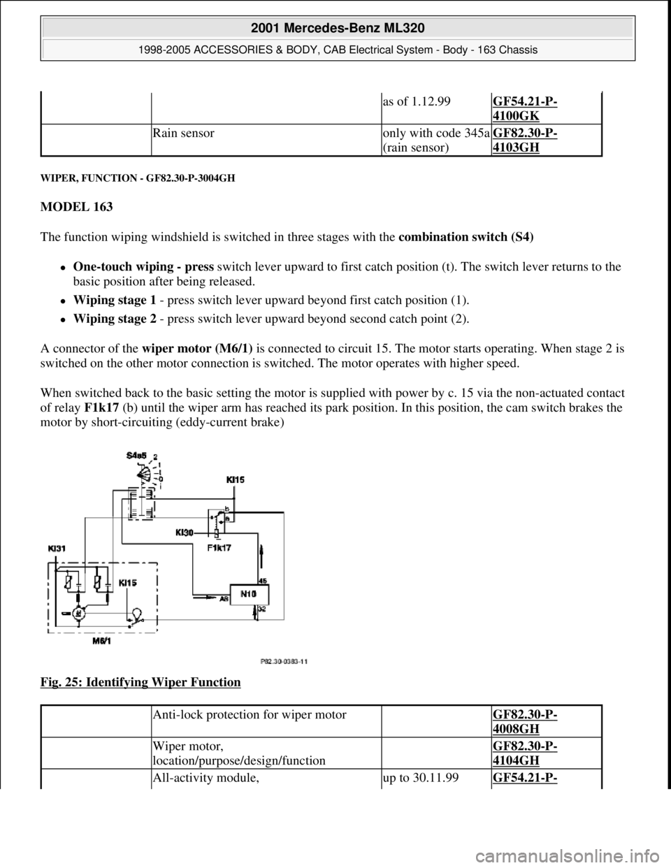
The function wiping windshield is switched in three stages with the combination switch (S4)
One-touch wiping - press switch lever upward to first catch position (t). The switch lever returns to the
basic position after being released.
Wiping stage 1 - press switch lever upward beyond first catch position (1).
Wiping stage 2 - press switch lever upward beyond second catch point (2).
A connector of the wiper motor (M6/1) is connected to circuit 15. The motor starts operating. When stage 2 is
switched on the other motor connection is switched. The motor operates with higher speed.
When switched back to the basic setting the motor is supplied with power by c. 15 via the non-actuated contact
of relay F1k17 (b) until the wiper arm has reached its park position. In this position, the cam switch brakes the
motor by short-circuiting (eddy-current brake)
Fig. 25: Identifying Wiper Function
as of 1.12.99GF54.21-P-
4100GK
Rain sensoronly with code 345a
(rain sensor)GF82.30-P-
4103GH
Anti-lock protection for wiper motor GF82.30-P-
4008GH
Wiper motor,
location/purpose/design/function GF82.30-P-
4104GH
All-activity module, up to 30.11.99GF54.21-P-
2001 Mercedes-Benz ML320
1998-2005 ACCESSORIES & BODY, CAB Electrical System - Body - 163 Chassis
me
Saturday, October 02, 2010 3:30:04 PMPage 46 © 2006 Mitchell Repair Information Company, LLC.
Page 1819 of 4133
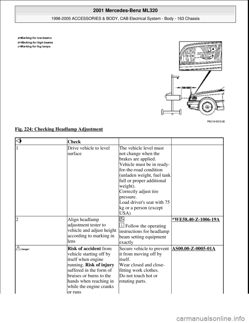
Fig. 224: Checking Headlamp Adjustment
Check
1Drive vehicle to level
surfaceThe vehicle level must
not change when the
brakes are applied.
Vehicle must be in ready-
for-the-road condition
(unladen weight, fuel tank
full or proper additional
weight).
Correctly adjust tire
pressure.
Load driver's seat with 75
kg or a person (except
USA)
2Align headlamp
adjustment tester to
vehicle and adjust height
according to marking in
lens
Follow the operating
instructions for headlamp
beam setting equipment
exactly*WE58.40-Z-1006-19A
Risk of accident from
vehicle starting off by
itself when engine
running. Risk of injury
suffered in the form of
bruises or burns to the
hands when reaching in
while the engine cranks
or runsSecure vehicle to prevent
it from moving off by
itself.
Wear closed and close-
fitting work clothes.
Do not touch hot or
rotating parts.AS00.00-Z-0005-01A
2001 Mercedes-Benz ML320
1998-2005 ACCESSORIES & BODY, CAB Electrical System - Body - 163 Chassis
me
Saturday, October 02, 2010 3:30:10 PMPage 324 © 2006 Mitchell Repair Information Company, LLC.