1997 MERCEDES-BENZ ML430 AUX
[x] Cancel search: AUXPage 3194 of 4133
15
Adjust gap dimensions
Gap dimensions
*BE60.00-P-1001-01D
Feeler gage
*129589032100
16
Align engine hood catch upper section (5)
centered in longitudinal and transverse
direction to engine hood catch lower section
and tighten
*BA88.40-P-1004-01C
17
Ensure that engine hood catch catches
properly
For this purpose, close engine hood and
pull upward with a jerk.
18
Release engine hood and ensure that safety
hook catches on radiator crossmember
19
Close engine hood (2)
Test and adjustment values, gap dimensions at hoods, doors and covers
Number
Designation
Model 163
BE60.00-P-1001-01D
Gap
dimension
Engine hood to fender
Dimension "A"
mm
5.0 (
F
0.5)
Engine hood to headlamp
Dimension "R"
mm
5.0 (
F
0.5)
Engine hood to radiator grille
Dimension "O"
mm
5.0 (
F
0.5)
Radiator grill to headlamp
Dimension "N"
mm
-
Fig., see
AR60.00-P-0700-
01GH
Engine hood
Number
Designation
Model 163
BA88.40-P-1001-01C
Bolt, engine hood hinge on engine hood
Nm
10
BA88.40-P-1002-01C
Nut, engine hood hinge to body
Nm
18
BA88.40-P-1004-01C
Bolt, engine hood catch upper section to engine
hood
Nm
12
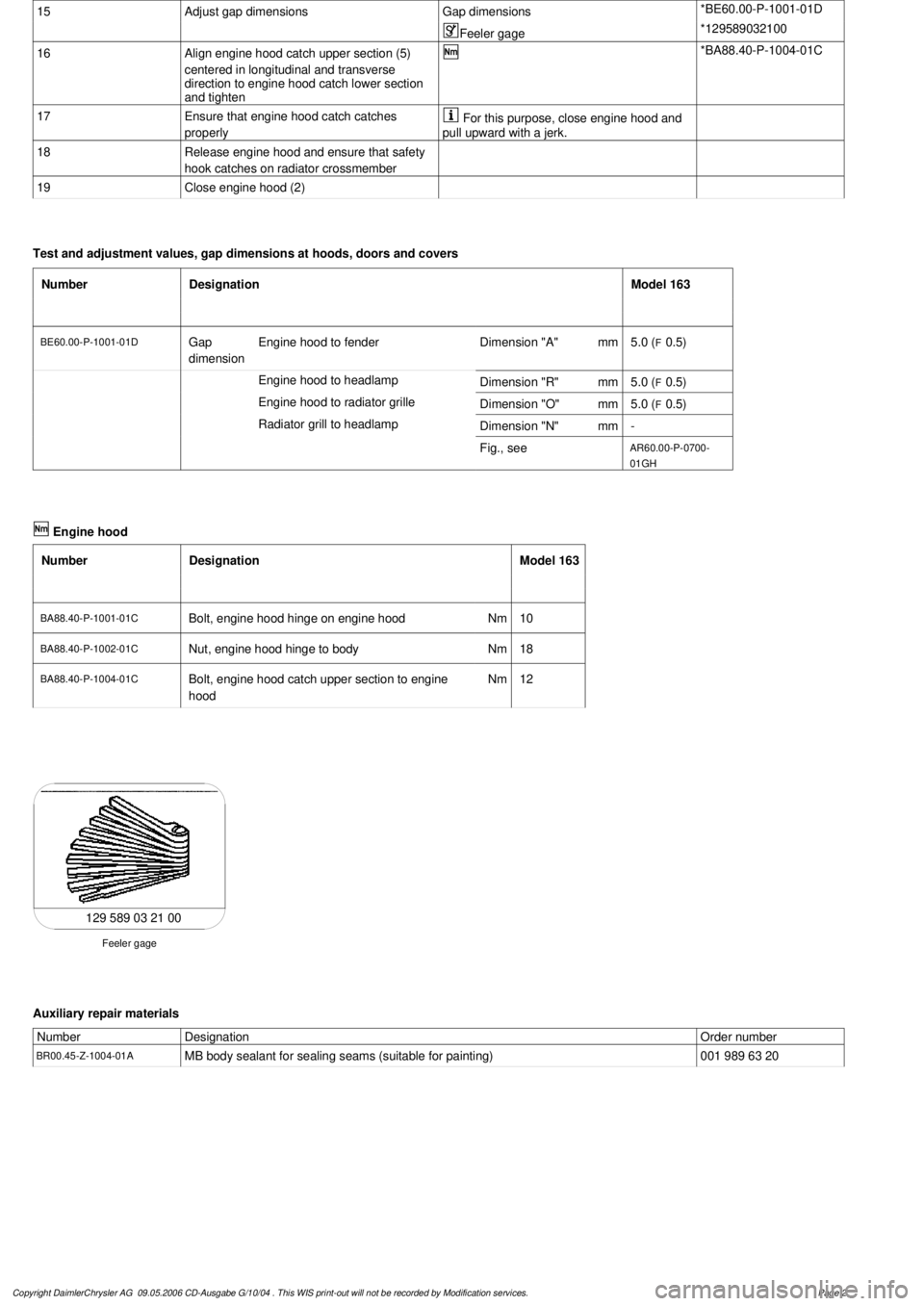
129 589 03 21 00
Feeler gage
Auxiliary repair materials
Number
Designation
Order number
BR00.45-Z-1004-01A
MB body sealant for sealing seams (suitable for painting)
001 989 63 20
Copyright DaimlerChrysler AG 09.05.2006 CD-Ausgabe G/10/04 . This WIS print-out will not be recorde
d by Modification services.
Page 2
Page 3196 of 4133
15
Adjust gap dimensions
Gap dimensions
*BE60.00-P-1001-01D
Feeler gage
*129589032100
16
Align engine hood catch upper section (5)
centered in longitudinal and transverse
direction to engine hood catch lower section
and tighten
*BA88.40-P-1004-01C
17
Ensure that engine hood catch catches
properly
For this purpose, close engine hood and
pull upward with a jerk.
18
Release engine hood and ensure that safety
hook catches on radiator crossmember
19
Close engine hood (2)
Test and adjustment values, gap dimensions at hoods, doors and covers
Number
Designation
Model 163
BE60.00-P-1001-01D
Gap
dimension
Engine hood to fender
Dimension "A"
mm
5.0 (
F
0.5)
Engine hood to headlamp
Dimension "R"
mm
5.0 (
F
0.5)
Engine hood to radiator grille
Dimension "O"
mm
5.0 (
F
0.5)
Radiator grill to headlamp
Dimension "N"
mm
-
Fig., see
AR60.00-P-0700-
01GH
Engine hood
Number
Designation
Model 163
BA88.40-P-1001-01C
Bolt, engine hood hinge on engine hood
Nm
10
BA88.40-P-1002-01C
Nut, engine hood hinge to body
Nm
18
BA88.40-P-1004-01C
Bolt, engine hood catch upper section to engine
hood
Nm
12
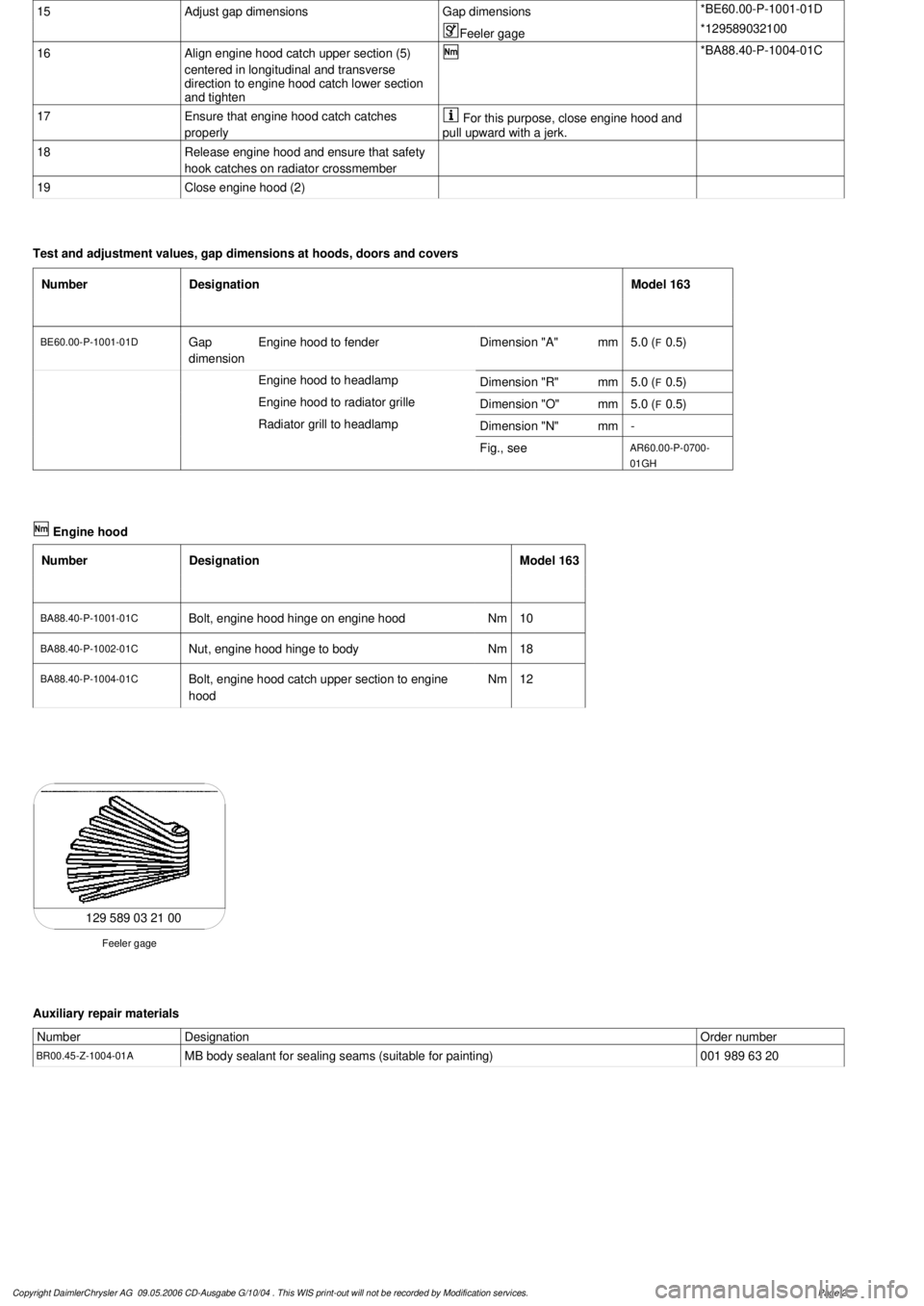
129 589 03 21 00
Feeler gage
Auxiliary repair materials
Number
Designation
Order number
BR00.45-Z-1004-01A
MB body sealant for sealing seams (suitable for painting)
001 989 63 20
Copyright DaimlerChrysler AG 09.05.2006 CD-Ausgabe G/10/04 . This WIS print-out will not be recorde
d by Modification services.
Page 2
Page 3225 of 4133
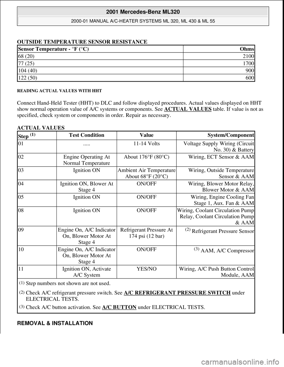
OUTSIDE TEMPERATURE SENSOR RESISTANCE
READING ACTUAL VALUES WITH HHT
Connect Hand-Held Tester (HHT) to DLC and follow displayed procedures. Actual values displayed on HHT
show normal operation value of A/C systems or components. See ACTUAL VALUES
table. If value is not as
specified, check system or components in order. Repair as necessary.
ACTUAL VALUES
REMOVAL & INSTALLATION
Sensor Temperature - °F (°C)Ohms
68 (20)2100
77 (25)1700
104 (40)900
122 (50)600
Step (1) Test ConditionValueSystem/Component
01.....11-14 VoltsVoltage Supply Wiring (Circuit
No. 30) & Battery
02Engine Operating At
Normal TemperatureAbout 176°F (80°C)Wiring, ECT Sensor & AAM
03Ignition ONAmbient Air Temperature
About 68°F (20°C)Wiring, Outside Temperature
Sensor & AAM
04Ignition ON, Blower At
Stage 4ON/OFFWiring, Blower Motor Relay,
Blower Motor & AAM
05Ignition ONON/OFFWiring, Engine Cooling Fan
Stage 1, Aux. Fan & AAM
08Ignition ONON/OFFWiring, Coolant Circulation Pump
Relay, Coolant Circulation Pump
& AAM
09Engine On, A/C Indicator
On, Blower Motor At
Stage 4Refrigerant Pressure At
174 psi (12 bar)(2) Refrigerant Pressure Sensor
10Engine On, A/C Indicator
On, Blower Motor At
Stage 4ON/OFF(3) AAM, A/C Compressor
11Ignition ON, Activate
A/C SystemYES/NOWiring, A/C Push Button Control
Module, AAM
(1)Step numbers not shown are not used.
(2)Check A/C refrigerant pressure switch. See A/C REFRIGERANT PRESSURE SWITCH under
ELECTRICAL TESTS.
(3)Check A/C button activation. See A/C BUTTON under ELECTRICAL TESTS.
2001 Mercedes-Benz ML320
2000-01 MANUAL A/C-HEATER SYSTEMS ML 320, ML 430 & ML 55
me
Saturday, October 02, 2010 3:25:10 PMPage 14 © 2006 Mitchell Repair Information Company, LLC.
Page 3318 of 4133
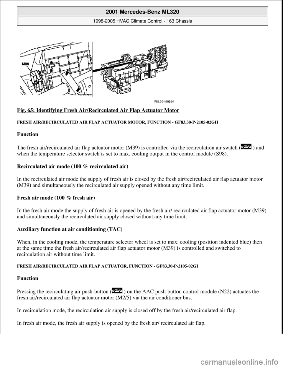
Fig. 65: Identifying Fresh Air/Recirc ulated Air Flap Actuator Motor
FRESH AIR/RECIRCULATED AIR FLAP ACTUATOR MOTO R, FUNCTION - GF83.30-P-2105-02GH
Function
The fresh air/recirculated air flap actuator motor (M39) is controlled via the recirculation air switch ( ) and
when the temperature selector switch is set to max. cooling output in the control module (S98).
Recirculated air mode (100 % recirculated air)
In the recirculated air mode the supply of fresh air is closed by the fresh air/recirculated air flap actuator motor
(M39) and simultaneously the recirculated air supply opened without any time limit.
Fresh air mode (100 % fresh air)
In the fresh air mode the supply of fresh air is opened by th e fresh air/ recirculated air flap actuator motor (M39)
and simultaneously the recirculated air supply closed without any time limit.
Auxiliary function at air conditioning (TAC)
When, in the cooling mode, the temperat ure selector wheel is set to max. cooling (position indented blue) then
at the same time the fres h air/recirculated air flap actuator moto r (M39) is controlled and switched to
recirculation air wi thout time limit.
FRESH AIR/RECIRCUL ATED AIR FLAP ACTUATOR, FU NCTION - GF83.30-P-2105-02GI
Function
Pressing the recirculating air push- button ( ) on the AAC push-button control module (N22) actuates the
fresh air/recirculated air flap actuator motor (M2/5) via the air conditioner bus.
In recirculation mode, the recircul ation air supply is closed off by th e fresh air/recirculated air flap.
In fresh air mode, the fresh air supply is ope ned by the fresh air/ recirculated air flap.
2001 Mercedes-Benz ML320
1998-2005 HVAC Climate Control - 163 Chassis
me
Saturday, October 02, 2010 3:23:15 PMPage 74 © 2006 Mitchell Repair Information Company, LLC.
Page 3323 of 4133
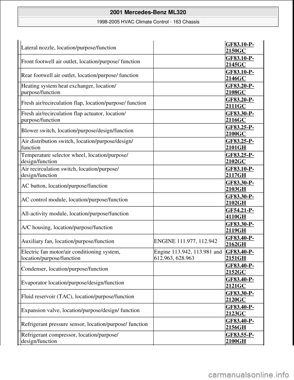
Lateral nozzle, location/purpose/function GF83.10-P-
2150GC
Front footwell air outlet, location/purpose/ function GF83.10-P-
2145GC
Rear footwell air outlet, location/purpose/ function GF83.10-P-
2146GC
Heating system heat exchanger, location/
purpose/function GF83.20-P-
2108GC
Fresh air/recirculation flap, location/purpose/ function GF83.20-P-
2111GC
Fresh air/recirculation flap actuator, location/
purpose/function GF83.30-P-
2116GC
Blower switch, location/purpose/design/function GF83.25-P-
2100GC
Air distribution switch, location/purpose/design/
function GF83.25-P-
2101GH
Temperature selector wheel, location/purpose/
design/function GF83.25-P-
2102GC
Air recirculation switch, location/purpose/
design/function GF83.10-P-
2117GH
AC button, location/purpose/function GF83.30-P-
2103GH
AC control module, location/purpose/function GF83.30-P-
2102GH
All-activity module, location/purpose/function GF54.21-P-
4110GH
A/C housing, location/purpose/function GF83.30-P-
2119GH
Auxiliary fan, location/purpose/functionENGINE 111.977, 112.942GF83.40-P-
2162GH
Electric fan motor/air conditioning system,
location/purpose/functionEngine 113.942, 113.981 and
612.963, 628.963GF83.40-P-
2151GH
Condenser, location/purpose/function GF83.40-P-
2152GC
Evaporator location/purpose/design/function GF83.40-P-
2121GC
Fluid reservoir (TAC), location/purpose/function GF83.30-P-
2120GC
Expansion valve, location/purpose/design/ function GF83.40-P-
2123GC
Refrigerant pressure sensor, location/purpose/ function GF83.40-P-
2156GH
Refrigerant compressor, location/purpose/
design/function GF83.55-P-
2100GH
2001 Mercedes-Benz ML320
1998-2005 HVAC Climate Control - 163 Chassis
me
Saturday, October 02, 2010 3:23:15 PMPage 79 © 2006 Mitchell Repair Information Company, LLC.
Page 3328 of 4133
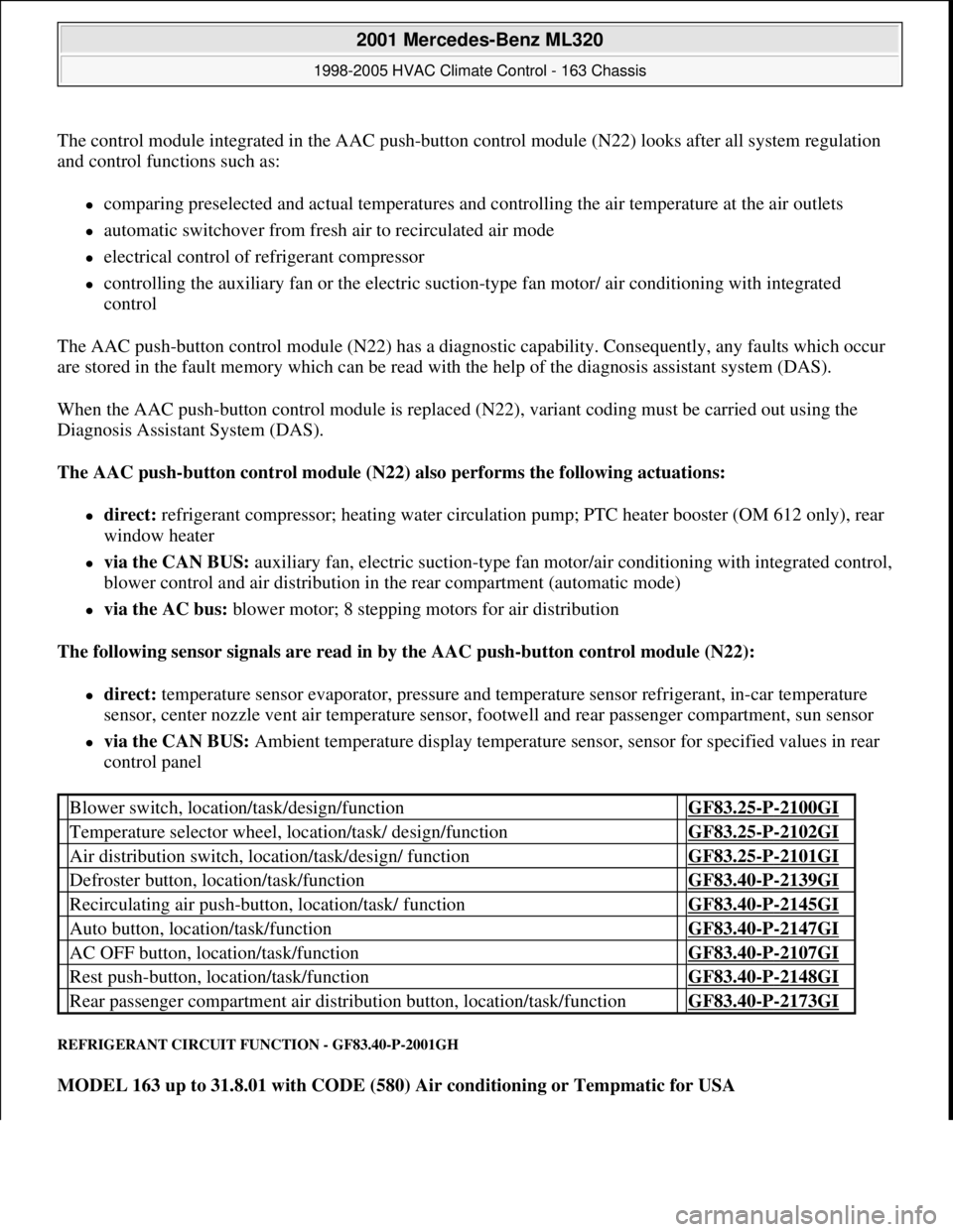
The control module integrated in the AAC push-button control module (N22) looks after all system regulation
and control functions such as:
comparing preselected and actual temperatures and controlling the air temperature at the air outlets
automatic switchover from fresh air to recirculated air mode
electrical control of refrigerant compressor
controlling the auxiliary fan or the electric suction-type fan motor/ air conditioning with integrated
control
The AAC push-button control module (N22) has a diagnostic capability. Consequently, any faults which occur
are stored in the fault memory which can be read with the help of the diagnosis assistant system (DAS).
When the AAC push-button control module is replaced (N22), variant coding must be carried out using the
Diagnosis Assistant System (DAS).
The AAC push-button control module (N22) also performs the following actuations:
direct: refrigerant compressor; heating water circulation pump; PTC heater booster (OM 612 only), rear
window heater
via the CAN BUS: auxiliary fan, electric suction-type fan motor/air conditioning with integrated control,
blower control and air distribution in the rear compartment (automatic mode)
via the AC bus: blower motor; 8 stepping motors for air distribution
The following sensor signals are read in by the AAC push-button control module (N22):
direct: temperature sensor evaporator, pressure and temperature sensor refrigerant, in-car temperature
sensor, center nozzle vent air temperature sensor, footwell and rear passenger compartment, sun sensor
via the CAN BUS: Ambient temperature display temperature sensor, sensor for specified values in rear
control panel
REFRIGERANT CIRCUIT FUNCTION - GF83.40-P-2001GH
MODEL 163 up to 31.8.01 with CODE (580) Air conditioning or Tempmatic for USA
Blower switch, location/task/design/function GF83.25-P-2100GI
Temperature selector wheel, location/task/ design/function GF83.25-P-2102GI
Air distribution switch, location/task/design/ function GF83.25-P-2101GI
Defroster button, location/task/function GF83.40-P-2139GI
Recirculating air push-button, location/task/ function GF83.40-P-2145GI
Auto button, location/task/function GF83.40-P-2147GI
AC OFF button, location/task/function GF83.40-P-2107GI
Rest push-button, location/task/function GF83.40-P-2148GI
Rear passenger compartment air distribution button, location/task/function GF83.40-P-2173GI
2001 Mercedes-Benz ML320
1998-2005 HVAC Climate Control - 163 Chassis
me
Saturday, October 02, 2010 3:23:16 PMPage 84 © 2006 Mitchell Repair Information Company, LLC.
Page 3330 of 4133
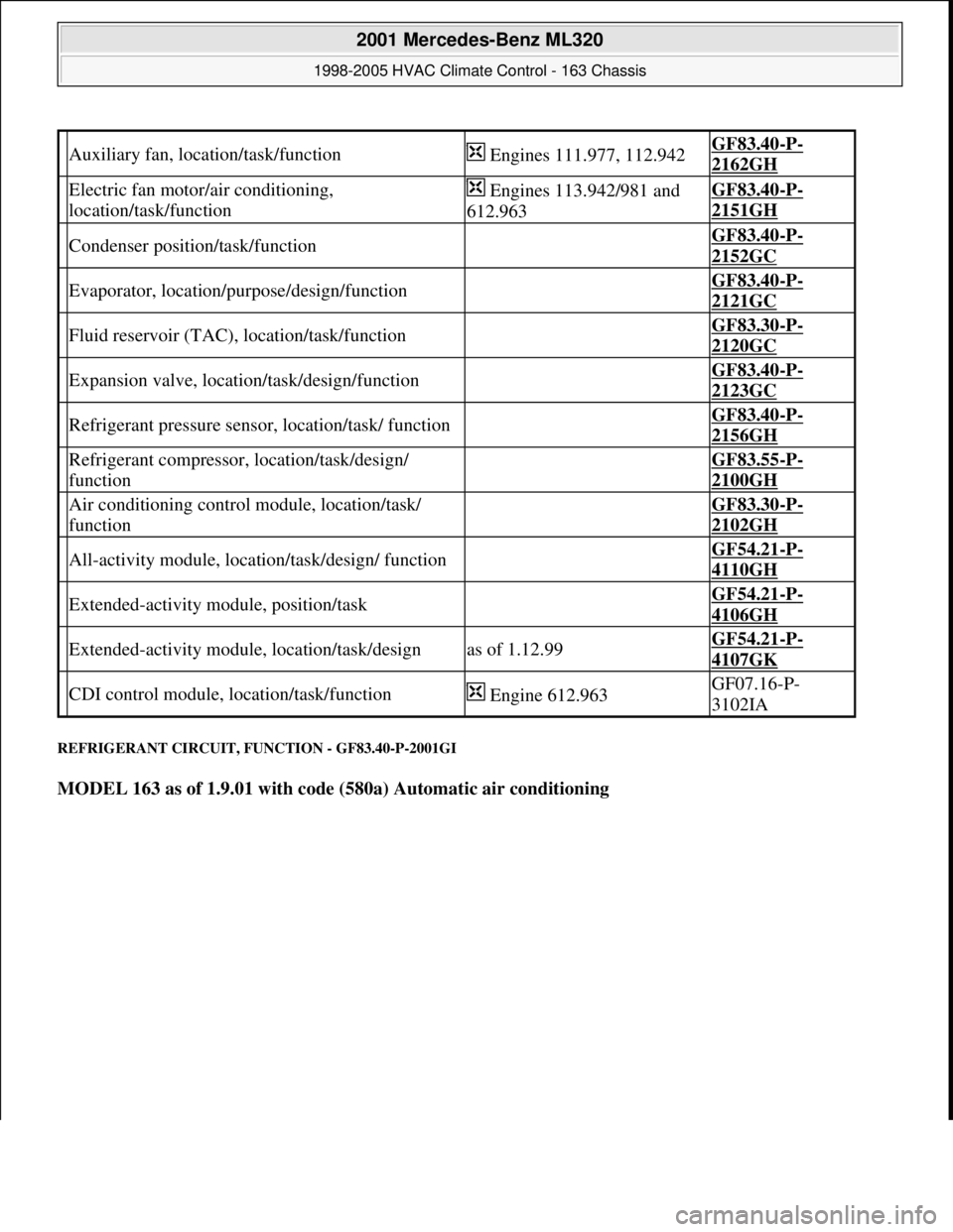
REFRIGERANT CIRCUIT, FUNCTION - GF83.40-P-2001GI
MODEL 163 as of 1.9.01 with code (580a) Automatic air conditioning
Auxiliary fan, location/task/function Engines 111.977, 112.942GF83.40-P-
2162GH
Electric fan motor/air conditioning,
location/task/function Engines 113.942/981 and
612.963GF83.40-P-
2151GH
Condenser position/task/function GF83.40-P-
2152GC
Evaporator, location/purpose/design/function GF83.40-P-
2121GC
Fluid reservoir (TAC), location/task/function GF83.30-P-
2120GC
Expansion valve, location/task/design/function GF83.40-P-
2123GC
Refrigerant pressure sensor, location/task/ function GF83.40-P-
2156GH
Refrigerant compressor, location/task/design/
function GF83.55-P-
2100GH
Air conditioning control module, location/task/
function GF83.30-P-
2102GH
All-activity module, location/task/design/ function GF54.21-P-
4110GH
Extended-activity module, position/task GF54.21-P-
4106GH
Extended-activity module, location/task/designas of 1.12.99GF54.21-P-
4107GK
CDI control module, location/task/function Engine 612.963GF07.16-P-
3102IA
2001 Mercedes-Benz ML320
1998-2005 HVAC Climate Control - 163 Chassis
me
Saturday, October 02, 2010 3:23:16 PMPage 86 © 2006 Mitchell Repair Information Company, LLC.
Page 3332 of 4133
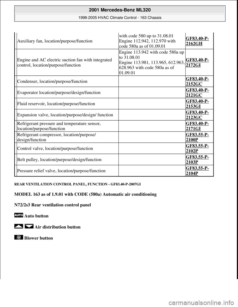
REAR VENTILATION CO NTROL PANEL, FUNCTION - GF83.40-P-2007GI
MODEL 163 as of 1.9.01 with CODE (580a) Automatic air conditioning
N72/2s3 Rear ventilation control panel
Auto button
Air distribution button
Blower button
Auxiliary fan, location/purpose/function
with code 580 up to 31.08.01
Engine 112.942, 112.970 with
code 580a as of 01.09.01GF83.40-P-
2162GH
Engine and AC electric su ction fan with integrated
control, location/purpose/function
Engine 113.942 with code 580a up
to 31.08.01
Engine 113.981, 113.965, 612.963,
628.963 with code 580a as of
01.09.01
GF83.40-P-
2172GI
Condenser, location/purpose/function GF83.40-P-
2152GC
Evaporator location/purpose/design/function GF83.40-P-
2121GC
Fluid reservoir, location/purpose/function GF83.40-P-
2153GI
Expansion valve, locati on/purpose/design/ function GF83.40-P-
2123GC
Refrigerant pressure and temperature sensor,
location/purpose/function GF83.40-P-
2171GI
Refrigerant compressor, location/purpose/
design/function GF83.55-P-
2100P
Control valve, location/purpose/function GF83.55-P-
2102P
Belt pulley, location/ purpose/design/function GF83.55-P-
2103P
Pressure relief valve, location/purpose/function GF83.55-P-
2104P
2001 Mercedes-Benz ML320
1998-2005 HVAC Climate Control - 163 Chassis
me
Saturday, October 02, 2010 3:23:16 PMPage 88 © 2006 Mitchell Repair Information Company, LLC.