Page 3471 of 4133
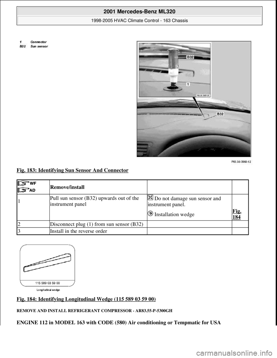
Fig. 183: Identifying Sun Sensor And Connector
Fig. 184: Identifying Longitudinal Wedge (115 589 03 59 00)
REMOVE AND INSTALL REFRIGERANT COMPRESSOR - AR83.55-P-5300GH
ENGINE 112 in MODEL 163 with CODE (580) Air conditioning or Tempmatic for USA
Remove/install
1Pull sun sensor (B32) upwards out of the
instrument panel Do not damage sun sensor and
instrument panel.
Installation wedgeFig.
184
2Disconnect plug (1) from sun sensor (B32)
3Install in the reverse order
2001 Mercedes-Benz ML320
1998-2005 HVAC Climate Control - 163 Chassis
me
Saturday, October 02, 2010 3:23:19 PMPage 227 © 2006 Mitchell Repair Information Company, LLC.
Page 3472 of 4133
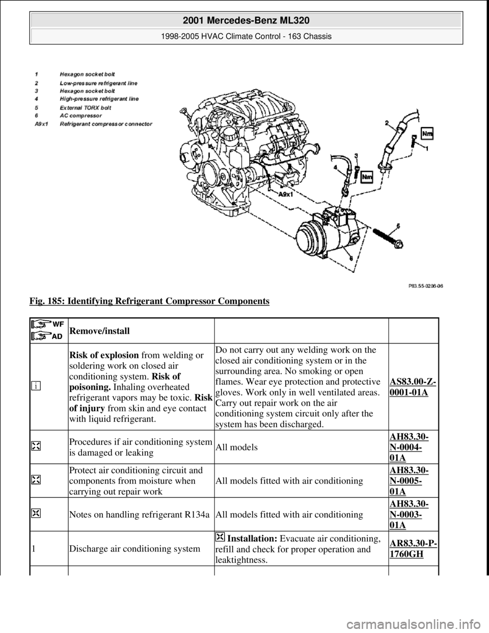
Fig. 185: Identifying Refrigerant Compressor Components
Remove/install
Risk of explosion from welding or
soldering work on closed air
conditioning system. Risk of
poisoning. Inhaling overheated
refrigerant vapors may be toxic. Risk
of injury from skin and eye contact
with liquid refrigerant.Do not carry out any welding work on the
closed air conditioning system or in the
surrounding area. No smoking or open
flames. Wear eye protection and protective
gloves. Work only in well ventilated areas.
Carry out repair work on the air
conditioning system circuit only after the
system has been discharged.
AS83.00-Z-
0001-01A
Procedures if air conditioning system
is damaged or leakingAll models
AH83.30-
N-0004-
01A
Protect air conditioning circuit and
components from moisture when
carrying out repair work
All models fitted with air conditioning
AH83.30-
N-0005-
01A
Notes on handling refrigerant R134aAll models fitted with air conditioning
AH83.30-
N-0003-
01A
1Discharge air conditioning system
Installation: Evacuate air conditioning,
refill and check for proper operation and
leaktightness.AR83.30-P-
1760GH
2001 Mercedes-Benz ML320
1998-2005 HVAC Climate Control - 163 Chassis
me
Saturday, October 02, 2010 3:23:19 PMPage 228 © 2006 Mitchell Repair Information Company, LLC.
Page 3473 of 4133
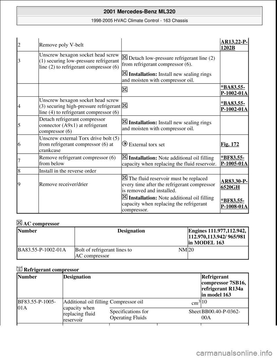
AC compressor
Refrigerant compressor
2Remove poly V-belt AR13.22-P-
1202B
3
Unscrew hexagon socket head screw
(1) securing low-pressure refrigerant
line (2) to refrigerant compressor (6) Detach low-pressure refrigerant line (2)
from refrigerant compressor (6).
Installation: Install new sealing rings
and moisten with compressor oil.
*BA83.55-
P-1002-01A
4
Unscrew hexagon socket head screw
(3) securing high-pressure refrigerant
line (4) to refrigerant compressor (6)
*BA83.55-
P-1002-01A
5
Detach refrigerant compressor
connector (A9x1) at refrigerant
compressor (6) Installation: Install new sealing rings
and moisten with compressor oil.
6
Unscrew external Torx drive bolt (5)
from refrigerant compressor (6) at
crankcase
External torx setFig. 172
7Remove refrigerant compressor (6)
from below Installation: Note additional oil filling
capacity when replacing the fluid reservoir.*BF83.55-
P-1005-01A
8Install in the reverse order
9Remove receiver/drier
The fluid reservoir must be replaced
every time after the refrigerant compressor
is removed and installed.AR83.30-P-
6520GH
Installation: Note additional oil filling
capacity when replacing the refrigerant
compressor.*BF83.55-
P-1008-01A
NumberDesignationEngines 111.977,112.942,
112.970,113.942/ 965/981
in MODEL 163
BA83.55-P-1002-01ABolt of refrigerant lines to
AC compressorNM20
NumberDesignationRefrigerant
compressor 7SB16,
refrigerant R134a
in model 163
BF83.55-P-1005-
01AAdditional oil filling
capacity when
replacing fluid
reservoirCompressor oilcm3 10
Specifications for
Operating FluidsSheetBB00.40-P-0362-
00A
2001 Mercedes-Benz ML320
1998-2005 HVAC Climate Control - 163 Chassis
me
Saturday, October 02, 2010 3:23:19 PMPage 229 © 2006 Mitchell Repair Information Company, LLC.
Page 3474 of 4133
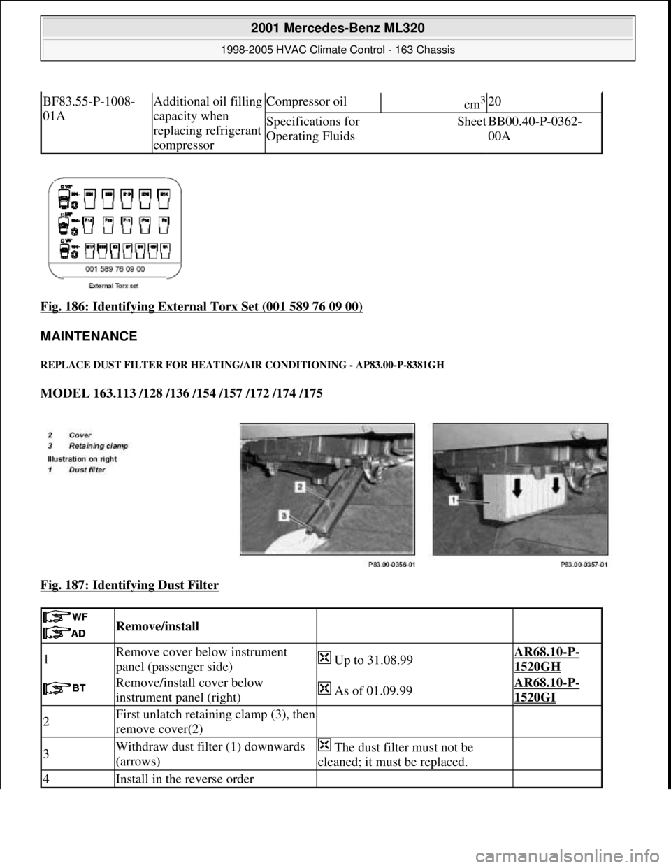
Fig. 186: Identifying External Torx Set (001 589 76 09 00)
MAINTENANCE
REPLACE DUST FILTER FOR HEATIN G/AIR CONDITIONING - AP83.00-P-8381GH
MODEL 163.113 /128 /136 /154 /157 /172 /174 /175
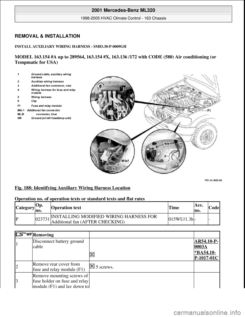
Fig. 187: Identifying Dust Filter
BF83.55-P-1008-
01AAdditional oil filling
capacity when
replacing refrigerant
compressorCompressor oilcm3 20
Specifications for
Operating FluidsSheetBB00.40-P-0362-
00A
Remove/install
1Remove cover below instrument
panel (passenger side) Up to 31.08.99AR68.10-P-
1520GH
Remove/install cover below
instrument panel (right) As of 01.09.99AR68.10-P-
1520GI
2First unlatch retaining clamp (3), then
remove cover(2)
3Withdraw dust filter (1) downwards
(arrows) The dust filter must not be
cleaned; it must be replaced.
4Install in the reverse order
2001 Mercedes-Benz ML320
1998-2005 HVAC Climate Control - 163 Chassis
me
Saturday, October 02, 2010 3:23:19 PMPage 230 © 2006 Mitchell Repair Information Company, LLC.
Page 3475 of 4133
REMOVAL & INSTALLATION
INSTALL AUXILIARY WIRING HARNESS - SM83.30-P-0009GH
MODEL 163.154 #A up to 289564, 163.154 #X, 163.136 /172 with CODE (580) Air conditioning (or
Tempmatic for USA)
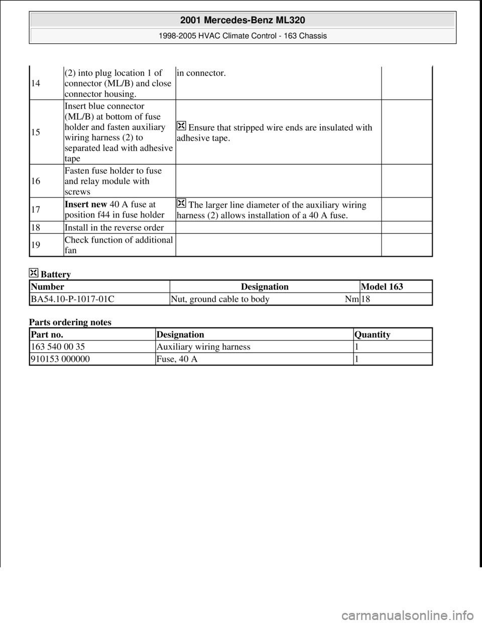
Fig. 188: Identifying Auxiliary Wiring Harness Location
Operation no. of operation texts or standard texts and flat rates
CategoryOp.
no.Operation textTimeAcc.
no.Code
P023731INSTALLING MODIFIED WIRING HARNESS FOR
Additional fan (AFTER CHECKING)015WU/1.3h--
Removing
1Disconnect battery ground
cable AR54.10-P-
0003A
*BA54.10-
P-1017-01C
2Remove rear cover from
fuse and relay module (F1) 5 screws.
3
Remove mounting screws of
fuse holder on fuse and relay
module (F1) and lay down to
2001 Mercedes-Benz ML320
1998-2005 HVAC Climate Control - 163 Chassis
me
Saturday, October 02, 2010 3:23:19 PMPage 231 © 2006 Mitchell Repair Information Company, LLC.
Page 3476 of 4133
side
4
Disconnect blue connector
(ML/B) from bottom of fuse
holder
5Remove lamp unit AR82.10-P-
4730GH
6
Remove original additional
fan connector (M4x1) from
additional fan and fasten to
present wiring harness (5)
with adhesive tape on clip
(6)
Install
7
Route new additional fan
connector (3) on auxiliary
wiring harness (2) to
additional fan connector and
insert
Route along original wiring harness at rear of
installation opening of lamp unit
8
Fasten auxiliary wiring
harness (2) to original wiring
harness in area of clips with
cable straps.
9
Fasten auxiliary wiring
harness ground cable (1) to
left front ground (W9)
*BA54.10-
P-1017-01C
10
Route auxiliary wiring
harness (2) into fuse and
relay module
Route fuse and relay module along wiring harness
for fuse and relay module (4) below installation
opening of lamp unit between washer water reservoir
and fender to grommet on left side of fuse and relay
module. Remove adhesive tape from rubber
grommet, thread wiring harness through and reinstall
adhesive tape.
11
Route connection terminal
of auxiliary wiring harness
(2) to blue connector
(ML/B) at bottom of fuse
holder
12
Open housing of connector
(ML/B) and remove lead
from plug location 1
13
Separate present lead
approx. 100 mm in front
connection terminal
Insert connection terminal
for auxiliary wiring harness
Ensure that connection terminal arrests correctly
2001 Mercedes-Benz ML320
1998-2005 HVAC Climate Control - 163 Chassis
me
Saturday, October 02, 2010 3:23:19 PMPage 232 © 2006 Mitchell Repair Information Company, LLC.
Page 3477 of 4133
Battery
Parts ordering notes
14
(2) into plug location 1 of
connector (ML/B) and close
connector housing.in connector.
15
Insert blue connector
(ML/B) at bottom of fuse
holder and fasten auxiliary
wiring harness (2) to
separated lead with adhesive
tape
Ensure that stripped wire ends are insulated with
adhesive tape.
16
Fasten fuse holder to fuse
and relay module with
screws
17Insert new 40 A fuse at
position f44 in fuse holder The larger line diameter of the auxiliary wiring
harness (2) allows installation of a 40 A fuse.
18Install in the reverse order
19Check function of additional
fan
NumberDesignationModel 163
BA54.10-P-1017-01CNut, ground cable to bodyNm18
Part no.DesignationQuantity
163 540 00 35Auxiliary wiring harness1
910153 000000Fuse, 40 A1
2001 Mercedes-Benz ML320
1998-2005 HVAC Climate Control - 163 Chassis
me
Saturday, October 02, 2010 3:23:19 PMPage 233 © 2006 Mitchell Repair Information Company, LLC.