Page 1882 of 4133

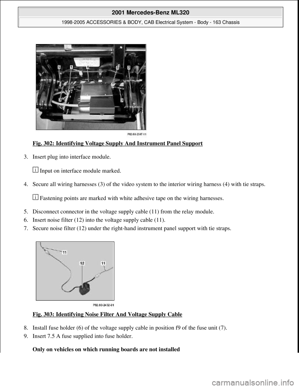
Fig. 302: Identifying Voltage Supply And Instrument Panel Support
3. Insert plug into interface module.
Input on interface module marked.
4. Secure all wiring harnesses (3) of the video system to the interior wiring harness (4) with tie straps.
Fastening points are marked with white adhesive tape on the wiring harnesses.
5. Disconnect connector in the voltage supply cable (11) from the relay module.
6. Insert noise filter (12) into the voltage supply cable (11).
7. Secure noise filter (12) under the right-hand instrument panel support with tie straps.
Fig. 303: Identifying Noise Filter And Voltage Supply Cable
8. Install fuse holder (6) of the voltage supply cable in position f9 of the fuse unit (7).
9. Insert 7.5 A fuse supplied into fuse holder.
Only on vehicles on which running boards are not installed
2001 Mercedes-Benz ML320
1998-2005 ACCESSORIES & BODY, CAB Electrical System - Body - 163 Chassis
me
Saturday, October 02, 2010 3:30:12 PMPage 387 © 2006 Mitchell Repair Information Company, LLC.
Page 2037 of 4133

Fig. 1: Drive Belt Routing
Courtesy of MERCEDES-BENZ OF NORTH AMERICA.
TROUBLE SHOOTING
PRELIMINARY INSPECTION
Verify customer complaint by operating system. Visually inspect for obvious signs of mechanical and electrical
damage. Check generator belt tension and condition. Ensure that battery voltage is within specifications. Inspect
for blown fuses and damaged relays.
Verify ground connection integrity between engine, body, battery and generator. Check for damaged wiring
harnesses and/or switches. Check for a broken or partially broken wire inside insulation, which could cause
system malfunction but prove good in a continuity/voltage check with system disconnected. Ensure any
aftermarket electronic equipment is properly installed. If fault is found, repair as necessary. If no fault is found,
check for conditions that might cause an intermittent situation.
SERVICE PRECAUTIONS
BATTERY DISCONNECT/CONNECT
Disconnect Procedures
1. On vehicles not equipped with TELE AID, go to step 5 . Vehicles equipped with TELE AID, switch
TELE AID into service mode by turning ignition ON.
2. Turn ON telephone and enter code "*#4610#" on handset.
3. Confirm that "No Telematics Service" appears on handset with okay.
4. Turn OFF handset.
5. Turn OFF ignition.
6. Open hood and open snap fasteners (1) on dust filter housing. See Fig. 2
.
7. Remove dust filter housing (2) exposing battery.
8. If not using quiescent current retention unit, go to step 14 . If using quiescent current retention unit, go to
next step.
9. Connect quiescent current retention unit by switching on quiescent current retention unit (7) and then first
connecting positive terminal (8) and negative terminal (9) of retention unit to positive cable and battery
ground (W10). See Fig. 3
.
10. On vehicles equipped with TELE AID, remove luggage compartment cargo anchoring lugs and remove
floor paneling.
11. Remove screws (1). See Fig. 4
.
12. Dismantle cover from TELE AID control module (A35/8).
13. Disconnect connection coupling for back up battery and remove back up battery.
14. Disconnect ne
gative battery cable (1) and insulate terminal. See Fig. 5. NOTE: Numbers and letters in text refer to numbers and letters in figures.
2001 Mercedes-Benz ML320
2001-04 STARTING & CHARGING SYSTEMS Generators & Regulators - 163 Chassis
me
Saturday, October 02, 2010 3:20:31 PMPage 3 © 2006 Mitchell Repair Information Company, LLC.
Page 2038 of 4133
Fig. 2: Removing Dust Filter Housing
Courtesy of MERCEDES-BENZ OF NORTH AMERICA.
2001 Mercedes-Benz ML320
2001-04 STARTING & CHARGING SYSTEMS Generators & Regulators - 163 Chassis
me
Saturday, October 02, 2010 3:20:31 PMPage 4 © 2006 Mitchell Repair Information Company, LLC.
Page 2085 of 4133
AR01.30-P-5800MV
Remove/install cylinder head
22.7.98
ENGINE
112.942 in MODEL 163.154
ENGINE
112.970 in MODEL 163.157
ENGINE
113.942 in MODEL 163.172
ENGINE
113.981 in MODEL 163.174
ENGINE
113.965 in MODEL 163.175
P01.30-2032-06
Shown on model 163.154 with engine 112
1
Air baffle
2
Viscous fan
3
Fan shroud
4
Bolts
5
Air cleaner housing
6
Air intake manifold
7
Resonance unit
8
Poly-V-belt
9
Fender liner
10
Shield
11
Exhaust bracket
P01.30-2033-06
12
Right and left ignition coils
13
Left and right cylinder head covers
14
Intake manifold
15
Camshaft position sensor
16
Coolant line
17
Chain tensioner
18
Oil filter housing
19
Camshaft sprockets
28
Camshaft bearing bridges
Copyright DaimlerChrysler AG 20.05.2006 CD-Ausgabe G/10/04 . This WIS print-out will not be recorde
d by Modification services.
Page 1
Page 2093 of 4133
AR01.30-P-5800MV
Remove/install cylinder head
22.7.98
ENGINE
112.942 in MODEL 163.154
ENGINE
112.970 in MODEL 163.157
ENGINE
113.942 in MODEL 163.172
ENGINE
113.981 in MODEL 163.174
ENGINE
113.965 in MODEL 163.175
P01.30-2032-06
Shown on model 163.154 with engine 112
1
Air baffle
2
Viscous fan
3
Fan shroud
4
Bolts
5
Air cleaner housing
6
Air intake manifold
7
Resonance unit
8
Poly-V-belt
9
Fender liner
10
Shield
11
Exhaust bracket
P01.30-2033-06
12
Right and left ignition coils
13
Left and right cylinder head covers
14
Intake manifold
15
Camshaft position sensor
16
Coolant line
17
Chain tensioner
18
Oil filter housing
19
Camshaft sprockets
28
Camshaft bearing bridges
Copyright DaimlerChrysler AG 20.05.2006 CD-Ausgabe G/10/04 . This WIS print-out will not be recorde
d by Modification services.
Page 1
Page 2193 of 4133

version FB6 with code ZS6, -
special protection version FB7
with code ZS7, additional battery
100 Ah incl. cutoff relay code E26.
Model 463.248 with: special
protection version, code 979, -
special protection version FB6,
code ZS6, -special protection
version FB7, code ZS7, -additional
battery 100 Ah including cutoff
relay, code E26.AR54.10-P-0003PM
3.1Unclip cover on front
side of engineModel 211, 215, 220, 230.475/476
4.1Remove engine cover
with integrated air filterExcept model 170.466,
203.065/076/265/276, 209.376/476
from 24.4.04, 211.076/276,
215.374, 220.074/174, 230.474,
463.270/271
The air filter is integrated in the
engine cover. Remove the engine
cover or the air filter housing by
pulling it from the cylinder head
covers vertically in the upward
direction.
4.2Remove air filter housingModel 170.466, 203.065/265,
211.076/276, 215.374,
220.074/174, 230.474AR09.10-P-1150SVK
Model 203.076 /276, 209.376 /476
from 24.4.04, 171.473AR09.10-P-1150AC
Model 463.270/271AR09.10-P-1150GX
5Unscrew screw (5/3) *BA15.10-P-1001-
04A
6Detach spark plug
connector (5/1) from the
spark plugs Pry off spark plug connector
(5/1) using open-end wrench,
double over the cylinder head
cover of the spark plugs.
Installation: Observe the
identification of the connector
(arrow) on the cylinder head cover
and the ignition coil of cylinders 1
to 6 or 1 to 8 for the corresponding
spark plug connector (5/1).
Double open-ended wrenchFig. 24
7Separate electrical
connector of ignition coil
of cylinder 1 to 6 (T1/1 Installation: Install new cable
ties.
2001 Mercedes-Benz ML320
1998-2005 ENGINE Electrical System - Engine - 163 Chassis
me
Saturday, October 02, 2010 3:18:54 PMPage 39 © 2006 Mitchell Repair Information Company, LLC.
Page 2197 of 4133

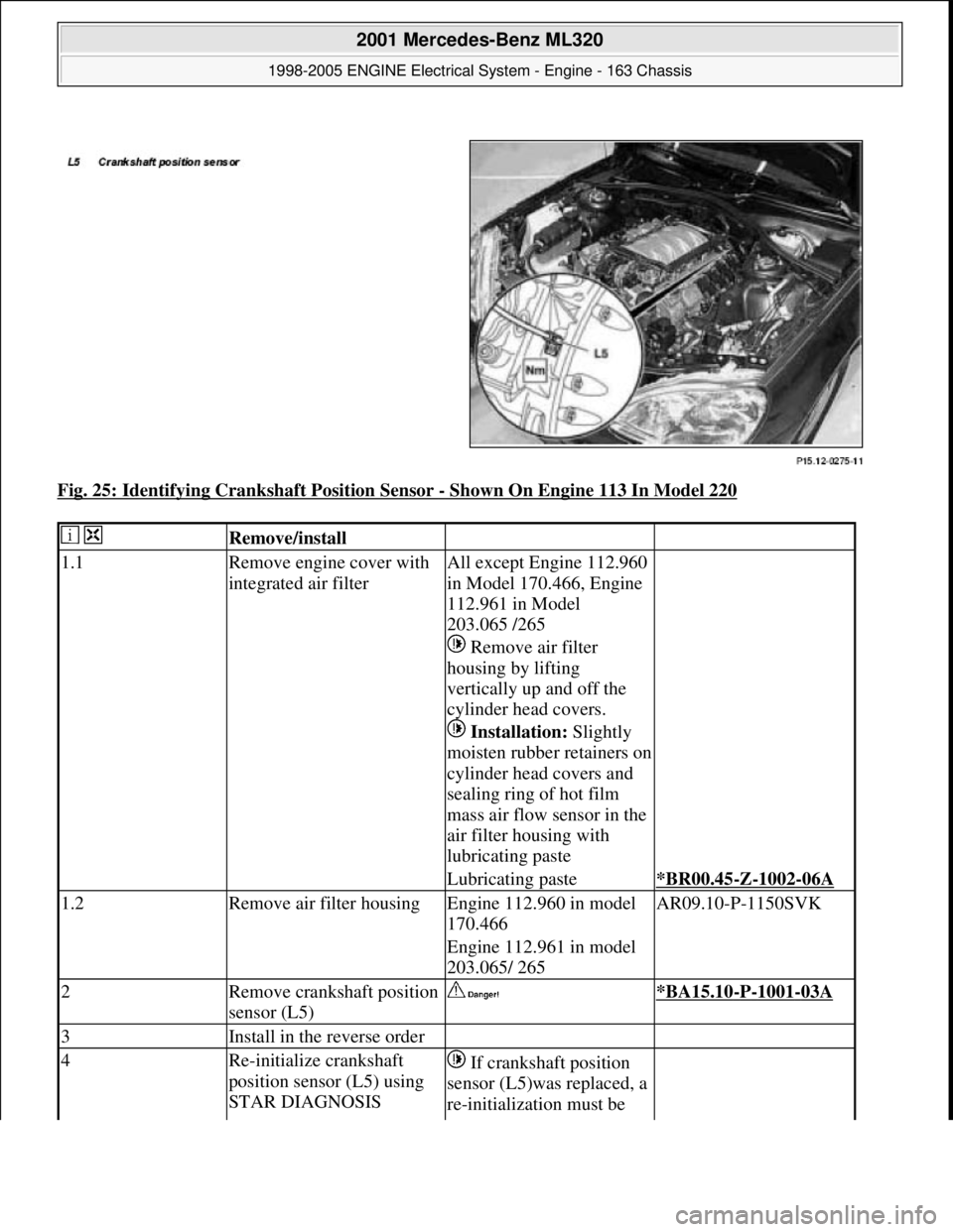
Fig. 25: Identifying Crankshaft Position Sensor - Shown On Engine 113 In Model 220
Remove/install
1.1Remove engine cover with
integrated air filterAll except Engine 112.960
in Model 170.466, Engine
112.961 in Model
203.065 /265
Remove air filter
housing by lifting
vertically up and off the
cylinder head covers.
Installation: Slightly
moisten rubber retainers on
cylinder head covers and
sealing ring of hot film
mass air flow sensor in the
air filter housing with
lubricating paste
Lubricating paste*BR00.45-Z-1002-06A
1.2Remove air filter housingEngine 112.960 in model
170.466AR09.10-P-1150SVK
Engine 112.961 in model
203.065/ 265
2Remove crankshaft position
sensor (L5) *BA15.10-P-1001-03A
3Install in the reverse order
4Re-initialize crankshaft
position sensor (L5) using
STAR DIAGNOSIS If crankshaft position
sensor (L5)was replaced, a
re-initialization must be
2001 Mercedes-Benz ML320
1998-2005 ENGINE Electrical System - Engine - 163 Chassis
me
Saturday, October 02, 2010 3:18:54 PMPage 43 © 2006 Mitchell Repair Information Company, LLC.
Page 2226 of 4133
Fig. 47: Identifying Spark Plugs And Cylinder 4 Ignition Coil
Remove/install and
replacing
Risk of death due to
contact with high-voltage
conductive partsDo not touch parts which
conduct high voltages.
Persons who are carriers
of electronic implants
(e.g. cardiac pacemaker)
may not carry out any
work on the ignition
systemAS15.10-Z-0001-01A
Notes on avoiding damage
to ignition systemEngine 104, 111, 112,
113, 119, 120,271AH15.10-P-0002-01D
1Remove/install air filter
upper section
2
Remove ignition coils
Remove/install ignition
coils
AR15.12-P-2003A
3Disconnect spark plug
connectors Prise over cylinder
head cover.
Double open-ended
wrenchFig. 24
Checking
4Check spark plug Replace, if necessary.
2001 Mercedes-Benz ML320
1998-2005 ENGINE Electrical System - Engine - 163 Chassis
me
Saturday, October 02, 2010 3:18:55 PMPage 72 © 2006 Mitchell Repair Information Company, LLC.