1997 MERCEDES-BENZ ML430 window
[x] Cancel search: windowPage 3272 of 4133
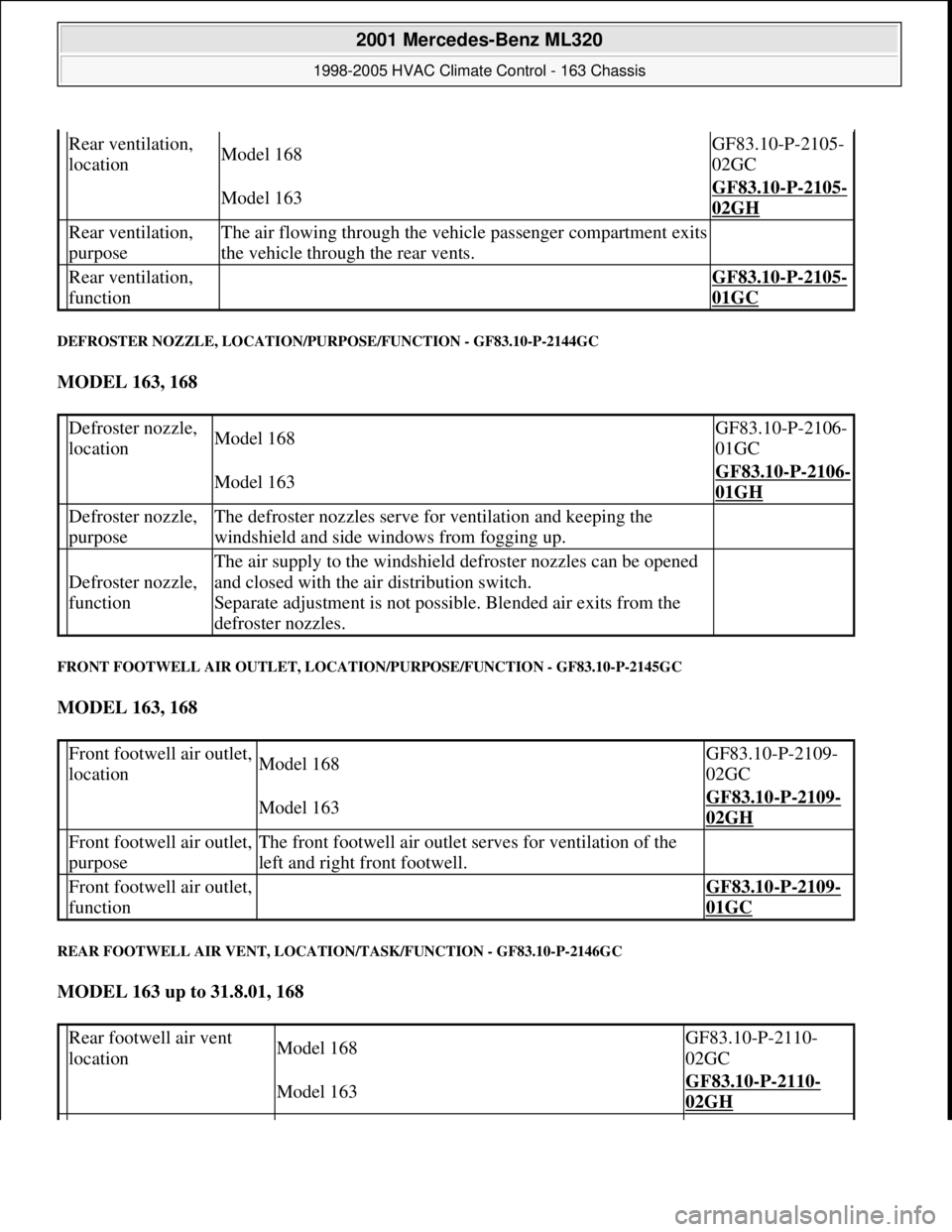
DEFROSTER NOZZLE, LOCATION/PURPOSE/FUNCTION - GF83.10-P-2144GC
MODEL 163, 168
FRONT FOOTWELL AIR OUTLET, LOCATION/PURPOSE/FUNCTION - GF83.10-P-2145GC
MODEL 163, 168
REAR FOOTWELL AIR VENT, LOCATION/TASK/FUNCTION - GF83.10-P-2146GC
MODEL 163 up to 31.8.01, 168
Rear ventilation,
locationModel 168GF83.10-P-2105-
02GC
Model 163GF83.10-P-2105-
02GH
Rear ventilation,
purposeThe air flowing through the vehicle passenger compartment exits
the vehicle through the rear vents.
Rear ventilation,
function GF83.10-P-2105-
01GC
Defroster nozzle,
locationModel 168GF83.10-P-2106-
01GC
Model 163GF83.10-P-2106-
01GH
Defroster nozzle,
purposeThe defroster nozzles serve for ventilation and keeping the
windshield and side windows from fogging up.
Defroster nozzle,
function
The air supply to the windshield defroster nozzles can be opened
and closed with the air distribution switch.
Separate adjustment is not possible. Blended air exits from the
defroster nozzles.
Front footwell air outlet,
locationModel 168GF83.10-P-2109-
02GC
Model 163GF83.10-P-2109-
02GH
Front footwell air outlet,
purposeThe front footwell air outlet serves for ventilation of the
left and right front footwell.
Front footwell air outlet,
function GF83.10-P-2109-
01GC
Rear footwell air vent
locationModel 168GF83.10-P-2110-
02GC
Model 163GF83.10-P-2110-
02GH
2001 Mercedes-Benz ML320
1998-2005 HVAC Climate Control - 163 Chassis
me
Saturday, October 02, 2010 3:23:15 PMPage 28 © 2006 Mitchell Repair Information Company, LLC.
Page 3284 of 4133
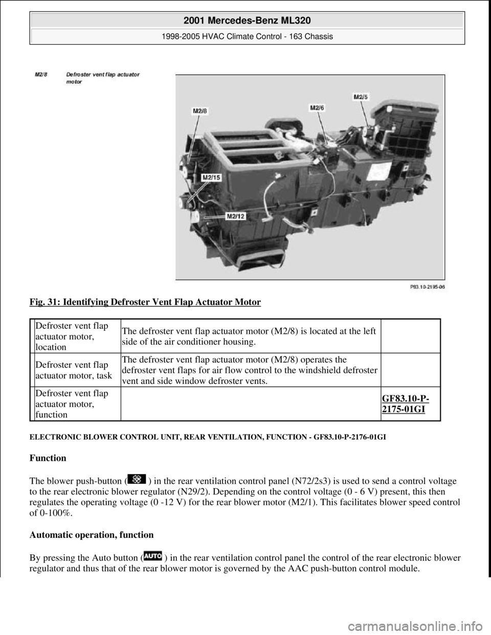
Fig. 31: Identifying Defroster Vent Flap Actuator Motor
ELECTRONIC BLOWER CONTROL UNIT, REAR VENTILATION, FUNCTION - GF83.10-P-2176-01GI
Function
The blower push-button ( ) in the rear ventilation control panel (N72/2s3) is used to send a control voltage
to the rear electronic blower regulator (N29/2). Depe nding on the control voltage (0 - 6 V) present, this then
regulates the operating voltage (0 -12 V) for the rear blow er motor (M2/1). This facilitates blower speed control
of 0-100%.
Automatic operation, function
By pressing the Auto button ( ) in th e rear ventilation control panel the control of the rear electronic blower
re
gulator and thus that of the rear blower motor is governed by the AAC push-button control module.
Defroster vent flap
actuator motor,
locationThe defroster vent flap actuator moto r (M2/8) is located at the left
side of the air conditioner housing.
Defroster vent flap
actuator motor, taskThe defroster vent flap actua tor motor (M2/8) operates the
defroster vent flaps for air flow control to the windshield defroster
vent and side window defroster vents.
Defroster vent flap
actuator motor,
function
GF83.10-P-
2175-01GI
2001 Mercedes-Benz ML320
1998-2005 HVAC Climate Control - 163 Chassis
me
Saturday, October 02, 2010 3:23:15 PMPage 40 © 2006 Mitchell Repair Information Company, LLC.
Page 3299 of 4133
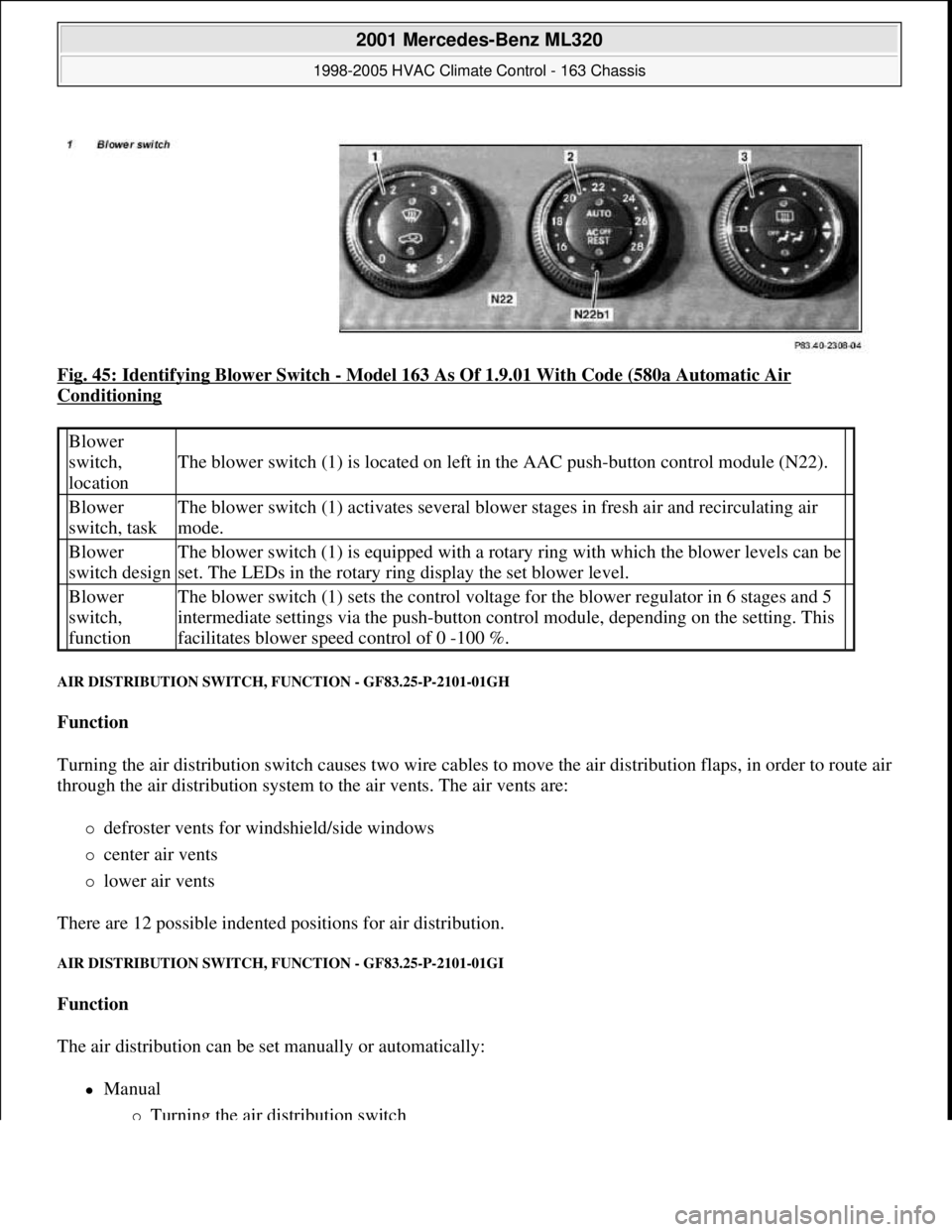
Fig. 45: Identifying Blower Switch - Model 163 As Of 1.9.01 With Code (580a Automatic Air
Conditioning
AIR DISTRIBUTION SWITCH, FUNCTION - GF83.25-P-2101-01GH
Function
Turning the air distribution switch causes two wire cables to move the air distribution flaps, in order to route air
through the air distribution system to the air vents. The air vents are:
defroster vents for windshield/side windows
center air vents
lower air vents
There are 12 possible indented positions for air distribution.
AIR DISTRIBUTION SWITCH, FUNCTION - GF83.25-P-2101-01GI
Function
The air distribution can be set manually or automatically:
Manual
Turning the air distribution switch
Blower
switch,
location
The blower switch (1) is located on left in the AAC push-button control module (N22).
Blower
switch, taskThe blower switch (1) activates several blower stages in fresh air and recirculating air
mode.
Blower
switch designThe blower switch (1) is equipped with a rotary ring with which the blower levels can be
set. The LEDs in the rotary ring display the set blower level.
Blower
switch,
functionThe blower switch (1) sets the control voltage for the blower regulator in 6 stages and 5
intermediate settings via the push-button control module, depending on the setting. This
facilitates blower speed control of 0 -100 %.
2001 Mercedes-Benz ML320
1998-2005 HVAC Climate Control - 163 Chassis
me
Saturday, October 02, 2010 3:23:15 PMPage 55 © 2006 Mitchell Repair Information Company, LLC.
Page 3304 of 4133
After starting, the refrigerant compressor starts up. If cooling is not necessary, the refrigerant compressor's
output is lowered and switched off via the icing inhibitor.
The air conditioning is always ready for operation after the engine has been started, and operates according to
the so-called "reheat" principle. This means: The refrigerant compressor always operates at an ambient
temperature in excess of 1°C, therefore also cools cold incoming air. Following the cooling process, the dried
air is heated at the heat exchanger.
On the one hand, this effect serves the purpose of comfort, because cooling also simultaneously causes air
dehumidification which, in turn, is an important prerequisite for a pleasant interior climate. On the other hand,
the air is dried as a result of this cooling and heating, thereby preventing window fogging.
Pressing the AC button again ( ) (does not illuminate) switches off the cooling.
Heating mode
The in-car temperature sensor measures the air temperature in the interior of the vehicle.
The air conditioning control module electronics compares the in-car temperature with the desired temperature
which has been set at the temperature selector wheels.
The microprocessor adjusts the air conditioning electronics or keeps the relevant setting constant as required.
Heater operation with heater booster in vehicles with engine 612.963 as of 12/99
In vehicles equipped with direct-injection diesel engines, an electrical heater booster is additionally installed in
the evaporator housing downstream of the heat exchanger, in order to compensate any heater output deficit
which exists under certain operating conditions.
The 3 heating elements in the heater booster are supplied with current, whereupon they are heated and they start
to glow. As a result of the structural conditions, it is ensured that the drawn in fresh air flows directly past the
electric heater booster, and is therefore heated.
Cooling mode
The icing inhibitor measures the temperature at the evaporator air outlet, while the interior temperature sensor
determines the relevant in-car temperature.
The air conditioning control module electronics compares the various measured values with the desired
temperature which has been set at the temperature selector wheels.
The microprocessor adjusts the air conditioning or keeps the relevant setting constant as required.
In-car temperature sensor replaced by new typeas of 1.12.99BT83.57-P-0001-04GH
Ventilation, function GF83.10-P-2000GH
Heater circuit function GF83.20-P-2003GH
2001 Mercedes-Benz ML320
1998-2005 HVAC Climate Control - 163 Chassis
me
Saturday, October 02, 2010 3:23:15 PMPage 60 © 2006 Mitchell Repair Information Company, LLC.
Page 3327 of 4133
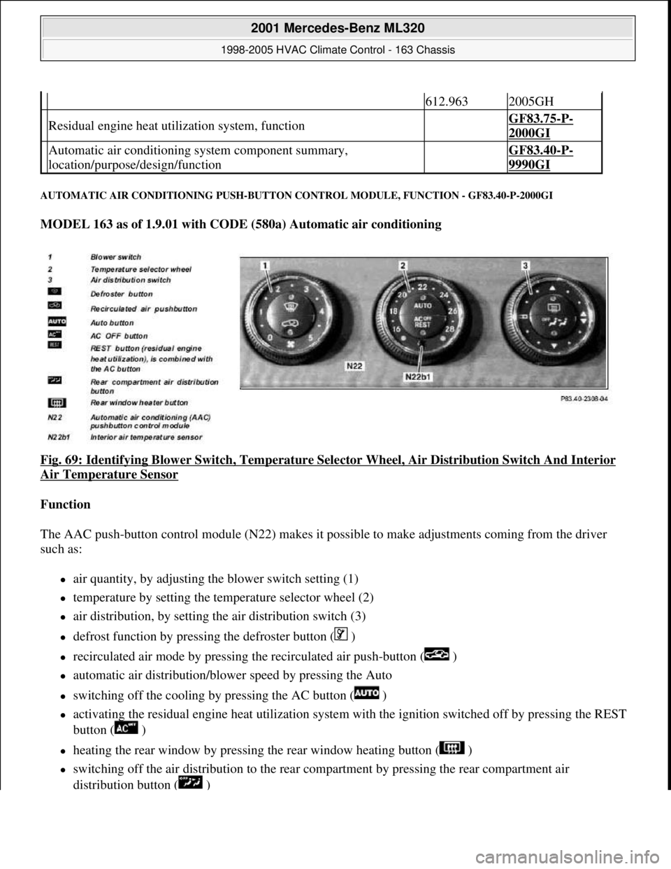
AUTOMATIC AIR CONDITIONING PUSH-BUTTON CONTROL MODULE, FUNCTION - GF83.40-P-2000GI
MODEL 163 as of 1.9.01 with CODE (580a) Automatic air conditioning
Fig. 69: Identifying Blower Switch , Temperature Selector Wheel, Air Di stribution Switch And Interior
Air Temperature Sensor
Function
The AAC push-button control module (N 22) makes it possible to make adjustments coming from the driver
such as:
air quantity, by adjusting the blower switch setting (1)
temperature by setting the temp erature selector wheel (2)
air distribution, by setting the air distribution switch (3)
defrost function by pressing the defroster button ( )
recirculated air mode by pressing th e recirculated air push-button ( )
automatic air distribution/blower speed by pressing the Auto
switching off the cooling by pressing the AC button ( )
activating the residual engine heat ut ilization system with the ignition switched of f by pressing the REST
button ( )
heating the rear window by pressing the rear window heating button ( )
switching off the air distribution to the rear compartment by pressing the rear compartment air
distribution button ( )
612.9632005GH
Residual engine heat util ization system, function GF83.75-P-
2000GI
Automatic air conditioning sy stem component summary,
location/purpose/design/function GF83.40-P-
9990GI
2001 Mercedes-Benz ML320
1998-2005 HVAC Climate Control - 163 Chassis
me
Saturday, October 02, 2010 3:23:16 PMPage 83 © 2006 Mitchell Repair Information Company, LLC.
Page 3328 of 4133
The control module integrated in the AAC push-button control module (N22) looks after all system regulation
and control functions such as:
comparing preselected and actual temperatures and controlling the air temperature at the air outlets
automatic switchover from fresh air to recirculated air mode
electrical control of refrigerant compressor
controlling the auxiliary fan or the electric suction-type fan motor/ air conditioning with integrated
control
The AAC push-button control module (N22) has a diagnostic capability. Consequently, any faults which occur
are stored in the fault memory which can be read with the help of the diagnosis assistant system (DAS).
When the AAC push-button control module is replaced (N22), variant coding must be carried out using the
Diagnosis Assistant System (DAS).
The AAC push-button control module (N22) also performs the following actuations:
direct: refrigerant compressor; heating water circulation pump; PTC heater booster (OM 612 only), rear
window heater
via the CAN BUS: auxiliary fan, electric suction-type fan motor/air conditioning with integrated control,
blower control and air distribution in the rear compartment (automatic mode)
via the AC bus: blower motor; 8 stepping motors for air distribution
The following sensor signals are read in by the AAC push-button control module (N22):
direct: temperature sensor evaporator, pressure and temperature sensor refrigerant, in-car temperature
sensor, center nozzle vent air temperature sensor, footwell and rear passenger compartment, sun sensor
via the CAN BUS: Ambient temperature display temperature sensor, sensor for specified values in rear
control panel
REFRIGERANT CIRCUIT FUNCTION - GF83.40-P-2001GH
MODEL 163 up to 31.8.01 with CODE (580) Air conditioning or Tempmatic for USA
Blower switch, location/task/design/function GF83.25-P-2100GI
Temperature selector wheel, location/task/ design/function GF83.25-P-2102GI
Air distribution switch, location/task/design/ function GF83.25-P-2101GI
Defroster button, location/task/function GF83.40-P-2139GI
Recirculating air push-button, location/task/ function GF83.40-P-2145GI
Auto button, location/task/function GF83.40-P-2147GI
AC OFF button, location/task/function GF83.40-P-2107GI
Rest push-button, location/task/function GF83.40-P-2148GI
Rear passenger compartment air distribution button, location/task/function GF83.40-P-2173GI
2001 Mercedes-Benz ML320
1998-2005 HVAC Climate Control - 163 Chassis
me
Saturday, October 02, 2010 3:23:16 PMPage 84 © 2006 Mitchell Repair Information Company, LLC.
Page 3334 of 4133
Air distribution button ( ) = air duc ting to rear compartment nozzle
Air distribution button ( ) = air ducting to the air outlets in the rear footwell
The automatic air distribution function can be set by pr essing the Auto button, whereby control is assumed by
the AAC push-button c ontrol module (N22).
RECIRCULATING AIR PU SH-BUTTON, FUNCTION - GF83.40-P-2102-01GI
Function
A brief actuation (< 1.5 s) of the recirculating air pus h-button ( ) energizes the actuator motor for the fresh
air/recirculated air flap, whic h activates the fresh air/recirculated air fl ap and thus closes the fresh air duct and
opens the recirculation duct, in or der to enable the air supply from the passenger compartment. The function
LED illuminates during recirculation mode.
Recirculated air convenience closing function
If the recirculating air pus h-button ( ) is pressed for longer than > 2 s, then alongside the recirculation
function, all open windows and the sliding and tilting roof are automatically closed (window and sliding/
tilting roof must ha ve been normalized ). The function LED illuminates durin g recirculation mode. In order to
prevent any current peaks the sliding/tilting sunroof and power windows are actuated successively.
If the push-button is pressed again for > 2 s, the windows a nd the sliding/tilting sunroof return to the previously
stored position and the fresh air/ recirculated air flap moves to the fresh air position (LED off).
The convenience closing function can only be started if the recirculating LED is not illuminated.
Each window, which has been manually opened during the r ecirculation phase, remains in this position if the
recirculating function is cleared: all other windows move to the stor ed positions. The position of the
sliding/tilting sunroof prior to the st art of the closing operation and that of the side windows is stored in the
memory. The windows and the sliding/tilting sunroof wh ich have been closed by the convenience closing
function, remain closed if the recirculation push-
button was only pressed briefly (t < 1.5 s). In this case, only the
fresh air/recirculated air flap is moved to the fresh-air position. The stored positions are cleared when the
ignition is switched off.
AUTOMATIC AIR CONDITIONING BOX FUNCTION - GF83.40-P-2105-02GI
Operating condition: Air ducting under heater operation
2001 Mercedes-Benz ML320
1998-2005 HVAC Climate Control - 163 Chassis
me
Saturday, October 02, 2010 3:23:16 PMPage 90 © 2006 Mitchell Repair Information Company, LLC.
Page 3350 of 4133
value.
At the following values the electric fan for engine/AC (M4/7) is switched on or off:
refrigerant pressure > 20 bar = electric fan for engine/AC ON
refrigerant pressure <12 bar = electric fan for engine/AC OFF
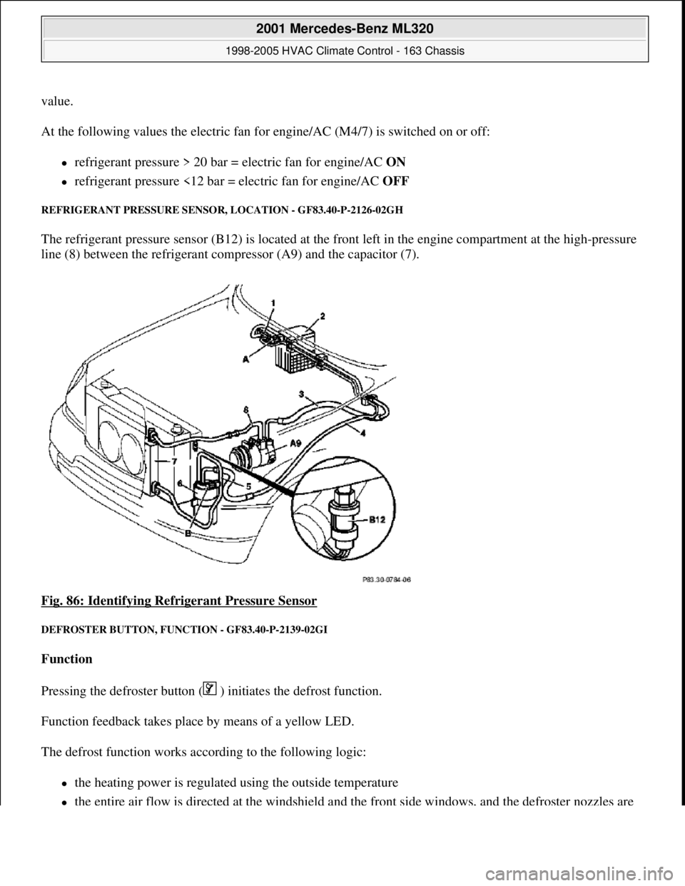
REFRIGERANT PRESSURE SENSOR, LOCATION - GF83.40-P-2126-02GH
The refrigerant pressure sensor (B12) is located at the front left in the engine compartment at the high-pressure
line (8) between the refrigerant compressor (A9) and the capacitor (7).
Fig. 86: Identifying Refrigerant Pressure Sensor
DEFROSTER BUTTON, FUNCTION - GF83.40-P-2139-02GI
Function
Pressing the defroster button ( ) initiates the defrost function.
Function feedback takes place by means of a yellow LED.
The defrost function works according to the following logic:
the heating power is regulated using the outside temperature
the entire air flow is directed at the windshield and the front side windows, and the defroster nozzles are
2001 Mercedes-Benz ML320
1998-2005 HVAC Climate Control - 163 Chassis
me
Saturday, October 02, 2010 3:23:16 PMPage 106 © 2006 Mitchell Repair Information Company, LLC.