Page 1874 of 4133
Fig. 293: Identifying Self-Adhesive Brackets, Blue Color Coding And Red Color Coding
RETROFIT WIRING HARNESS FOR AUXILIARY INTERFACE MODULE AND VIDEO/DVD PLAYER - AZ82.60-P-0004-03B
Models 163.113/154/174#A as of 289565, Model 163.113 #X as of 754620, Model 163.128/157/175
1. Make diagonal cut (a=50 mm) to floor lining of right rear corner of rear blower motor (M2/1).
Fig. 294: Identifying Rear Blower Motor, Cutout In Floor Lining And DVD Player Wiring Harness
2. Measure dimension (b=510 mm) from center of rear blower motor (M2/1) and dimension (c=120 mm)
from inner edge of cutout in floor lining under the 40% rear seat and mark the floor lining.
2001 Mercedes-Benz ML320
1998-2005 ACCESSORIES & BODY, CAB Electrical System - Body - 163 Chassis
me
Saturday, October 02, 2010 3:30:12 PMPage 379 © 2006 Mitchell Repair Information Company, LLC.
Page 1875 of 4133
Fig. 295: Identifying Dimension (b=510 mm) From Center Of Rear Blower Motor (M2/1)
3. Starting at the marking cut the floor lining towards the left-hand side of the vehicle (d=70 mm).
The incision should be located in the center of the transmission tunnel.
4. Cut floor lining from center of previous incision (d=70 mm) to vehicle rear (e=30 mm).
5. Route wiring harness video player (2) and wiring harness DVD player (3) from the incision to the rear of
the rear blower motor (M2/1) to the cutout in the floor lining under the 40% rear seat under the floor
lining.
Put down wiring harness for later routing.
Do not route wirin
g harness for additional interface module under the floor lining.
2001 Mercedes-Benz ML320
1998-2005 ACCESSORIES & BODY, CAB Electrical System - Body - 163 Chassis
me
Saturday, October 02, 2010 3:30:12 PMPage 380 © 2006 Mitchell Repair Information Company, LLC.
Page 1876 of 4133
Fig. 296: Identifying Rear Blower Motor And DVD Player Wiring Harness
6. Route wiring harness for additional interface module (4), wiring harness video player (2) and wiring
harness DVD player (3) together along the rear air duct (5).
7. Route wiring harness for additional interface module (4) on top side of left-hand junction of rear air duct.
8. Route wiring harness video player (2) and wiring harness DVD player (3) on top side of right-hand
junction of rear air duct.
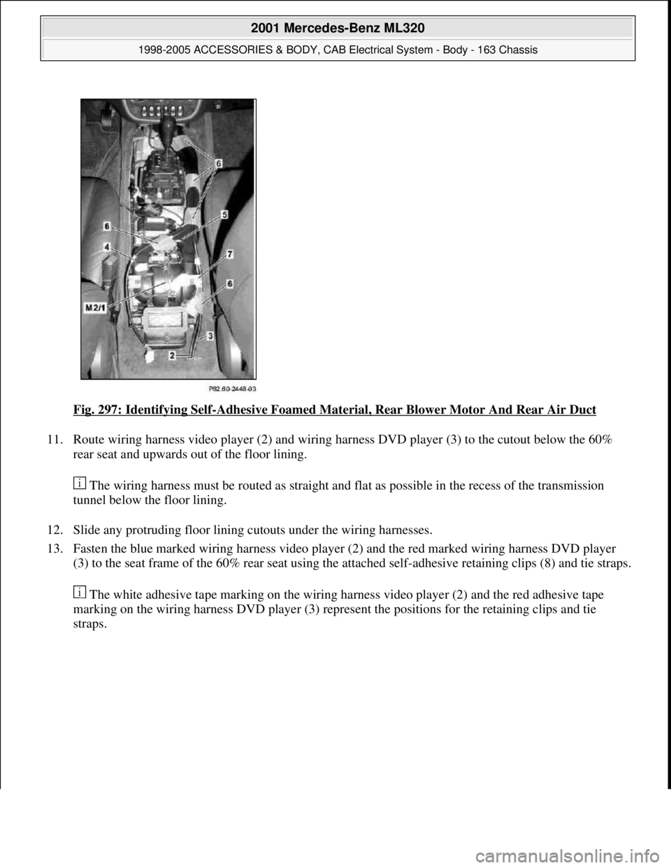
9. Fasten wiring harness to top side of rear air duct (5) with attached, self-adhesive foamed material (6).
10. Fasten video player and DVD player wiring harness to outside of bracket on center console (7) using
attached self-adhesive foamed material (6).
2001 Mercedes-Benz ML320
1998-2005 ACCESSORIES & BODY, CAB Electrical System - Body - 163 Chassis
me
Saturday, October 02, 2010 3:30:12 PMPage 381 © 2006 Mitchell Repair Information Company, LLC.
Page 1877 of 4133

Fig. 297: Identifying Self-Adhesive Foamed Material, Rear Blower Motor And Rear Air Duct
11. Route wiring harness video player (2) and wiring harness DVD player (3) to the cutout below the 60%
rear seat and upwards out of the floor lining.
The wiring harness must be routed as straight and flat as possible in the recess of the transmission
tunnel below the floor lining.
12. Slide any protruding floor lining cutouts under the wiring harnesses.
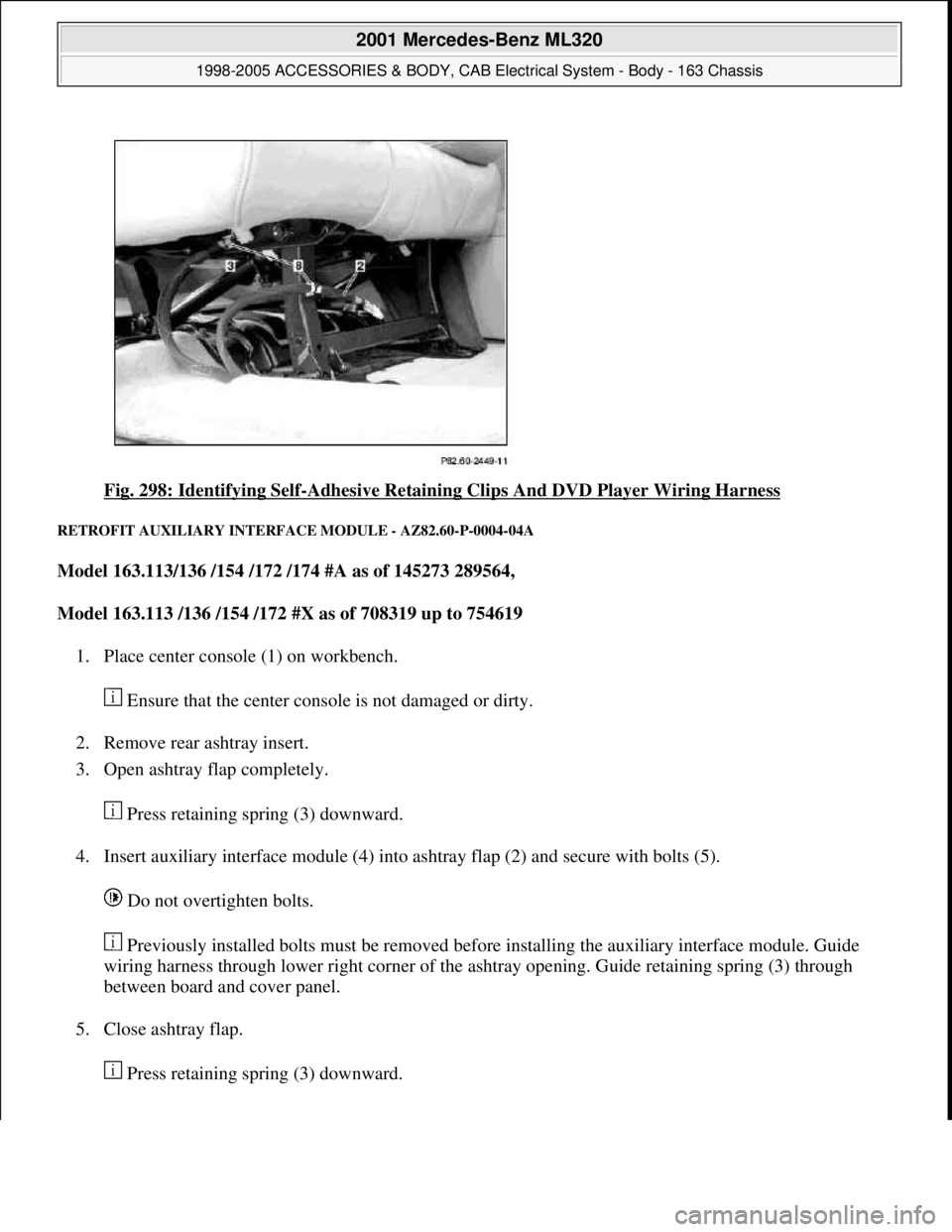
13. Fasten the blue marked wiring harness video player (2) and the red marked wiring harness DVD player
(3) to the seat frame of the 60% rear seat using the attached self-adhesive retaining clips (8) and tie straps.
The white adhesive tape marking on the wiring harness video player (2) and the red adhesive tape
marking on the wiring harness DVD player (3) represent the positions for the retaining clips and tie
straps.
2001 Mercedes-Benz ML320
1998-2005 ACCESSORIES & BODY, CAB Electrical System - Body - 163 Chassis
me
Saturday, October 02, 2010 3:30:12 PMPage 382 © 2006 Mitchell Repair Information Company, LLC.
Page 1878 of 4133

Fig. 298: Identifying Self-Adhesive Retaining Clips And DVD Player Wiring Harness
RETROFIT AUXILIARY INTERFACE MODULE - AZ82.60-P-0004-04A
Model 163.113/136 /154 /172 /174 #A as of 145273 289564,
Model 163.113 /136 /154 /172 #X as of 708319 up to 754619
1. Place center console (1) on workbench.
Ensure that the center console is not damaged or dirty.
2. Remove rear ashtray insert.
3. Open ashtray flap completely.
Press retaining spring (3) downward.
4. Insert auxiliary interface module (4) into ashtray flap (2) and secure with bolts (5).
Do not overtighten bolts.
Previously installed bolts must be removed before installing the auxiliary interface module. Guide
wiring harness through lower right corner of the ashtray opening. Guide retaining spring (3) through
between board and cover panel.
5. Close ashtray flap.
Press retainin
g spring (3) downward.
2001 Mercedes-Benz ML320
1998-2005 ACCESSORIES & BODY, CAB Electrical System - Body - 163 Chassis
me
Saturday, October 02, 2010 3:30:12 PMPage 383 © 2006 Mitchell Repair Information Company, LLC.
Page 1882 of 4133

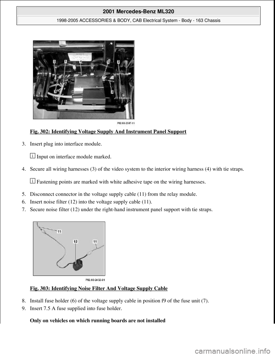
Fig. 302: Identifying Voltage Supply And Instrument Panel Support
3. Insert plug into interface module.
Input on interface module marked.
4. Secure all wiring harnesses (3) of the video system to the interior wiring harness (4) with tie straps.
Fastening points are marked with white adhesive tape on the wiring harnesses.
5. Disconnect connector in the voltage supply cable (11) from the relay module.
6. Insert noise filter (12) into the voltage supply cable (11).
7. Secure noise filter (12) under the right-hand instrument panel support with tie straps.
Fig. 303: Identifying Noise Filter And Voltage Supply Cable
8. Install fuse holder (6) of the voltage supply cable in position f9 of the fuse unit (7).
9. Insert 7.5 A fuse supplied into fuse holder.
Only on vehicles on which running boards are not installed
2001 Mercedes-Benz ML320
1998-2005 ACCESSORIES & BODY, CAB Electrical System - Body - 163 Chassis
me
Saturday, October 02, 2010 3:30:12 PMPage 387 © 2006 Mitchell Repair Information Company, LLC.
Page 1883 of 4133

10.
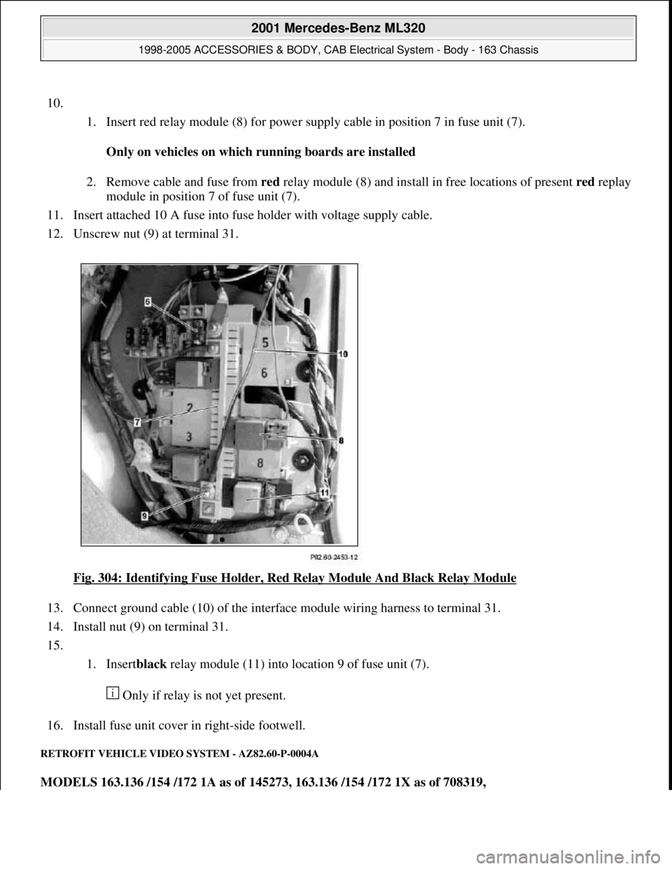
1. Insert red relay module (8) for power supply cable in position 7 in fuse unit (7).
Only on vehicles on which running boards are installed
2. Remove cable and fuse from red relay module (8) and install in free locations of present redreplay
module in position 7 of fuse unit (7).
11. Insert attached 10 A fuse into fuse holder with voltage supply cable.
12. Unscrew nut (9) at terminal 31.
Fig. 304: Identifying Fuse Holder, Red Relay Module And Black Relay Module
13. Connect ground cable (10) of the interface module wiring harness to terminal 31.
14. Install nut (9) on terminal 31.
15.
1. Insertblack relay module (11) into location 9 of fuse unit (7).
Only if relay is not yet present.
16. Install fuse unit cover in right-side footwell.
RETROFIT VEHICLE VIDEO SYSTEM - AZ82.60-P-0004A
MODELS 163.136 /154 /172 1A as of 145273, 163.136 /154 /172 1X as of 708319,
2001 Mercedes-Benz ML320
1998-2005 ACCESSORIES & BODY, CAB Electrical System - Body - 163 Chassis
me
Saturday, October 02, 2010 3:30:12 PMPage 388 © 2006 Mitchell Repair Information Company, LLC.
Page 1885 of 4133
Fig. 307: Identifying Wiring Harness Fo r Auxiliary Interface Module And Clip
Fig. 308: Identifying Auxiliary Interface Module Connector And Mount For Center Console
Remove
1Remove center console
Remove/install center
console AR68.20-P-2000GH
2Remove center console
insulating mat
3Remove rear air duct Up to VIN A289564,
X754619. 2 screws at
rear air duct.
4Remove radio (A2)
Remove/install radio AR82.60-P-7502EA
5Remove glove
compartment
2001 Mercedes-Benz ML320
1998-2005 ACCESSORIES & BODY, CAB Electr ical System - Body - 163 Chassis
me
Saturday, October 02, 2010 3:30:12 PMPage 390 © 2006 Mitchell Repair Information Company, LLC.