Page 2343 of 4133
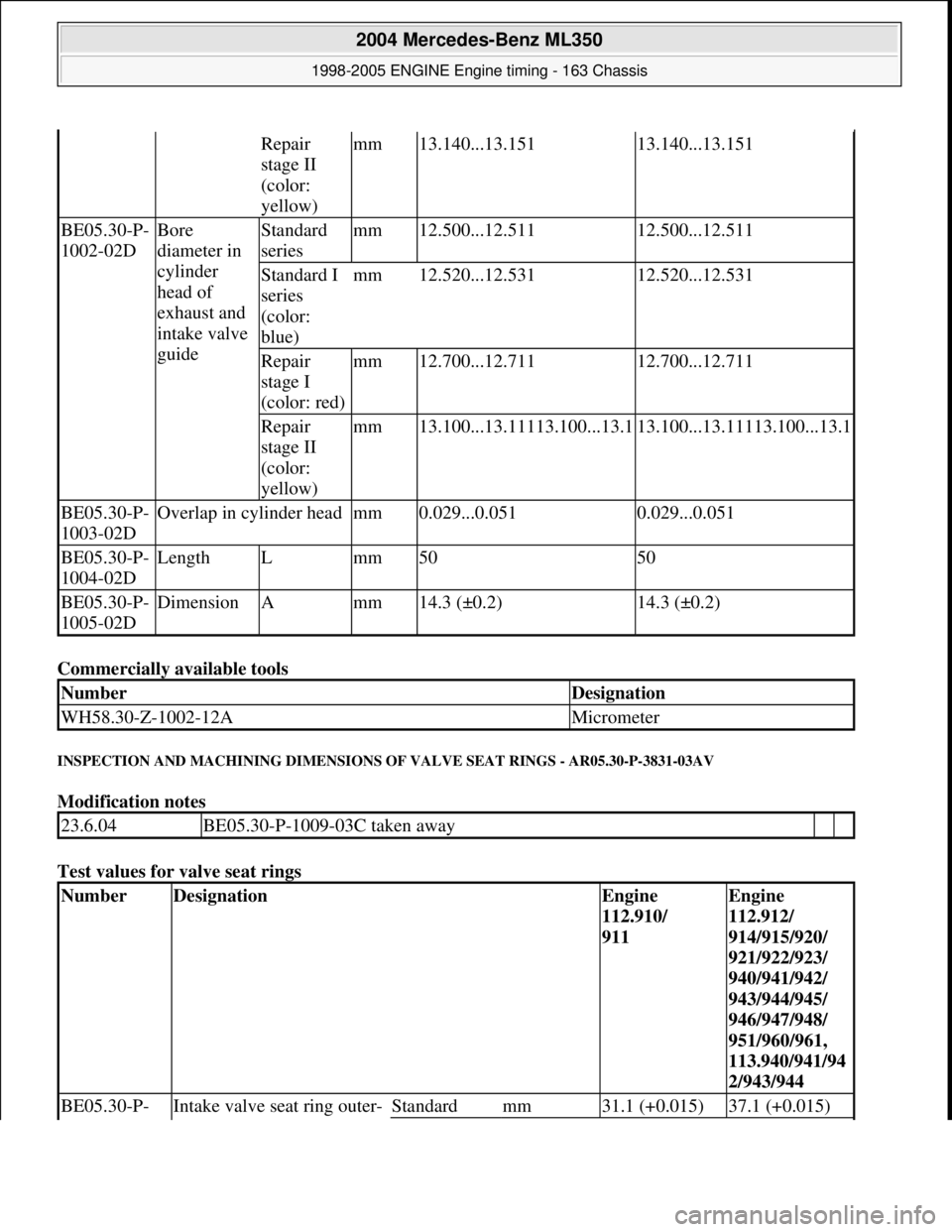
Commercially available tools
INSPECTION AND MACHINING DIMENSIONS OF VALVE SEAT RINGS - AR05.30-P-3831-03AV
Modification notes
Test values for valve seat rings
Repair
stage II
(color:
yellow)mm13.140...13.15113.140...13.151
BE05.30-P-
1002-02DBore
diameter in
cylinder
head of
exhaust and
intake valve
guideStandard
seriesmm12.500...12.51112.500...12.511
Standard I
series
(color:
blue)mm12.520...12.53112.520...12.531
Repair
stage I
(color: red)mm12.700...12.71112.700...12.711
Repair
stage II
(color:
yellow)mm13.100...13.11113.100...13.113.100...13.11113.100...13.1
BE05.30-P-
1003-02DOverlap in cylinder headmm0.029...0.0510.029...0.051
BE05.30-P-
1004-02DLengthLmm5050
BE05.30-P-
1005-02DDimensionAmm14.3 (±0.2)14.3 (±0.2)
NumberDesignation
WH58.30-Z-1002-12AMicrometer
23.6.04BE05.30-P-1009-03C taken away
NumberDesignationEngine
112.910/
911Engine
112.912/
914/915/920/
921/922/923/
940/941/942/
943/944/945/
946/947/948/
951/960/961,
113.940/941/94
2/943/944
BE05.30-P- Intake valve seat ring outer- Standardmm31.1 (+0.015)37.1 (+0.015)
2004 Mercedes-Benz ML350
1998-2005 ENGINE Engine timing - 163 Chassis
me
Saturday, October 02, 2010 3:39:39 PMPage 102 © 2006 Mitchell Repair Information Company, LLC.
Page 2351 of 4133
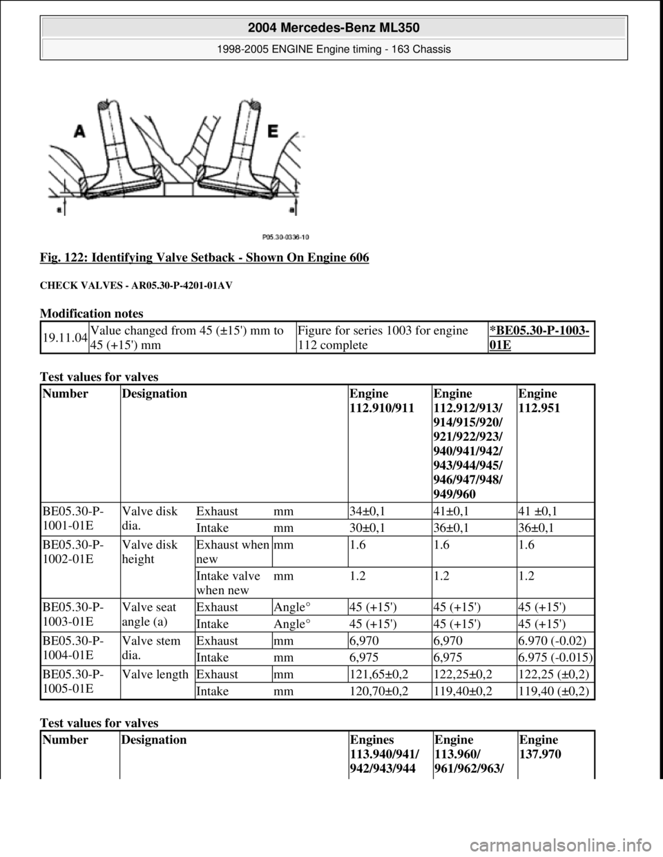
Fig. 122: Identifying Valve Setback - Shown On Engine 606
CHECK VALVES - AR05.30-P-4201-01AV
Modification notes
Test values for valves
Test values for valves
19.11.04Value changed from 45 (±15') mm to
45 (+15') mmFigure for series 1003 for engine
112 complete*BE05.30-P-1003-
01E
NumberDesignationEngine
112.910/911Engine
112.912/913/
914/915/920/
921/922/923/
940/941/942/
943/944/945/
946/947/948/
949/960Engine
112.951
BE05.30-P-
1001-01EValve disk
dia.Exhaustmm34±0,141±0,141 ±0,1
Intakemm30±0,136±0,136±0,1
BE05.30-P-
1002-01EValve disk
heightExhaust when
newmm1.61.61.6
Intake valve
when newmm1.21.21.2
BE05.30-P-
1003-01EValve seat
angle (a)ExhaustAngle°45 (+15')45 (+15')45 (+15')
IntakeAngle°45 (+15')45 (+15')45 (+15')
BE05.30-P-
1004-01EValve stem
dia.Exhaustmm6,9706,9706.970 (-0.02)
Intakemm6,9756,9756.975 (-0.015)
BE05.30-P-
1005-01EValve lengthExhaustmm121,65±0,2122,25±0,2122,25 (±0,2)
Intakemm120,70±0,2119,40±0,2119,40 (±0,2)
NumberDesignationEngines
113.940/941/
942/943/944Engine
113.960/
961/962/963/ Engine
137.970
2004 Mercedes-Benz ML350
1998-2005 ENGINE Engine timing - 163 Chassis
me
Saturday, October 02, 2010 3:39:39 PMPage 110 © 2006 Mitchell Repair Information Company, LLC.
Page 2352 of 4133
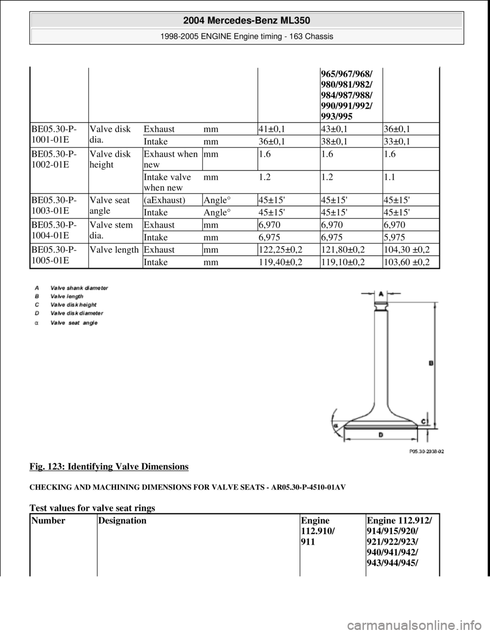
Fig. 123: Identifying Valve Dimensions
CHECKING AND MACHINING DIMENSIONS FOR VALVE SEATS - AR05.30-P-4510-01AV
Test values for valve seat rings
965/967/968/
980/981/982/
984/987/988/
990/991/992/
993/995
BE05.30-P-
1001-01EValve disk
dia.Exhaustmm41±0,143±0,136±0,1
Intakemm36±0,138±0,133±0,1
BE05.30-P-
1002-01EValve disk
heightExhaust when
newmm1.61.61.6
Intake valve
when newmm1.21.21.1
BE05.30-P-
1003-01EValve seat
angle(aExhaust)Angle°45±15'45±15'45±15'
IntakeAngle°45±15'45±15'45±15'
BE05.30-P-
1004-01EValve stem
dia.Exhaustmm6,9706,9706,970
Intakemm6,9756,9755,975
BE05.30-P-
1005-01EValve lengthExhaustmm122,25±0,2121,80±0,2104,30 ±0,2
Intakemm119,40±0,2119,10±0,2103,60 ±0,2
NumberDesignationEngine
112.910/
911Engine 112.912/
914/915/920/
921/922/923/
940/941/942/
943/944/945/
2004 Mercedes-Benz ML350
1998-2005 ENGINE Engine timing - 163 Chassis
me
Saturday, October 02, 2010 3:39:39 PMPage 111 © 2006 Mitchell Repair Information Company, LLC.
Page 2361 of 4133
Continuous individual traces of scratch
Caused by dirt, for example, through back pul sation of soot particles from the exhaust.
The crankcase can be reused.
Piston seizure
Most of cylinder wall perceptibly roughened over the entire length.
Material deposits and perceptible scoring ma rks on cylinder wall and at piston skirt.
The cylinder barrel is unusable.
Brown coloring of cylinder upper surface.
A brown coloration over large areas of the cylinder barrel is oil varnish and indicates that the engine has been
driven at a high temperature level.
The crankcase can be reused if no im permissible cylinder warping is visible
Oil varnish above piston ring zone is nor mal and is not a reason for complaint.
GENERAL NOTES: PASSENGER CARS: COMPLETE ENGINE, CRANKCASE VENTILATION, CYLINDER HEAD,
CRANKCASE - AH01.00-Z-9999AZ
MODEL all
Notes on application of
sealant to front cover of
cylinder head
ENGINE 629AH01.30-P-
1000-02TJ
Notes on sealant path for
oil panENGINE 642.970 in MODEL 463.303 /340 /341AH01.45-P-
0001-01GY
Notes on application of
sealant to oil panENGINE 629AH01.45-P-
0001-01TJ
General information on
inspecting cylinder wallsENGINE 272, 273AH01.00-P-
0300-01VA
Notes on the application of
sealant to the cylinder head
cover
ENGINE 122.9 in MODEL 454.0AH01.30-P-
1000-08FB
Notes on application of
sealant to oil panENGINE 113, 156...AH01.45-P-
0001-01GZ
Notes on the application of
sealing compound to the
cylinder head cover
ENGINE 273AH01.30-P-
1000-08SX
AH01.45-P-
2001 Mercedes-Benz ML320
1998-2005 ENGINE Complete engine - 163 Chassis
me
Saturday, October 02, 2010 3:17:55 PMPage 5 © 2006 Mitchell Repair Information Company, LLC.
Page 2427 of 4133
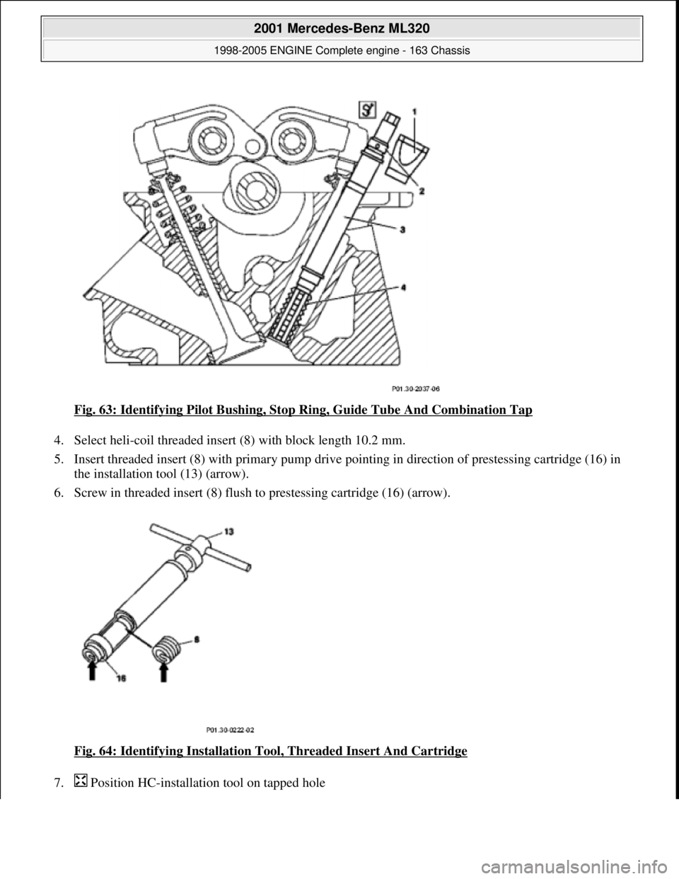
Fig. 63: Identifying Pilot Bushing, Stop Ring, Guide Tube And Combination Tap
4. Select heli-coil threaded inse rt (8) with block length 10.2 mm.
5. Insert threaded insert (8) with primary pump drive pointing in direction of prestessing cartridge (16) in
the installation tool (13) (arrow).
6. Screw in threaded insert (8) flush to prestessing cartridge (16) (arrow).
Fig. 64: Identifying Installation T ool, Threaded Insert And Cartridge
7. Position HC-installat ion tool on tapped hole
2001 Mercedes-Benz ML320
1998-2005 ENGINE Complete engine - 163 Chassis
me
Saturday, October 02, 2010 3:17:56 PMPage 71 © 2006 Mitchell Repair Information Company, LLC.
Page 2433 of 4133
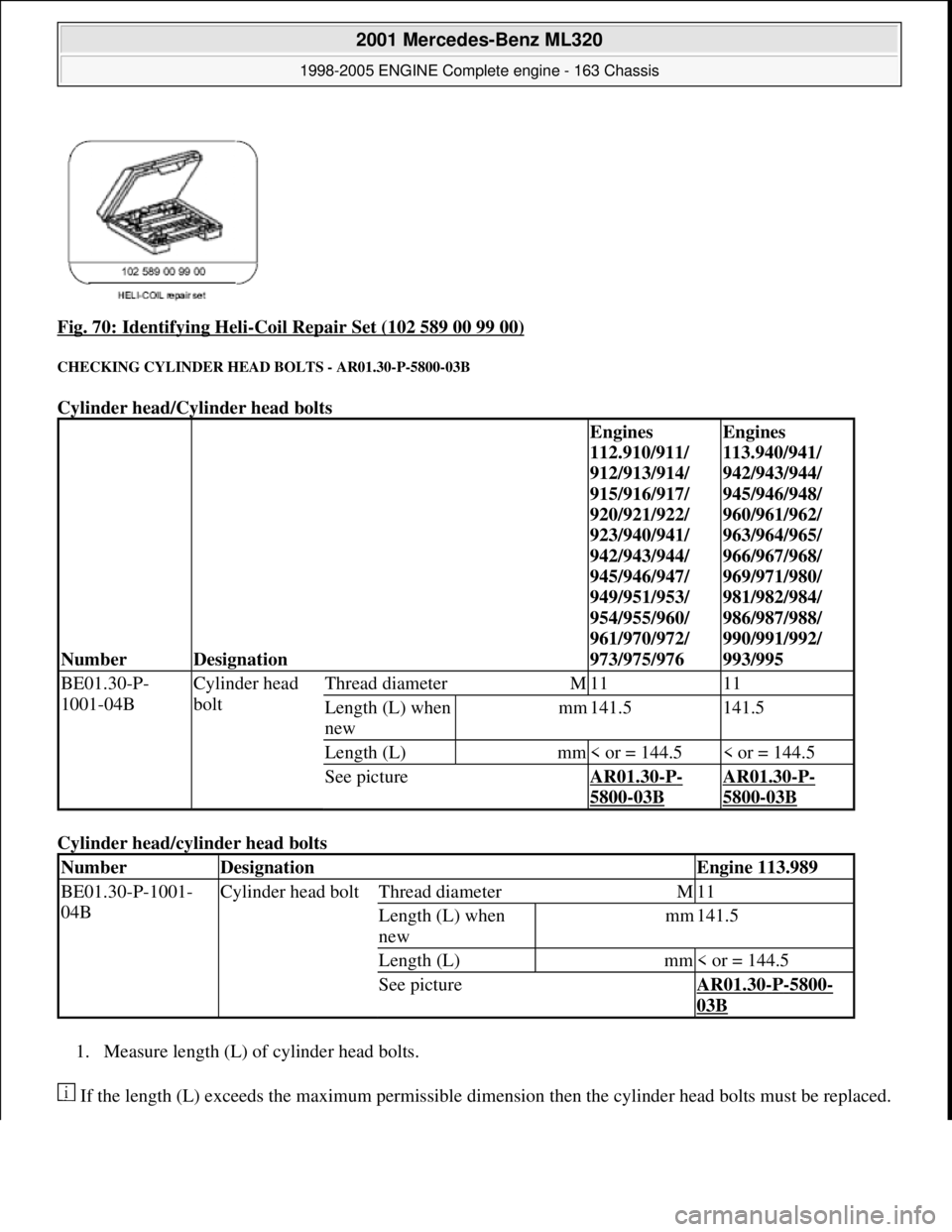
Fig. 70: Identifying Heli-Coil Repair Set (102 589 00 99 00)
CHECKING CYLINDER HEAD BOLTS - AR01.30-P-5800-03B
Cylinder head/Cylinder head bolts
Cylinder head/cyl inder head bolts
1. Measure length (L) of cylinder head bolts.
If the length (L) exceeds the maximu m permissible dimension then the cyli nder head bolts must be replaced.
NumberDesignation
Engines
112.910/911/
912/913/914/
915/916/917/
920/921/922/
923/940/941/
942/943/944/
945/946/947/
949/951/953/
954/955/960/
961/970/972/
973/975/976Engines
113.940/941/
942/943/944/
945/946/948/
960/961/962/
963/964/965/
966/967/968/
969/971/980/
981/982/984/
986/987/988/
990/991/992/
993/995
BE01.30-P-
1001-04BCylinder head
boltThread diameterM1111
Length (L) when
newmm141.5141.5
Length (L)mm< or = 144.5< or = 144.5
See pictureAR01.30-P-
5800-03B
AR01.30-P-
5800-03B
NumberDesignationEngine 113.989
BE01.30-P-1001-
04BCylinder head boltThread diameterM11
Length (L) when
newmm141.5
Length (L)mm< or = 144.5
See pictureAR01.30-P-5800-
03B
2001 Mercedes-Benz ML320
1998-2005 ENGINE Complete engine - 163 Chassis
me
Saturday, October 02, 2010 3:17:56 PMPage 77 © 2006 Mitchell Repair Information Company, LLC.
Page 2434 of 4133
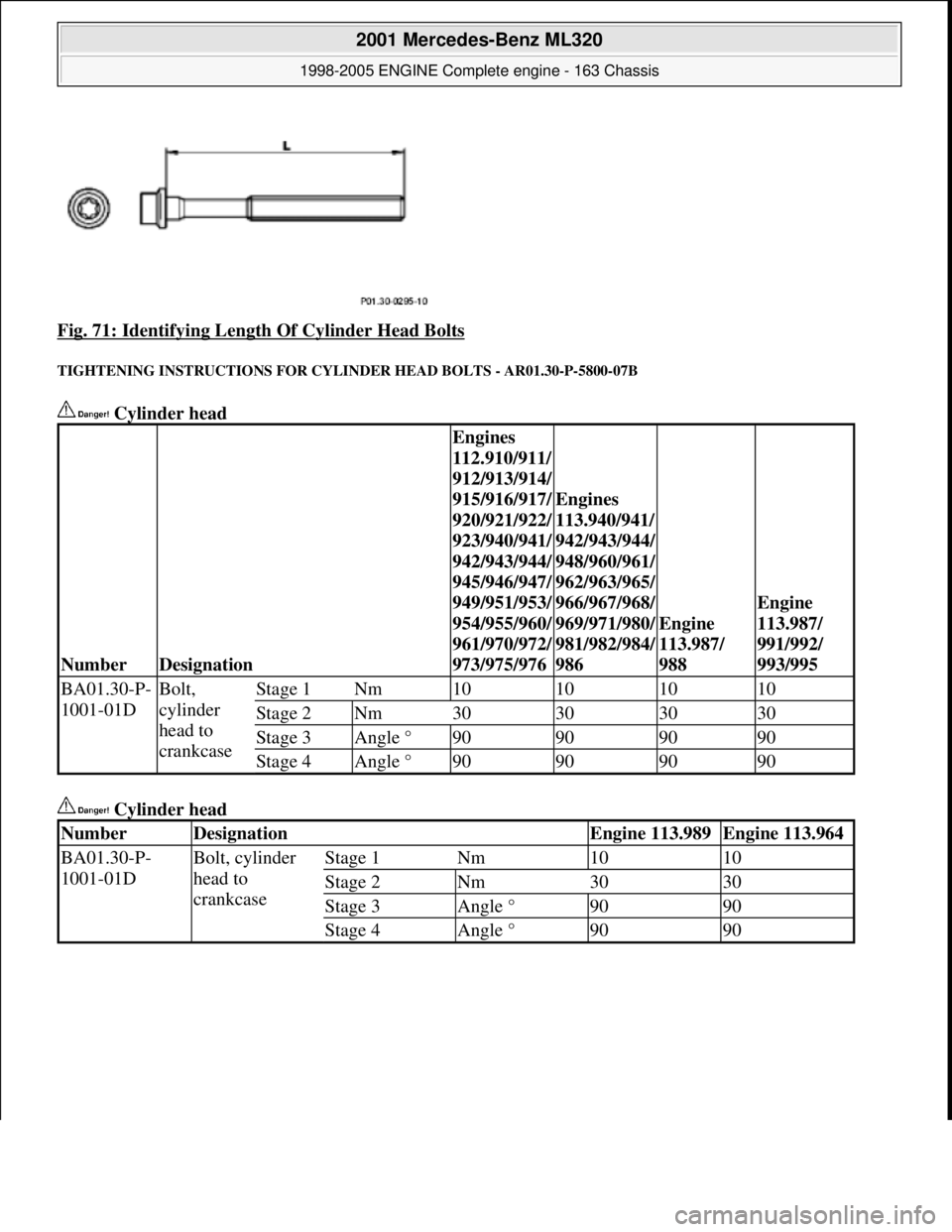
Fig. 71: Identifying Length Of Cylinder Head Bolts
TIGHTENING INSTRUCTIO NS FOR CYLINDER HEAD BOLTS - AR01.30-P-5800-07B
Cylinder head
Cylinder head
NumberDesignation
Engines
112.910/911/
912/913/914/
915/916/917/
920/921/922/
923/940/941/
942/943/944/
945/946/947/
949/951/953/
954/955/960/
961/970/972/
973/975/976
Engines
113.940/941/
942/943/944/
948/960/961/
962/963/965/
966/967/968/
969/971/980/
981/982/984/
986
Engine
113.987/
988
Engine
113.987/
991/992/
993/995
BA01.30-P-
1001-01DBolt,
cylinder
head to
crankcaseStage 1Nm10101010
Stage 2Nm30303030
Stage 3Angle °90909090
Stage 4Angle °90909090
NumberDesignationEngine 113.989Engine 113.964
BA01.30-P-
1001-01DBolt, cylinder
head to
crankcaseStage 1Nm1010
Stage 2Nm3030
Stage 3Angle °9090
Stage 4Angle °9090
2001 Mercedes-Benz ML320
1998-2005 ENGINE Complete engine - 163 Chassis
me
Saturday, October 02, 2010 3:17:56 PMPage 78 © 2006 Mitchell Repair Information Company, LLC.
Page 2436 of 4133
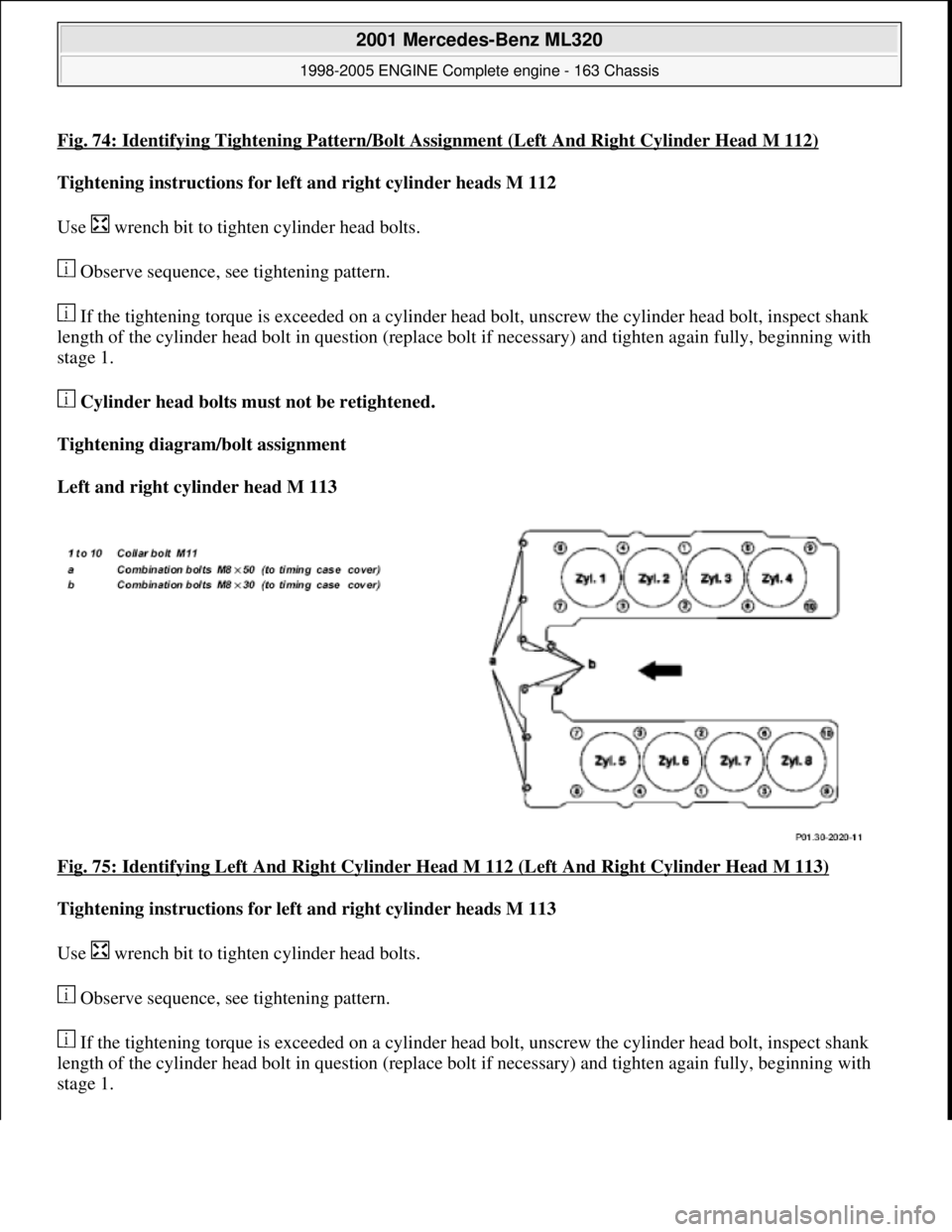
Fig. 74: Identifying Tightening Pattern/Bolt Assignment (Left And Right Cylinder Head M 112)
Tightening instructions for left and right cylinder heads M 112
Use wrench bit to tight en cylinder head bolts.
Observe sequence, see tightening pattern.
If the tightening torque is exceeded on a cylinder he ad bolt, unscrew the cylinder head bolt, inspect shank
length of the cylinder head bolt in question (replace bolt if necessary) and tighten again fully, beginning with
stage 1.
Cylinder head bolts must not be retightened.
Tightening diagram/bolt assignment
Left and right cylinder head M 113
Fig. 75: Identifying Left And Right Cylinder Head M 112 (Left And Right Cylinder Head M 113)
Tightening instructions for left and right cylinder heads M 113
Use wrench bit to tight en cylinder head bolts.
Observe sequence, see tightening pattern.
If the tightening torque is exceeded on a cylinder he ad bolt, unscrew the cylinder head bolt, inspect shank
length of the cylinder head bolt in question (replace bolt if necessary) and tighten again fully, beginning with
stage 1.
2001 Mercedes-Benz ML320
1998-2005 ENGINE Complete engine - 163 Chassis
me
Saturday, October 02, 2010 3:17:56 PMPage 80 © 2006 Mitchell Repair Information Company, LLC.