1997 MERCEDES-BENZ ML350 length
[x] Cancel search: lengthPage 2910 of 4133
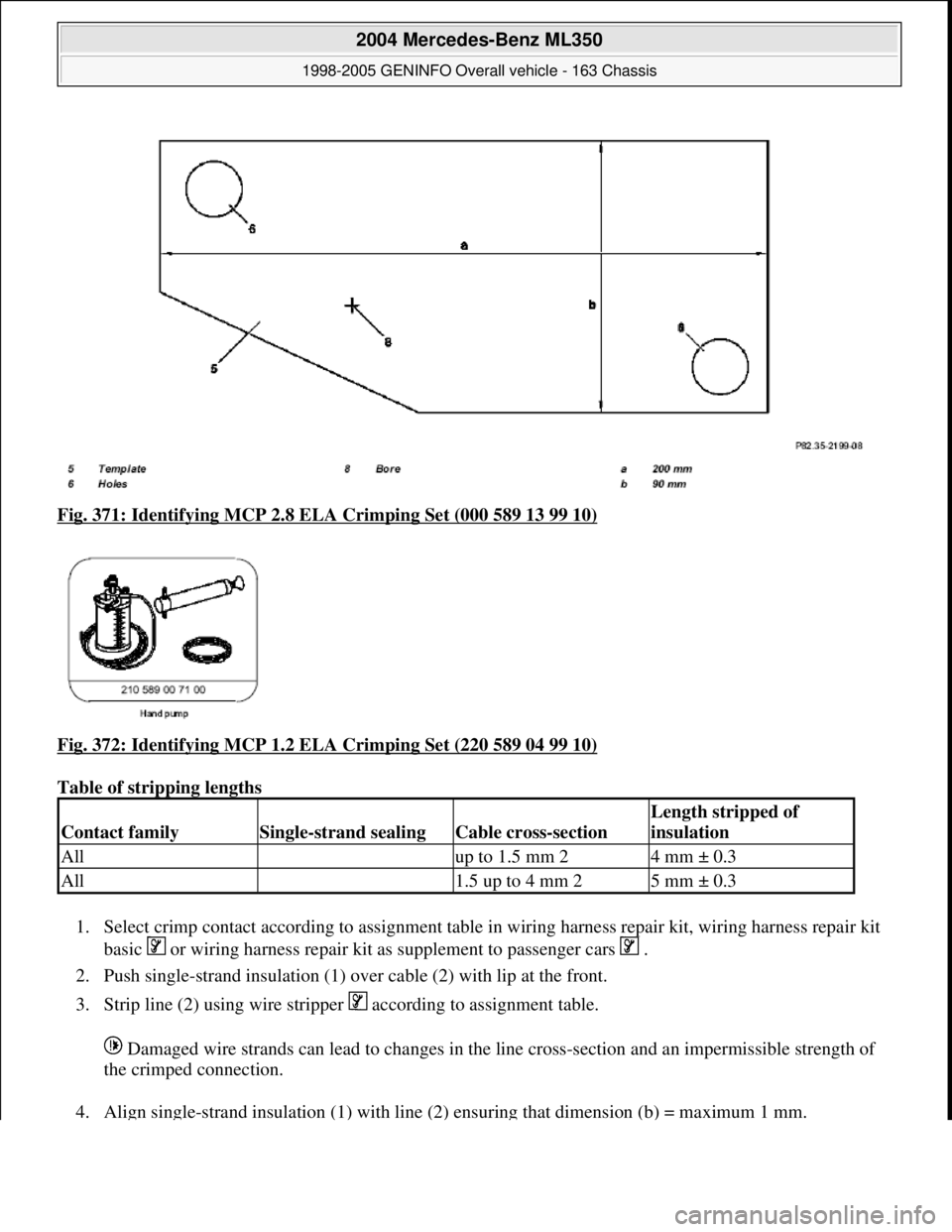
Fig. 371: Identifying MCP 2.8 EL A Crimping Set (000 589 13 99 10)
Fig. 372: Identifying MCP 1.2 EL A Crimping Set (220 589 04 99 10)
Table of stripping lengths
1. Select crimp contact accor ding to assignment table in wiring harnes s repair kit, wiring harness repair kit
basic or wiring harness repair kit as supplement to passenger cars .
2. Push single-strand insulation (1) over cable (2) with lip at the front.
3. Strip line (2) using wire strippe r according to assignment table.
Damaged wire strands can lead to changes in the line cross-section and an impermissible strength of
the crimped connection.
4. Ali
gn single-strand insulation (1) with line (2) ensuring that dimension (b) = maximum 1 mm.
Contact familySingle-strand sealingCable cross-section
Length stripped of
insulation
All up to 1.5 mm 24 mm ± 0.3
All 1.5 up to 4 mm 25 mm ± 0.3
2004 Mercedes-Benz ML350
1998-2005 GENINFO Overall vehicle - 163 Chassis
me
Saturday, October 02, 2010 3:47:48 PMPage 265 © 2006 Mitchell Repair Information Company, LLC.
Page 2915 of 4133
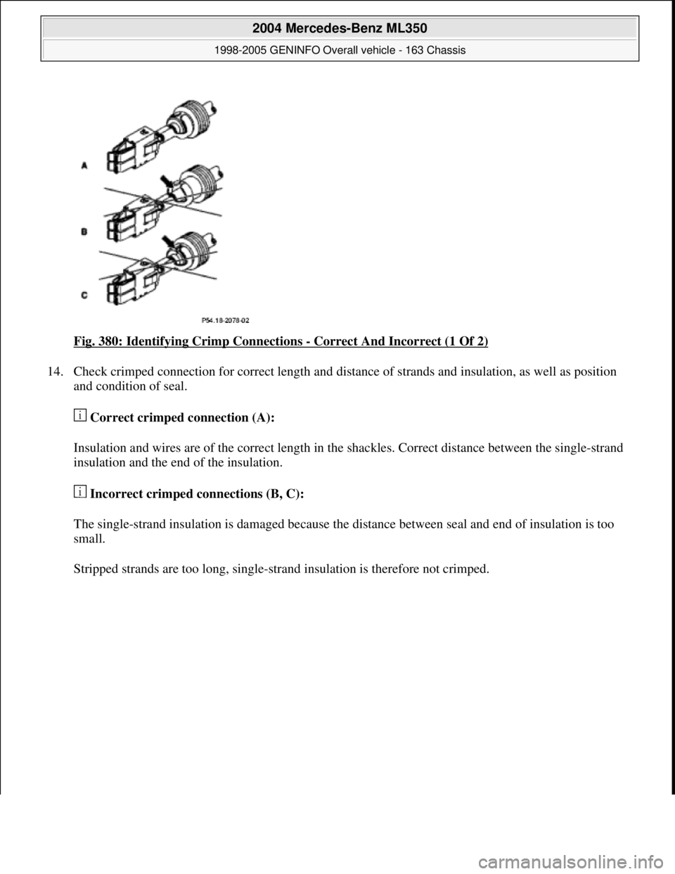
Fig. 380: Identifying Crimp Connections - Correct And Incorrect (1 Of 2)
14. Check crimped connection for correct length and distance of strands and insulation, as well as position
and condition of seal.
Correct crimped connection (A):
Insulation and wires are of the correct length in the shackles. Correct distance between the single-strand
insulation and the end of the insulation.
Incorrect crimped connections (B, C):
The single-strand insulation is damaged because the distance between seal and end of insulation is too
small.
Stripped strands are too lon
g, single-strand insulation is therefore not crimped.
2004 Mercedes-Benz ML350
1998-2005 GENINFO Overall vehicle - 163 Chassis
me
Saturday, October 02, 2010 3:47:49 PMPage 270 © 2006 Mitchell Repair Information Company, LLC.
Page 2924 of 4133
A maximum of seven individual cables maybe inserted into each solder connection.
5. Insert the cables into the corresponding solder connections (Z) according to the total cable cross-section.
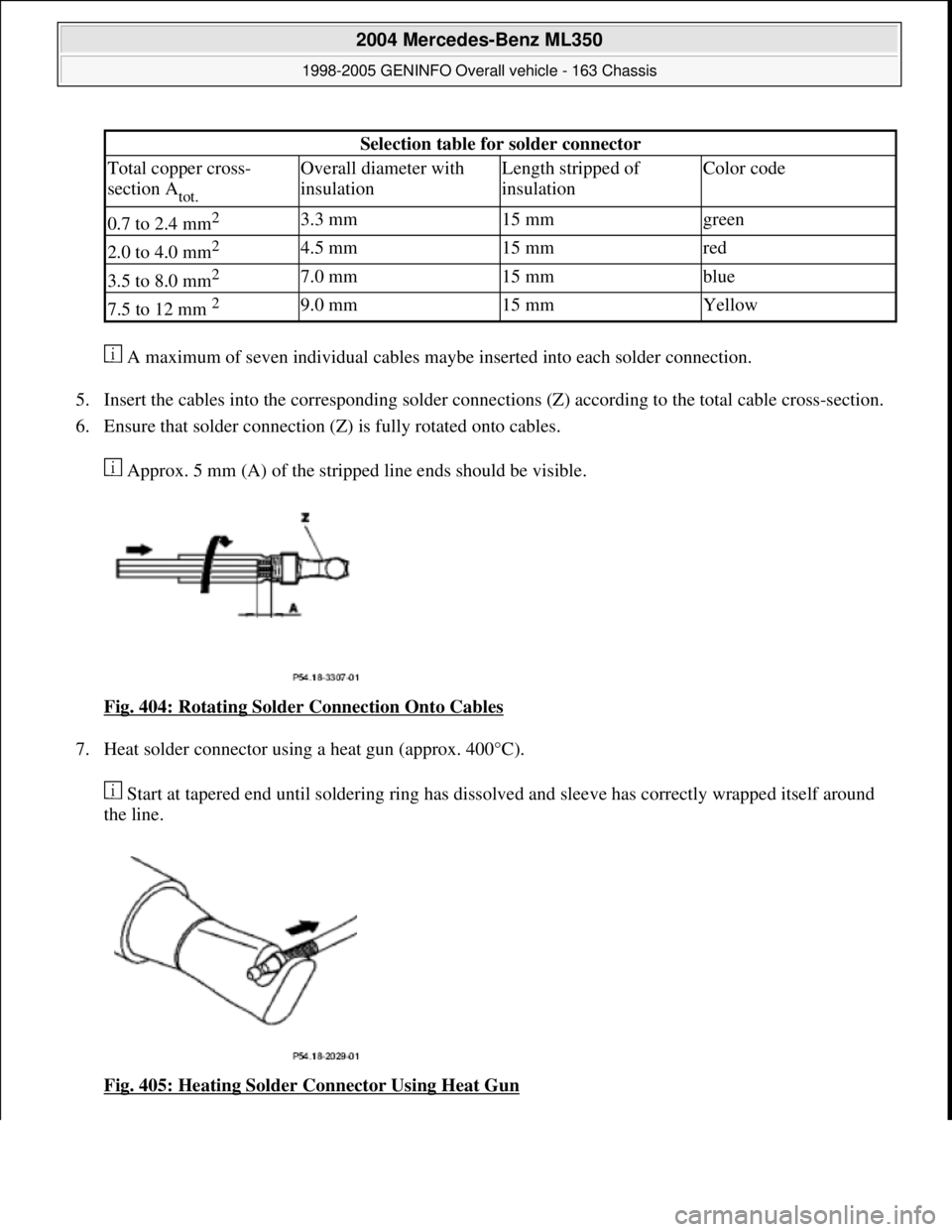
6. Ensure that solder connection (Z) is fully rotated onto cables.
Approx. 5 mm (A) of the stripped line ends should be visible.
Fig. 404: Rotating Solder Connection Onto Cables
7. Heat solder connector using a heat gun (approx. 400°C).
Start at tapered end until soldering ring has dissolved and sleeve has correctly wrapped itself around
the line.
Fig. 405: Heating Solder Connector Using Heat Gun
Selection table for solder connector
Total copper cross-
section A
tot.
Overall diameter with
insulationLength stripped of
insulationColor code
0.7 to 2.4 mm2 3.3 mm15 mmgreen
2.0 to 4.0 mm2 4.5 mm15 mmred
3.5 to 8.0 mm2 7.0 mm15 mmblue
7.5 to 12 mm 2 9.0 mm15 mmYellow
2004 Mercedes-Benz ML350
1998-2005 GENINFO Overall vehicle - 163 Chassis
me
Saturday, October 02, 2010 3:47:49 PMPage 279 © 2006 Mitchell Repair Information Company, LLC.
Page 3484 of 4133

AH40.10-P-9411-01A
Information on tires/rims
Model 124, 129, 140, 163, 168, 169,
170, 171, 199, 201, 202, 203, 208, 209,
210, 211, 215, 219, 220, 230, 240, 414,
450, 452,
639
Tires
D
For service conversions, the tire/disc wheel specifications and
dimensions should be compared with the entries in the
registration papers.
D
When mounting tires, the tires and rims must be carefully
matched in order to guarantee the concentricity of the wheel.
Identification of matching points on:
- Tires with a colored dot on the outside of the tire,
- Sheet steel disk wheel by a colored dot or punch mark on the
outside of the wheel,
- Perform this operation at the valve stem hole on light-alloy
disk wheels
With an additional paint spot or punch mark in the rim base
for the 140 Model Series.
D
Always replace the rubber valve.
-----------------------------------------------------------------------------------------
D
Damaged and defective tires must always be replaced. The
repair methods employed in the tire trade are not approved by
Mercedes-Benz. Small nicks (<0.8mm) on the tire's sidewall do
not usually pose a cause for concern, and continued use of
such tires is approved
D When replacing just one tire, install it on the front of the vehicle.
This does not apply to vehicles with different tires of varying
specifications on the front and rear wheels.
D
Only use tires listed in the valid Service Information bulletins
and repair instructions.
D
If the permissible maximum speed of an M+S tire is below the
maximum speed of the vehicle, an appropriate adhesive plate
must be attached in the driver's field of view.
-----------------------------------------------------------------------------------------
D
Tires permissible for higher speeds may be used.
D
Always fit all rims with tires of the same design, make and
version.
-----------------------------------------------------------------------------------------
D
Run in new tires for approx. 100 km at moderate speed.
D
Handed tires must be installed according to the arrow on the
side wall of the tire.
D
Tires are subject to an aging process with negative effects on
the properties of the tire. In order to ensure optimum
effectiveness in winter, M+S tires should not be used for longer
than 3 years.
-----------------------------------------------------------------------------------------
Tire pressure
(For specified values see tire pressure table in the fuel filler flap, on
the Vaneo BM 414 see B-pillar on the passenger side).
Too low tire pressure increases the rolling resistance and increases
the flexing energy of the tire. This causes the critical temperature limit
to be exceeded (carcass detachment) and destroys the tire. Respond
to loss of tire pressure by determining the source and replacing the
tire as indicated.
Cleaning
Using a spray wand with high-pressure nozzles to clean the wheel
can lead to tire damage. Such damage occurs especially on the tire
side walls. The following should be observed when using flat jet
nozzles:
D
Maintain a minimum distance of 300 mm
D
Do not direct the water jet at a single point on the surface of the
tire for any length of time.
-----------------------------------------------------------------------------------------
Mounting in bearings
Before putting into storage, clean tires thoroughly and check for
damage and adequate tread depth. Mark the position and running
direction of the tires with chalk. Do not store tires outdoors. Under the
influence of sunlight, heat, moving air and ozone the rubber looses
elasticity and strength, ages more quickly and becomes cracked.
Storage areas should be dry, cool and dark. Avoid drafts by keeping
doors and windows closed as much as possible. Do not bring tires
into contact with gasoline, oil or other greases as they dissolve the
rubber.
Disposal
Collection, storage and disposal should be performed in accordance
with the legal requirements and the company's own regulations.
-----------------------------------------------------------------------------------------
Copyright DaimlerChrysler AG 06.07.2006 CD-Ausgabe G/10/04 . This WIS print-out will not be recorde
d by Modification services.
Page 1
Page 3746 of 4133

11
Oil piston pin (2) and conrod bush
12
Assemble piston (3) and conrod (4)
Install piston (3) with arrow in direction of
travel.
13
Push in piston pin (2) by hand
14
Insert circlip (1) of piston pin (2) in the groove
on piston (3)
Do not damage piston (3). Place a clean
cloth underneath.
15
Oil cleaned parts (cylinder bore, conrod
bearing journal, conrod bearing shells and
pistons)
16
Fit on tensioning strap (10) and tension
Piston ring gaps must be offset 120°.
Tensioning strap
*000589041400
17
Install piston (3) with arrow pointing in
direction of travel
Rotate crankshaft far enough so that the
connecting rod when inserting piston into
cylinder bore does not line up at the
connecting rod journal!
18
Inspect conrod bolts (6)
AR03.10-P-6111-01BV
Thread and shank length
*BE03.10-P-1001-03A
19
Install conrod bearings and fit on conrod
bearing cap (5)
The connecting rod bearing shell (7) with
oil drilling (arrow) must be mounted in the
connecting rod, otherwise the piston pin (2) is
not lubricated.
The anti-twist locks (8) of the connecting rod
bearing shells (7) must be seated in the
grooves (9) in the conrods (4) and connecting
rod bearing caps (5).
AR03.10-P-6111-06AV
The connecting rod and connecting rod
bearing cap are cracked (broken) (arrow).
They must not be installed the wrong side
round!
20
Tighten conrod bolts (6)
AR03.10-P-6111-02BV
*BA03.10-P-1001-01E
21
Rotate crankshaft
To inspect ease of operation.
22
Install oil pump
-
Ensure oil return flow check valve is
correctly located.
-
Clean strainer of oil pump.
-
Fill oil pump with engine oil before
installing so that it pumps oil when first
started.
All except models 203, 209, 211.061/065/070,
220 without 4MATIC, 230.474 /475
AR18.10-P-6020B
Model 203 without 4MATIC, 209,
211.061/065/070
AR18.10-P-6020PV
Model 203 with 4MATIC, model 220 with
4MATIC
AR18.10-P-6020PW
Model 230.474/475
AR18.10-P-6020R
23
Fit on cylinder head
Models 463.206/ 209/ 232/ 233/ 240/ 241/
243/ 244/ 245/ 246/ 247/ 248/ 249/ 250/ 254
AR01.30-P-5800GV
Engine 112 in model 129 and engine 113 in
models 129, 202, 208, 210
AR01.30-P-5800B
Engine 112 in models 170, 202, 208, 210,
220 and engine 113 in models 220,
230.474 /475
AR01.30-P-5800BA
Model 163
AR01.30-P-5800MV
Models 203, 209 with engines 112, 113
Models 211.061/065/070
AR01.30-P-5800PV
24
Fit on top part of oil pan
Model 463
AR01.45-P-7500FG
Model 230.474/475
AR01.45-P-7500R
Model 220 without 4MATIC
AR01.45-P-7500I
Model 220 with 4MATIC
AR01.45-P-7500IW
Model 210 with 4MATIC
AR01.45-P-7500FA
Model 210 without 4MATIC
AR01.45-P-7500F
Models 202, 208
AR01.45-P-7500FC
Model 203 without 4MATIC, 209 with engines
112,113
AR01.45-P-7500PV
Model 203 with 4MATIC
AR01.45-P-7500PW
Model 211.061/065/070
AR01.45-P-7500TV
Model 170
AR01.45-P-7500SV
Model 163
AR01.45-P-7500FB
Model 129
AR01.45-P-7500FD
Copyright DaimlerChrysler AG 20.05.2006 CD-Ausgabe G/10/04 . This WIS print-out will not be recorde
d by Modification services.
Page 3
Page 3747 of 4133

25.1
Fit on automatic transmission
Models 463.206/ 209/ 232/ 233/ 240/ 241
AR27.10-P-0500BD
Models 463.243/ 244/ 245/ 246/ 247/ 248/
249/ 250/ 254
AR27.10-P-0500GA
Model 230.475
AR27.10-P-0500R
Model 230.474
Model 220 without 4MATIC
AR27.10-P-0500I
Model 220 with 4MATIC
AR27.10-P-0500IW
Models 210, 208, 202,170. 129
AR27.10-P-0500B
Model 203 without 4MATIC, 209 with engines
112,113
AR27.10-P-0500P
Model 203 with 4MATIC
AR27.10-P-0500PW
Models 211.061/065/070
AR27.10-P-0500T
Model 163
AR27.10-P-0500GH
25.2
Fit on manual transmission
Models 210, 202, 129
AR26.10-P-0020A
Models 203, 209 with engine 112
AR26.10-P-0020P
Model 211.061
AR26.10-P-0020T
Model 208 with transmissions 716.662/622
AR26.10-P-0020E
Model 170,
Model 208 with transmission 716.663
AR26.10-P-0020D
26
Install engine
Models 463.243/ 244/ 245/ 246/ 247/ 248/
249/ 250/ 254
AR01.10-P-2400CC
Model 230.475
AR01.10-P-2400R
Model 230.474
AR01.10-P-2400RVK
Model 220 without 4MATIC
AR01.10-P-2400AB
Model 220 with 4MATIC
AR01.10-P-2400IW
Model 210 with 4MATIC
AR01.10-P-2400C
Model 210 without 4MATIC, 208, 202, 129
AR01.10-P-2400CB
Model 203 without 4MATIC, 209 with engine
112
AR01.10-P-2400PV
Model 203 with 4MATIC
AR01.10-P-2400PW
Model 209 with engine 113
AR01.10-P-2400Q
Models 211.061/065/070
AR01.10-P-2400TC
Model 170
AR01.10-P-2400SV
Model 163
AR01.10-P-2400CA
Inspection data of conrod bolts
Number
Designation
Engine
112 except
112.951,
113.94/96/980/
981/982/984/986
Engine
113.992
BE03.10-P-1001-03A
Conrod bolts
Thread
4M8B18B1
Shank length
when new
mm
4742
max.
mm
47.642.6
Part no.
--
Designation
Engines
112 except
112.951,
113.940/941/
942/943/944/
945/946/948/
960/961/962/
963/965/966/
967/968/980/
981/982/984/
986/987/988/
990/991/992/
993
BA03.10-P-1001-01E
Connecting rod bolt
Stage 1
Nm
5
2nd stage
Nm
25
Copyright DaimlerChrysler AG 20.05.2006 CD-Ausgabe G/10/04 . This WIS print-out will not be recorde
d by Modification services.
Page 4
Page 3751 of 4133

GF54.30-P-3017A
Quartz, location/task/function
8.7.99
MODEL
129, 140 as of 1.6.96,
163, 168, 170,
202 as of 1.8.96,
208,
210 as of 1.6.96,
215, 220
P54.30-0519-01
Piezo-electric effect:
A thin quartz plate (c) is coated on two opposing sides with a conductive material (a), (b) (see
illustration). If a tensile or compressive load is applied to the array, an electrical voltage "U" i
s
produced between the points (d) and (e). The polarity of the generated voltage depends on the
direction of load (compression/tension).
Reversed piezo-electric effect:
If, however, a voltage is applied to the points (d) and (e), the quartz plate increases or decreases
in length.
Task:
Mechanical vibrations can be converted into electrical oscillations using the piezo-electric effect.
For example, for microphones, knock sensors, pressure sensors.
Electrical oscillations can be converted into mechanical vibrations or motion using the reversed
piezo-electric effect: piezo-electric speakers, actuators.
Both effects are combined in the quartz resonator: If an AC voltage whose frequency is roughly
equal to the mechanical resonant frequency (fundamental or harmonic component) of the quartz
plate is applied to the points (d) and (e), the quartz is stimulated to generate resonant vibrations
which stabilize the frequency of the electrical oscillations. For this reason, quartz resonators are
often used where a high degree of frequency stability is required (e.g. in clock generators
(oscillators) for electronic clocks and microprocessors).
Copyright DaimlerChrysler AG 05.06.2006 CD-Ausgabe G/10/04 . This WIS print-out will not be recorde
d by Modification services.
Page 1
Page 3928 of 4133
Test values for shock absorber
the projection length (a) of
the piston rod.
Push in piston rod as
far as it will go. Then hold
vertically so that piston
rod points down, and
measure projection length
(a) of piston rod.
Shock absorber in new
condition:
Shock absorber in used
condition:
Model 129, 170, 202, 208,
210, 211, 230*BE32.25-P-1002-02A
Model 129, 170, 202, 208,
210, 211, 230
If shock absorber exceeds
specified value, dispose of
it:
By workshop: ?*BE32.25-P-1001-02A
Disposing of shock
absorberModel 129, 170, 202, 208,
210OS32.25-P-0121-01A
Model 211OS32.25-P-0121-01TX
Model 230
Disposal by scrap
dealer: ?
Notes on scrapping gas-
filled hydraulic
componentsOS00.00-P-1000-01A
4.1Check rubber mount in
housing eye, replace if
necessary Only on shock
absorbers with rubber
mount in housing eye and
only if the shock absorber
is not replaced.
The rubber mounts
must be seated securely in
the body eye and must not
be cracked or damaged.
If fitted, damaged rubber
mounts can cause
knocking noises.
NumberDesignationModel 129Model 170Model 202
BE32.25-P-1001- Oil reserve check mm0+20+20+2
2001 Mercedes-Benz ML320
1998-2005 SUSPENSION Suspension - 163 Chassis
me
Saturday, October 02, 2010 3:37:36 PMPage 20 © 2006 Mitchell Repair Information Company, LLC.