1997 MERCEDES-BENZ ML350 oil filter
[x] Cancel search: oil filterPage 3236 of 4133
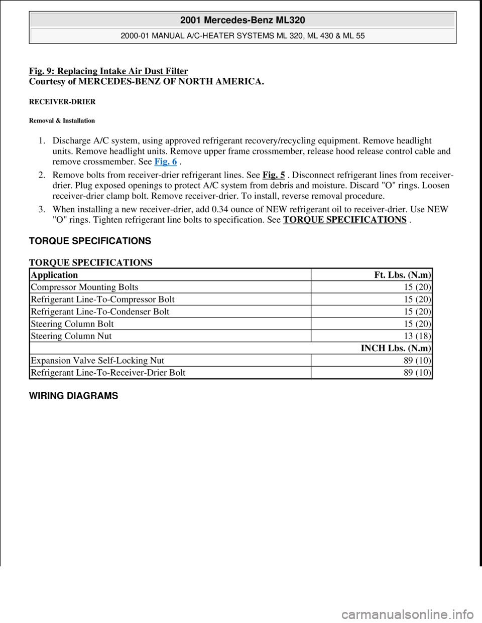
Fig. 9: Replacing Intake Air Dust Filter
Courtesy of MERCEDES-BENZ OF NORTH AMERICA.
RECEIVER-DRIER
Removal & Installation
1. Discharge A/C system, using approved refrigerant recovery/recycling equipment. Remove headlight
units. Remove headlight units. Remove upper frame crossmember, release hood release control cable and
remove crossmember. See Fig. 6
.
2. Remove bolts from receiver-drier refrigerant lines. See Fig. 5
. Disconnect refrigerant lines from receiver-
drier. Plug exposed openings to protect A/C system from debris and moisture. Discard "O" rings. Loosen
receiver-drier clamp bolt. Remove receiver-drier. To install, reverse removal procedure.
3. When installing a new receiver-drier, add 0.34 ounce of NEW refrigerant oil to receiver-drier. Use NEW
"O" rings. Tighten refrigerant line bolts to specification. See TORQUE SPECIFICATIONS
.
TORQUE SPECIFICATIONS
TORQUE SPECIFICATIONS
WIRING DIAGRAMS
ApplicationFt. Lbs. (N.m)
Compressor Mounting Bolts15 (20)
Refrigerant Line-To-Compressor Bolt15 (20)
Refrigerant Line-To-Condenser Bolt15 (20)
Steering Column Bolt15 (20)
Steering Column Nut13 (18)
INCH Lbs. (N.m)
Expansion Valve Self-Locking Nut89 (10)
Refrigerant Line-To-Receiver-Drier Bolt89 (10)
2001 Mercedes-Benz ML320
2000-01 MANUAL A/C-HEATER SYSTEMS ML 320, ML 430 & ML 55
me
Saturday, October 02, 2010 3:25:10 PMPage 25 © 2006 Mitchell Repair Information Company, LLC.
Page 3444 of 4133
CORRECTING OIL LEVEL IN AIR CONDITIONING FOLLOWING REPAIR OR SLOW REFRIGERANT LOSS - AR83.30-P-
5251E
MODEL 163 with CODE (580) Air conditioning or Tempmatic for USA
A/C compressor 7SB16
MODEL 202 with CODE (580) Air conditioning or Tempmatic for USA with CODE (581a) Air
conditioning (Automatic) A/C compressor ND6CA17, A/C compressor 7SB16
MODEL 208 with CODE (580) Air conditioning or Tempmatic for USA with CODE (581a) Air
conditioning (Automatic) A/C compressor 7SB16
MODEL 210 with CODE (580) Air conditioning or Tempmatic for USA with CODE (581a) Air
conditioning (Automatic) A/C compressor 7SB16
MODELS 215,220 A/C compressor 7SE16
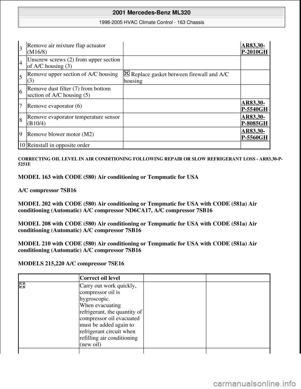
3Remove air mixture flap actuator
(M16/8) AR83.30-
P-2010GH
4Unscrew screws (2) from upper section
of A/C housing (3)
5Remove upper section of A/C housing
(3) Replace gasket between firewall and A/C
housing
6Remove dust filter (7) from bottom
section of A/C housing (5)
7Remove evaporator (6) AR83.30-
P-5540GH
8Remove evaporator temperature sensor
(B10/4) AR83.30-
P-8085GH
9Remove blower motor (M2) AR83.30-
P-5560GH
10Reinstall in opposite order
Correct oil level
Carry out work quickly,
compressor oil is
hygroscopic.
When evacuating
refrigerant, the quantity of
compressor oil evacuated
must be added again to
refrigerant circuit when
refilling air conditioning
(new oil)
2001 Mercedes-Benz ML320
1998-2005 HVAC Climate Control - 163 Chassis
me
Saturday, October 02, 2010 3:23:18 PMPage 200 © 2006 Mitchell Repair Information Company, LLC.
Page 3474 of 4133
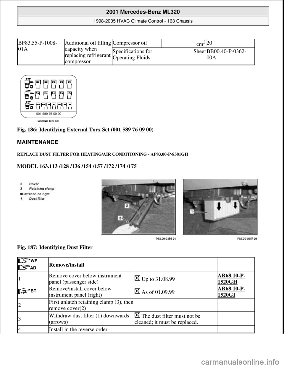
Fig. 186: Identifying External Torx Set (001 589 76 09 00)
MAINTENANCE
REPLACE DUST FILTER FOR HEATIN G/AIR CONDITIONING - AP83.00-P-8381GH
MODEL 163.113 /128 /136 /154 /157 /172 /174 /175
Fig. 187: Identifying Dust Filter
BF83.55-P-1008-
01AAdditional oil filling
capacity when
replacing refrigerant
compressorCompressor oilcm3 20
Specifications for
Operating FluidsSheetBB00.40-P-0362-
00A
Remove/install
1Remove cover below instrument
panel (passenger side) Up to 31.08.99AR68.10-P-
1520GH
Remove/install cover below
instrument panel (right) As of 01.09.99AR68.10-P-
1520GI
2First unlatch retaining clamp (3), then
remove cover(2)
3Withdraw dust filter (1) downwards
(arrows) The dust filter must not be
cleaned; it must be replaced.
4Install in the reverse order
2001 Mercedes-Benz ML320
1998-2005 HVAC Climate Control - 163 Chassis
me
Saturday, October 02, 2010 3:23:19 PMPage 230 © 2006 Mitchell Repair Information Company, LLC.
Page 3718 of 4133
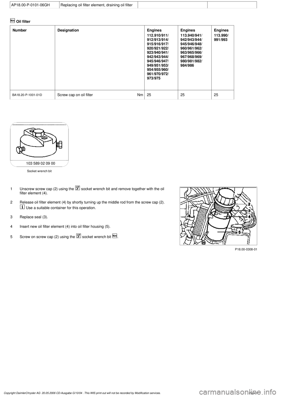
AP18.00-P-0101-06GH
Replacing oil filter element, draining oil filter
Oil filter
Number
Designation
Engines
112.910/911/
912/913/914/
915/916/917/
920/921/922/
923/940/941/
942/943/944/
945/946/947/
949/951/953/
954/955/960/
961/970/972/
973/975
Engines
113.940/941/
942/943/944/
945/946/948/
960/961/962/
963/965/966/
967/968/969/
980/981/982/
984/986
Engines
113.990/
991/993
BA18.20-P-1001-01D
Screw cap on oil filter
Nm
252525
103 589 02 09 00
Socket wrench bit
1
Unscrew screw cap (2) using the
socket wrench bit and remove together with the oil
filter element (4).
2
Release oil filter element (4) by shortly turning up the middle rod from the screw cap (2).
Use a suitable container for this operation.
3
Replace seal (3).
4
Insert new oil filter element (4) into oil filter housing (5).
5
Screw on screw cap (2) using the
socket wrench bit
.
P18.00-0308-01
Copyright DaimlerChrysler AG 20.05.2006 CD-Ausgabe G/10/04 . This WIS print-out will not be recorde
d by Modification services.
Page 1
Page 3719 of 4133
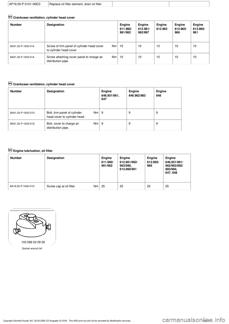
AP18.00-P-0101-06EG
Replace oil filter element, drain oil filter
Crankcase ventilation, cylinder head cover
Number
Designation
Engine
611.960/
961/962
Engine
612.961/
962/967
Engine
612.963
Engine
612.965/
966
Engine
613.960/
961
BA01.20-P-1002-01A
Screw of trim panel of cylinder head cover
to cylinder head cover
Nm
1010101010
BA01.20-P-1003-01A
Screw attaching cover panel to charge air
distribution pipe
Nm
1010101010
Crankcase ventilation, cylinder head cover
Number
Designation
Engine
646.951/961,
647
Engine
646.962/963
Engine
648
BA01.20-P-1002-01G
Bolt, trim panel of cylinder
head cover to cylinder head
Nm
999
BA01.20-P-1003-01G
Bolt, cover to charge air
distribution pipe.
Nm
999
Designation
Engine
611.960/
961/962
Engine
612.961/962/
963/990,
613.960/961
Engine
612.965/
966
Engine
646.951/961/
962/963/982/
983/984,
647, 648
BA18.20-P-1002-01G
Screw cap at oil filter
Nm
25252525
Socket wrench bit
103 589 02 09 00
Copyright DaimlerChrysler AG 20.05.2006 CD-Ausgabe G/10/04 . This WIS print-out will not be recorde
d by Modification services.
Page 1
Page 3720 of 4133
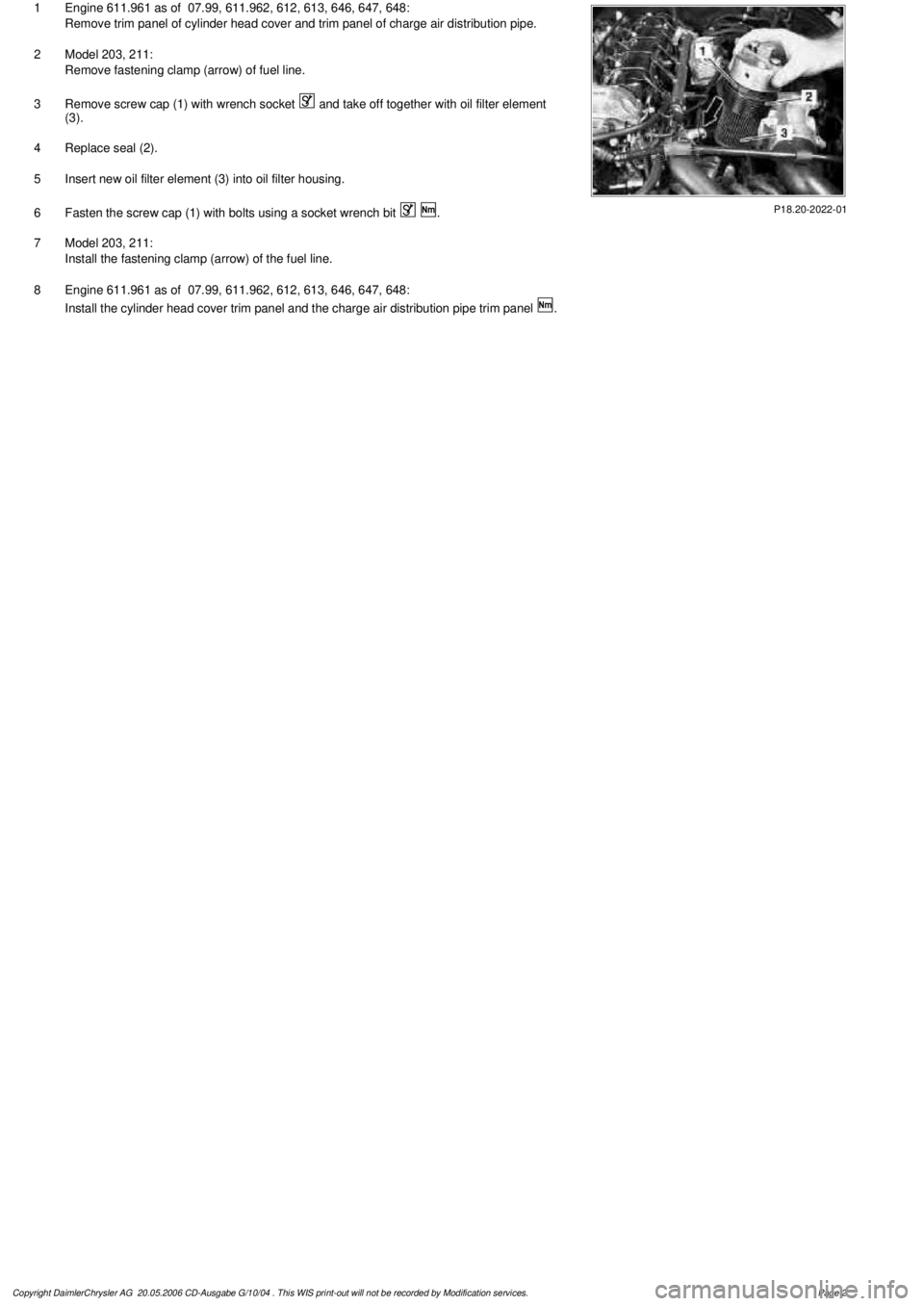
P18.20-2022-01
1
Engine 611.961 as of 07.99, 611.962, 612, 613, 646, 647, 648:
Remove trim panel of cylinder head cover and trim panel of charge air distribution pipe.
2
Model 203, 211:
Remove fastening clamp (arrow) of fuel line.
3
Remove screw cap (1) with wrench socket
and take off together with oil filter element
(3).
4
Replace seal (2).
5
Insert new oil filter element (3) into oil filter housing.
6
Fasten the screw cap (1) with bolts using a socket wrench bit
.
7
Model 203, 211:
Install the fastening clamp (arrow) of the fuel line.
8
Engine 611.961 as of 07.99, 611.962, 612, 613, 646, 647, 648:
Install the cylinder head cover trim panel and the charge air distribution pipe trim panel
.
Copyright DaimlerChrysler AG 20.05.2006 CD-Ausgabe G/10/04 . This WIS print-out will not be recorde
d by Modification services.
Page 2
Page 3775 of 4133
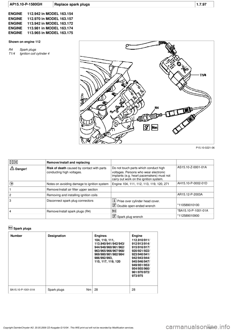
AP15.10-P-1580GHReplace spark plugs
1.7.97
ENGINE
112.942 in MODEL 163.154
ENGINE
112.970 in MODEL 163.157
ENGINE
113.942 in MODEL 163.172
ENGINE
113.981 in MODEL 163.174
ENGINE
113.965 in MODEL 163.175
P15.10-0221-06
Shown on engine 112
R4
Spark plugs
T1/4
Ignition coil cylinder 4
Remove/install and replacing
Danger!
Risk of death
caused by contact with parts
conducting high voltages.
Do not touch parts which conduct high
voltages. Persons who wear electronic
implants (e.g. heart pacemakers) must not
carry out work on the ignition system.
AS15.10-Z-0001-01A
Notes on avoiding damage to ignition system
Engine 104, 111, 112, 113, 119, 120, 271
AH15.10-P-0002-01D
1
Remove/install air filter upper section
2
Removing and installing ignition coils
AR15.12-P-2003A
3
Disconnect spark plug connectors
Prise over cylinder head cover.
Double open-ended wrench
*110589010100
4
Remove/install spark plugs (R4)
*BA15.10-P-1001-01A
Spark plug wrench
*112589010900
Spark plugs
Number
Designation
Engines
104, 110, 111,
113.940/941/942/943/
944/948/960/961/962/
963/965/966/967/968/
969/980/981/982/984/
986/992/993,
115, 117, 119, 120
Engine
112.910/911/
912/913/914/
915/916/917/
920/921/922/
923/940/941/
942/943/944/
945/946/947/
949/951/953/
954/955/960/
961/970/972/
973/975
BA15.10-P-1001-01A
Spark plugs
Nm
2828
Copyright DaimlerChrysler AG 20.05.2006 CD-Ausgabe G/10/04 . This WIS print-out will not be recorde
d by Modification services.
Page 1
Page 3835 of 4133

SI18.00-P-0010A
Service Information: oil sludge
26.3.01
ENGINE
111 in MODELS 124, 163, 170, 202, 203, 208, 210
ENGINE
112 in MODELS 129, 163, 170, 202, 203, 208, 210, 220
ENGINE
112, 113 in MODEL 463
ENGINE
113 in MODELS 129, 163, 202, 208, 210, 215, 220
ENGINE
137 in MODEL 215, 220
ENGINE
166 in MODEL 168
Oil sludging in gasoline engines with ASSYST maintenance
system
Recently we have determined that time and time again oil
sludging occurs in gasoline engines with an ASSYST maintenance
system.
Oil sludging can lead to the following complaints:
D
engine oil consumption
D
engine smoke (white/blue)
D
influencing of oil level indicator
D
clogged oil filter, engine oil thickened like jelly
D
Check engine lamp illuminated
D
oil sludge visible during assembly job, e.g. in oil filter, in cylinder
head covers, condensation sludging
(engine 166) etc.
-----------------------------------------------------------------------------------------
The following list of causes may lead individually or as a combination
to engine oil sludging:
D
Crankcase ventilation inoperable, function orifices, bores,
passages in cylinder head cover, cylinder head, crankcase etc.
are mechanically sealed. A nonfunctioning crankcase
ventilation boosts loads on the engine oil through organic
nitrates. The risk of oil sludging increases.
The mechanical condition of the engine is always to be
checked, i.e. all engine oil drain orifices on the cylinder head
and crankcase and all crankcase ventilation ducts must be free
of obstacles. Crankcase breather lines may not be kinked.
Check the ventilation bores in the cylinder head covers.
-----------------------------------------------------------------------------------------
D
The engine oil used does not comply with the specifications in
Sheet 229.1 or 229.3 of the Specifications for Service Products.
The additive process, e.g. dirt-carrying capability, neutralization
capability and oxidation resistance as well as the quality of the
base stock influence sludging time.
Use of engine oils with best possible resistance to formation of
sludge, i.e. use only tested and approved engine oils (from
Sheet 229.1 or 229.3). The best protection is afforded by the
engine oils on Sheet 229.3, which fulfill more stringent
specifications with regard to preventing sludge and deposits
(see Sheet 221.0, page 11). These oils have a distinctly better
anti-sludge characteristic than other engine oils.
D
Sludging after adding a fuel or engine oil special additive.
Do not use fuel or engine oil special additives. More information
hereto is available on Sheet 219.0 of the Specifications for
Service products. Reference to customer not to use special
additives.
D
Engine oil change not performed according to ASSYST
specifications. At driven distances
exceeding > approx. 3000 km, engine oil sludging may occur.
-----------------------------------------------------------------------------------------
Comply with engine oil and filter change as under ASSYST
specifications. Observe remaining distance.
D
Fuel grade lies outside standard (regionally contingent). If
contaminated, deficient fuel is used, then engine oil sludging
may occur even where approved engine oil is used.
Operation with fuel, e.g. as under DIN EN 228. Clarify refueling
behavior of customer. If engine operation regional, is
temporarily possible with deficient oil only, then the startup
distance has to be individually reduced, i.e. the oil change
temporarily performed at an interval of, e.g. 10,000 km.
D
Radiator antifreeze penetration into engine oil, e.g. through an
internal engine leak (cylinder head gasket, casting porosity).
The engine oil sludges within a short period. The crankcase
ventilation clogs up and stops functioning. Condensation
sludging clogs up the oil separator cells
(engine 166).
Rectify coolant leakage. Clean all sludged engine parts, in
particular the crankcase ventilation parts. If the occurrence
repeats, and casting porosity is suspected, e.g. replace
crankcase.
-----------------------------------------------------------------------------------------
Copyright DaimlerChrysler AG 20.05.2006 CD-Ausgabe G/10/04 . This WIS print-out will not be recorde
d by Modification services.
Page 1